Table of Contents
Advertisement
Quick Links
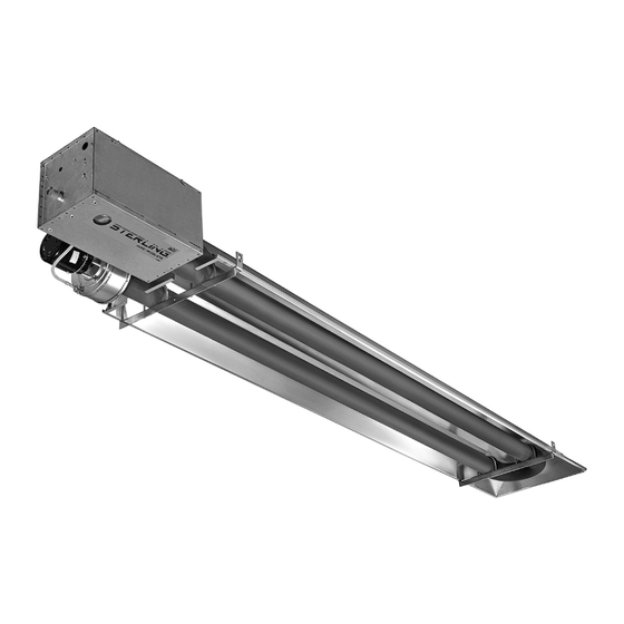
STERLING "RSG" SERIES
INFRARED RADIANT TUBE HEATER
RSG SERIES TUBE HEATERS
RSG 25
RSG 35
(Check One)
NATURAL GAS
(Check One)
EQUIPMENT USED:
ACCESSORIES:
Chain Mounting Kit:
Thermostat:
Gas Pressure Regulator:
Gas Shut-Off Valve:
3/17
RSG 45
PROPANE GAS
260 North Elm St., Westfield, MA 01085
(413) 564-5540
Vent Cap:
Combustion Air Cap:
Other:
Other:
PROJECT:
UNIT TAG:
Fax: (413) 562-5311
www.sterlinghvac.com
RSGS-2
Advertisement
Table of Contents

Related Manuals for Sterling RSG Series


Summary of Contents for Sterling RSG Series
- Page 1 STERLING “RSG” SERIES INFRARED RADIANT TUBE HEATER RSGS-2 RSG SERIES TUBE HEATERS RSG 25 RSG 35 RSG 45 (Check One) NATURAL GAS PROPANE GAS (Check One) EQUIPMENT USED: ACCESSORIES: Chain Mounting Kit: Vent Cap: Thermostat: Combustion Air Cap: Gas Pressure Regulator:...
-
Page 2: General Information
Although these heaters may be used in many Gas Code ANSI Z223.1/NFPA54 or the Natural Gas applications other than space heating (e.g., process heating), Sterling will not recognize the warranty for and Propane Installation Code CSA B149.1. Heaters shall be installed by a licensed contractor or licensed any use other than space heating. -
Page 3: Minimum Clearances To Combustibles
NFPA54 requires that the installer must post signs that will “specify the maximum permissible stacking height to maintain the required clearances from the heater to combustibles.” Sterling recommends posting these signs adjacent to the heater thermostat or other suitable location that will provide enhanced visibility. -
Page 4: Specifications
5/64” (0.078) * MOUNT HEATERS AS HIGH AS POSSIBLE. Minimums are shown as a guideline for human comfort and uniform energy distribution for complete building heating applications. Consult your Sterling representative for the particulars of your installation requirements. Type Gas-Pipe... - Page 5 STERLING “RSG” SERIES INFRARED RADIANT TUBE HEATER 4 ) DIMENSIONS...
-
Page 6: Accessory Packages
STERLING “RSG” SERIES INFRARED RADIANT TUBE HEATER 5 ) ACCESSORY PACKAGES A. Exhaust Hood Package, Part #42924000 Contains: Exhaust Hood Assembly, #42925540…....… QTY–1 #8-18 x 1/2 Self-Drilling Screws, #02189030…..… QTY–2 B. Deflector Kit, Part #43504010 The Deflector Kit is available for use to reduce the clearances to combustibles below the heater. -
Page 7: Gas Connections And Regulations
STERLING “RSG” SERIES INFRARED RADIANT TUBE HEATER 6 ) GAS CONNECTIONS AND REGULATIONS US ONLY: A gas connector certified for use on a CANADA ONLY: A Type I hose connector should tubular type infrared heater per the standard for be used that is certified as being in compliance Connectors for Gas Appliances, ANSI Z21.24/CSA... -
Page 8: Gas Pressure Table
STERLING “RSG” SERIES INFRARED RADIANT TUBE HEATER 7 ) GAS PRESSURE TABLE SUPPLY PRESSURE GAS TYPE MANIFOLD PRESSURE Minimum* Maximum Natural Gas 3.5" W.C. 5" W.C. 14" W.C. Propane Gas 10.0" W.C. 11" W.C. 14" W.C. *Minimum permissible gas supply pressure for purpose of input adjustment. -
Page 9: Electrical Connections
STERLING “RSG” SERIES INFRARED RADIANT TUBE HEATER 8 ) ELECTRICAL CONNECTIONS INTERNAL CONNECTION WIRING DIAGRAM — Direct Spark Ignition... - Page 10 STERLING “RSG” SERIES INFRARED RADIANT TUBE HEATER 9 ) THERMOSTAT CONNECTION WIRING DIAGRAMS A. LINE VOLTAGE (120V) THERMOSTAT CONNECTIONS – SINGLE HEATER PER THERMOSTAT B. LINE VOLTAGE (120V) THERMOSTAT CONNECTIONS – MULTIPLE HEATERS PER THERMOSTAT...
- Page 11 STERLING “RSG” SERIES INFRARED RADIANT TUBE HEATER C. LOW VOLTAGE (24V) THERMOSTAT CONNECTIONS – SINGLE HEATER PER THERMOSTAT Order 24V Relay Kit (Part No. 43274020) for Low Voltage (24V) thermostat connection. NOTES: a. If any of the original wire as supplied with the appliance must be replaced, it must be replaced with wiring material having a temperature rating of at least 105°C.
- Page 12 STERLING “RSG” SERIES INFRARED RADIANT TUBE HEATER 10 ) VENTING A. BASIC FLUE VENTING — Venting must comply with the latest edition of the National Fuel Gas Code (ANSI Z223.1-latest edition) or the authority having jurisdiction. Other venting references are in the equipment volume of the ASHRAE Handbook.
- Page 13 STERLING “RSG” SERIES INFRARED RADIANT TUBE HEATER 7. When the vent pipe passes through areas where unoccupied attic or concealed space and shall not the ambient temperature is likely to induce pass through any attic, inside wall or concealed condensation of the flue gases, the vent pipe space, or through any floor.
- Page 14 STERLING “RSG” SERIES INFRARED RADIANT TUBE HEATER SINGLE HEATER VENTING 3. Avoid locating elbows in the first 5 feet of vent (HORIZONTAL THROUGH SIDEWALL) pipe whenever possible. Limit the quantity of 90° This heater, when horizontally vented, must be installed elbows to two (2).
-
Page 15: Multiple Heater Venting (Connections Into A Common Vent Or Manifold)
STERLING “RSG” SERIES INFRARED RADIANT TUBE HEATER MULTIPLE HEATER VENTING (CONNECTIONS c) Where possible, use a Y-connector to the INTO A COMMON VENT OR MANIFOLD) common vent. Requirements for venting of multiple heaters are the same as described for “SINGLE HEATER VENTING”... - Page 16 STERLING “RSG” SERIES INFRARED RADIANT TUBE HEATER Multiple Heater Venting (Connections into a Manifold) B. INDIRECT VENTING (UNVENTED HEATERS) — VENT SIZING TABLE — Multiple Heater Venting COMMERCIAL AND INDUSTRIAL INSTALLATIONS Number of Heaters ONLY — This heater requires ventilation in the building...
-
Page 17: Direct Outside Air For Combustion
STERLING “RSG” SERIES INFRARED RADIANT TUBE HEATER 11 ) AIR FOR COMBUSTION If indoor combustion air is to be supplied for a tightly In contaminated atmospheres or high humidity areas, enclosed area, one square inch of free area opening optional outside air for combustion is recommended. - Page 18 STERLING “RSG” SERIES INFRARED RADIANT TUBE HEATER...
-
Page 19: Sequence Of Operation
STERLING “RSG” SERIES INFRARED RADIANT TUBE HEATER 13 ) SEQUENCE OF OPERATION The chart below shows the sequence of operation for the normal operating cycle. If the flame is not sensed during sequence T3 then the burner will automatically begin ignition sequence T2. - Page 20 Warranty INFRARED HEATER Sterling (“the Manufacturer”) warrants to the original owner at the original installation site that the Sterling Model Infrared Heater will be free from defects in material and workmanship for one (1) year from the date of shipment from the factory.
Need help?
Do you have a question about the RSG Series and is the answer not in the manual?
Questions and answers