Advertisement
Quick Links
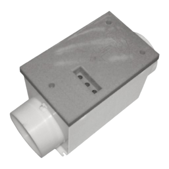
1.0 Introduction
This constant volume damper is designed for installation with
Nuaire's range of fans.
Units are rectangular in section, manufactured from galvanised
steel.
The CVD damper will control the flowrate passing through it when
the pressure drop across the damper is within the range stated in
the performance envelope.
Two flow settings are available; trickle and boost. The damper will
operate in the trickle setting when it is powered up and will go into
the boost setting when a mains signal is received at the SL terminal
or when the CVD-PIR (optional ancillary) is activated. A run-on timer
(adjustable between 1 to 60 minutes) will hold the damper in the
boost setting for the preset time period.
2.0 Dimensions
Plan view
Airflow
Side view
Dimensions in mm.
Code
A
B
CVD125
300
180
CVD150
300
200
CVD200
300
230
3.0 Handling
Handle the units carefully to avoid damage and distortion to
moving parts.
4.0 System Design
A nominal pressure drop must be allowed in order to ensure
adequate airflow through the damper. To ensure the airflow
pattern through the damper produces consistent readings; the
pressure drop across the damper should not exceed the
recommended value. Recommended values are listed in the table
following and show the performance envelope of each damper.
Nominal design pressure is the value needed to produce the
maximum rated airflow for the damper. If the desired flowrate
is less than the maximum, a lower design value may be used
by reading off the lower curve of the appropriate chart. Please
allow 40Pa (min).
Nuaire: A Trading Division of Polypipe Limited Western Industrial Estate Caerphilly United Kingdom CF83 1NA
T: 029 2088 5911 F: 029 2088 7033 E: info@nuaire.co.uk W: www.nuaire.co.uk
CVD125/150/200
Constant Volume Dampers
Installation and Maintenance
Figure 1.
A
F
C
D
E
F
kg
195
125
75
400
3.5
220
150
90
400
3.7
275
200
115
400
4
Model code
Nominal design
pressure drop
CVD125
70Pa
CVD150
80Pa
CVD200
90Pa**
*recommended maximum operating pressure to ensure the damper
would work within calibration limits.
Keep the duct velocity as low as possible to ensure the system
produces the lowest energy usage, preferably below 5m/s.
**Allow 90Pa for duties below 100l/s and 150Pa for duties between
100l/s and 125l/s.
Figure 2. Performance envelope for CVD125.
180
160
140
120
100
80
60
40
20
0
0
10
20
Figure 3. Performance envelope for CVD150.
250
200
150
100
design pressure
50
0
0
20
Figure 4. Performance envelope for CVD200.
300
250
200
150
Nominal design pressure
100
50
0
0
20
40
*Allow 90Pa for duties below 100l/s and 150Pa for duties between
100l/s and 125l/s.
1
The EMC Directive
2014/30/EU
The Low Voltage
Directive
2014/35/EU
Maximum pressure
across damper*
140Pa
160Pa
200Pa
design pressure
30
40
50
Volume flowrate l/s
40
60
80
Volume flowrate l/s
*
60
80
120
100
Volume flowrate l/s
10. 05. 17. Leaflet Number 671638
60
100
140
160
Advertisement

Related Manuals for NuAire CVD125


Summary of Contents for NuAire CVD125
- Page 1 Please 100l/s and 125l/s. allow 40Pa (min). Nuaire: A Trading Division of Polypipe Limited Western Industrial Estate Caerphilly United Kingdom CF83 1NA T: 029 2088 5911 F: 029 2088 7033 E: info@nuaire.co.uk W: www.nuaire.co.uk 10. 05. 17. Leaflet Number 671638...
-
Page 2: Installation
Installation and Maintenance CVD Constant Volume Dampers 5.0 Installation 5.1 Installation practices to obtain the best result from the CVD damper The installation must be carried out by competent personnel in accordance with the appropriate authority and conforming to all (see figure 6). - Page 3 Installation and Maintenance CVD Constant Volume Dampers 5.2 Top installation tips to ensure the best results from your CVD Damper Fig. 6.1. Fit at least 500mm of straight RIGID ducting at the Fig. 6.2. Do not use flexible or flat ducting. damper inlet and 300mm of straight RIGID ducting at the damper outlet before connecting to any RIGID ducting bends, or grilles.
-
Page 4: Installation And Maintenance
The damper will start operating normally after this period. A permanent mains supply must be connected for normal operation. Figure 9a. Dial calibration for CVD125 (see Note 1) Remove the three screws holding the top cover to gain access to wiring terminals. -
Page 5: After Sales
The warranty period begins on the stop! date of delivery. If the damper is not used with Nuaire fans the Warning – the unit must be connected permanently to the mains warranty period is 12 months parts only.
Need help?
Do you have a question about the CVD125 and is the answer not in the manual?
Questions and answers