Table of Contents
Advertisement
Quick Links
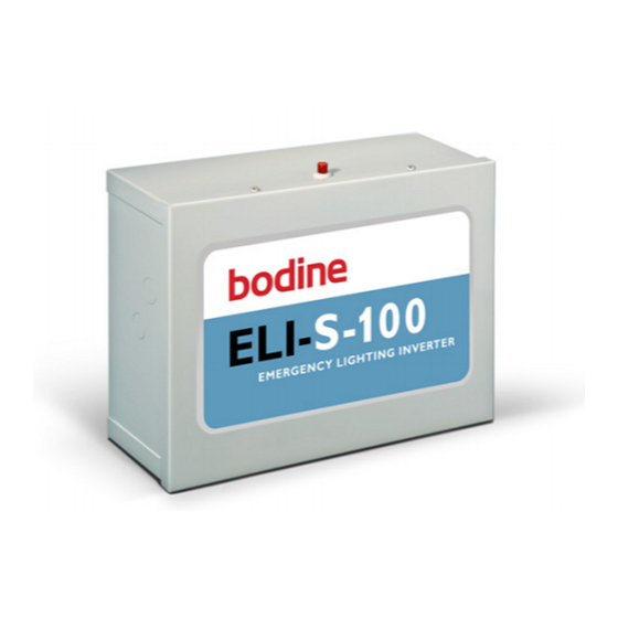
ELI-S-100
WITH DIMMING CAPABILITIES
Installation and Operation Instructions
ELI SERIES EMERGENCY LIGHTING INVERTERS
! IMPORTANT SAFEGUARDS !
READ AND FOLLOW ALL SAFETY INSTRUCTIONS
1. Caution:
• High voltage will be present on the output wires and terminals if batteries are installed and inverter
connector is joined or if AC power is supplied to the switched and unswitched terminal.
• Ensure input and output primary wiring connections are made to the proper terminals. Damage to product
may occur if miswired.
• Ensure load voltage requirements (120 or 277 Vac) match the output ratings of this product or damage to
the load devices may occur.
• The batteries should be installed and charged within 8 months of manufacture's date code. See step #6
for date code information.
2. This product is suitable for use in damp locations where the ambient temperature is 0°C through 40°C,
depending on load. See output ratings on product label for details. This product is not suitable for heated
air outlets and wet or hazardous locations.
3. Make sure all connections are in accordance with the National Electrical Code or Canadian Electrical Code
and any local regulations.
4. To reduce the risk of electric shock, disconnect both the normal and emergency power supplies and the
inverter connector of the emergency lighting inverter before servicing.
5. Do not install near gas or electric heaters.
6. An unswitched AC power source is required. The AC voltage rating of this equipment is specified on the
product label. Do not connect equipment to any other voltage.
7. Equipment should be mounted securely in locations and at heights where it will not be readily subjected to
tampering by unauthorized personnel.
8. The use of accessory equipment and replacement parts not recommended by the manufacturer may cause an
unsafe condition.
9. Do not use this equipment for other than its intended purposes.
10. The battery is field replaceable. Contact manufacturer for information on replacement. Use caution when
replacing battery. Dispose of the battery properly. Do not incinerate.
SAVE THESE INSTRUCTIONS
THIS PRODUCT INCLUDES RECHARGEABLE LEAD-ACID BATTERIES.
THE BATTERIES MUST BE RECYCLED OR DISPOSED OF PROPERLY.
© Philips Emergency Lighting
WHEN USING ELECTRICAL EQUIPMENT, BASIC SAFETY
PRECAUTIONS SHOULD ALWAYS BE FOLLOWED,
INCLUDING THE FOLLOWING:
Ni - Cd
06/21/17
Advertisement
Table of Contents

Summary of Contents for Philips Bodine ELI Series
-
Page 1: Installation And Operation Instructions
10. The battery is field replaceable. Contact manufacturer for information on replacement. Use caution when replacing battery. Dispose of the battery properly. Do not incinerate. SAVE THESE INSTRUCTIONS Ni - Cd THIS PRODUCT INCLUDES RECHARGEABLE LEAD-ACID BATTERIES. THE BATTERIES MUST BE RECYCLED OR DISPOSED OF PROPERLY. 06/21/17 © Philips Emergency Lighting... - Page 2 INSTALLATION WARNING: TO PREVENT HIGH VOLTAGE FROM BEING PRESENT ON THE COMMON OUTPUT AND HOT OUTPUT LEADS PRIOR TO INSTALLATION, INVERTER CONNECTOR MUST BE OPEN. JOIN INVERTER CONNECTOR INSIDE THE CASE AFTER INSTALLATION IS COMPLETE AND AC POWER IS SUPPLIED. NOTE: Make sure the inverter connector is closed before screwing the front cover to the case.
- Page 3 ILLUSTRATION 2 PRIMARY WIRING CONNECTIONS UnSwHot SwHot COM GND OutHot OutCom COM OUTPUT OUTPUT CONNECTIONS HOT OUTPUT GROUND COMMON AC POWER SOURCE INPUT SWITCHED HOT UNSWITCHED HOT ENCLOSURE GROUNDING CAUTION: • Ensure input and output primary wiring connections are made to the proper terminals. Damage to product may occur if miss wired.
- Page 4 Reverse this process to install the new batteries. Remember to join the inverter connector prior to reinstalling the lid. The charging indicator light should be illuminated once unswitched AC power is restored. Use only Philips Bodine part number PRT00133 as replacement batteries.
-
Page 5: Wiring Diagram
STEP #7 JOIN THE INVERTER CONNECTOR & APPLY POWER > After installation is complete, apply AC power and join the inverter connector inside the case then screw the front cover to the case. > At this point, power should be connected to both the AC ballast and the ELI-S-100, and the Charging Indicator Light on the test switch should illuminate indicating the battery is charging.


Need help?
Do you have a question about the Bodine ELI Series and is the answer not in the manual?
Questions and answers