Advertisement
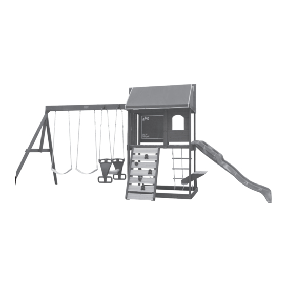
P I N E R I D G E I V P L A Y S Y S T E M
A S S E M B L Y
Pine Ridge 3
20' 6"
Play System dimension with
safety allowance: 32'6" x 20'
Prior to assembly, you MUST read the Owner's Manual for important safety warnings and details on installing a shock absorbing surface.
This unit's maximum fall height is 7.5 feet and is intended for a maximum of 7 users, ages 3 to 10 (110 lbs. per child).
12ft
8' 0"
For questions, assembly help or assistance with missing or defective parts:
North America
Solowave Design
375 Sligo Rd. West PO Box 10
Mount Forest, Ontario Canada
N0G 2L1
General Inquiries:
Toll Free: 1-877-966-3738
Email: support@solowavedesign.com
I N S T R U C T I O N S
Effective June 26/09
United Kingdom
General Inquiries:
Toll Free: 0870 145 2145
Email: info@selwoodproducts.co.uk
Other Countries:
Please refer to label affixed to outside of carton.
The 1-877 number on the Owners Manual &
Safety Instructions is for North America only.
3403230
F23230
8-10 Hrs
Advertisement
Table of Contents

Related Manuals for Solowave Big Backyard PINE RIDGE IV


Summary of Contents for Solowave Big Backyard PINE RIDGE IV
- Page 1 This unit’s maximum fall height is 7.5 feet and is intended for a maximum of 7 users, ages 3 to 10 (110 lbs. per child). For questions, assembly help or assistance with missing or defective parts: North America United Kingdom Solowave Design General Inquiries: 375 Sligo Rd. West PO Box 10 Toll Free: 0870 145 2145 Mount Forest, Ontario Canada Email: info@selwoodproducts.co.uk...
- Page 2 Important Information: Please ensure page is read. ABOUT OUR WOOD Solowave Design™ uses only Premium playground lumber, ensuring the safest product for your children’s use. Although great care has been taken in selecting the best quality lumber available, wood is a product of nature and susceptible to weathering (changes in the aesthetics of the wood).
-
Page 3: Tools Required
110˚ Shoulder Dowel NOTE: In the event that the thread of a Hex Bolt is exposed beyond the tee-nut, please disassemble, add Tenon Rail another flat washer to head of hex bolt and reassemble. © Solowave Design. All rights reserved. - Page 4 Wood Identification (Reduced Size Parts) Nominal Actual Before you assemble your fort, please identify and count your boards. Size Size Remember, wood is a product of nature and affected by changes in 2" x 6" 1 3/8" x 5 3/8" weather.
-
Page 5: Component Identification
Wood Identification (Reduced Size Parts) (1) Tarp Front (1 x 4 x 58-1/2") 3660713 (2) 2 x 2 x 12-1/2" Sl Brace 3660620 (1) Top Ridge (2 x 2 x 66") 3660753 (1) Top Window (1 x 6 x 23-1/2") (2) Seat Table Support (2 x 6 x 16-3/4") (1)SW Rail Block (2 x 4 x 5-3/8") 3660701... -
Page 6: Hardware Identification
HARDWARE IDENTIFICATION Before you start assembling your fort, be sure to sort, identify, and count all of the hardware. During Assembly DO NOT fully tighten bolts unless instructed. Fully tightened bolts may not allow for other hole alignments. IMPORTANT! Before children use the play center, make sure all hardware is tightened, all ground stakes are installed, and any remaining wood, hardware packaging materials are removed from the play area. - Page 7 HARDWARE IDENTIFICATION (Actual Size Parts) (38) #8 x 1-1/8" Wood Screw (110) #8 x 1-1/2" Wood Screw (22) #8 x 1/2" (22)#8 (2) #12 x 3/4" Pan Screw Flat Washer Pan Screw (16) #8 x 2-1/2" Wood Screw (14) #12 x 2" Pan Screw (6) #12 x 1"...
- Page 8 HAVE YOU SORTED, IDENTIFIED, AND COUNTED ALL YOUR HARDWARE, WOOD PIECES AND ACCESSORIES? THIS WILL ASSIST YOU IN YOUR ASSEMBLY. WHEN THE PARTS IDENTIFICATION IS COMPLETED, YOU ARE READY TO START ASSEMBLY. IF YOU NEED ASSISTANCE CONTACT THE CONSUMER RELATIONS DEPARTMENT AT NUMBER LISTED ON FRONT COVER.
- Page 9 HARDWARE LIST Swing & Slide Wall Assembly For the Slide Wall, assemble Ground Diagonal to Post; Roof Side, Floor End 2 pcs 1/4 x 5" Hex Bolt & Ground Side to Posts; Ground Diangonal to Ground Side. 18 pcs 1/4 x 2" Hex Bolt 20 pcs 1/4"...
-
Page 10: Hardware List
Front Wall Assembly HARDWARE LIST With the aid of helper, attach Floor Front, Ground Front, 1 pc 1/4x2" Hex Bolt Front Top to Walls created in Step 1. 2 pcs 1/4x5" Hex Bolt 4 pcs 1/4x4" Hex Bolt IMPORTANT! Make sure that Floor Front holes are 2 pcs 1/4x2-1/2"... - Page 11 HARDWARE LIST Attach Back Top and Floor Back to Side Walls. Loosely attach Centre Divider. Attach Rope Bottom by drilling 1/8" pilot holes using the board 2 pcs 1/4x4-1/2" Hex Bolt 2 pcs 1/4x4" Hex Bolt as a guide, first, then attach with Wood Screws. Board should 1 pc 1/4x1-1/2"...
- Page 12 Fort Floor Assembly HARDWARE LIST Attach Side Joist to Floor Back, using Hex Bolts & tighten. Insert notched Gap Boards flush with Floor Ends & attach 4 pcs 1/4x2-1/2" Hex Bolt to Floor Front & Side Joist with 1½" long Wood Screws. 4 pcs 1/4"...
- Page 13 HARDWARE LIST 20 pcs #8x1-1/8" Wood Screw WOOD PARTS LIST 1 pc 1x6x23-1/2" Top Window 4 pcs 1x6x23-1/2" CE Wall Boards (Stained) Attach CE Wall boards & Top Window using (12) Wood Screws, leaving maximum gap of 3" between deck & edge of bottom CE Wall board.
-
Page 14: Accessory List
HARDWARE LIST 2 pcs #8x1-1/8" Wood Screw 4 pcs #8x1-1/2" Wood Screw 12 pcs #8x1/2" Pan Screw 12 pcs #8 Flat Washer WOOD PARTS LIST 1 pc 1x2x25-1/2" Panel Frame 1 pc 1x4x31" Lower Chalk Wall ACCESSORY LIST 1 Chalk Wall (Tarp) Attach Panel Frame and Lower Chalk Wall with (4) Wood Screws. - Page 15 *Pre-drill pilot holes, with a 1/8" drill bit and evenly space the HARDWARE LIST drilled holes as shown in the Side View. Using (3)Pan Screws per Rock Rail, attach(2) Rock Sides to 6 pcs #12x2" Pan Screw the (2) Rock Rails. 28 pcs #8x1-1/2"...
- Page 16 HARDWARE LIST Center Rock Wall in opening at front of Fort. Drill 1/8" pilot holes then attach with (4) 2" Long Pan Screws (3/16" Flat Washers). 5 pcs 1/4x1-1/4" Pan Bolt 5 pcs 1/4" Barrel-Nut Attach rocks in desired locations with 5 pcs 3/16"...
- Page 17 Attach Gussets WOOD PARTS LIST •Drill 3/16" pilot holes into the swing side posts, using the Gusset hole as a guide. Fasten, using (1) Lag Screw with flat washer. 2 pcs 2x4x13" Gusset 1 pc 2x3x59¼" Roof Mount •Using (3) 1-1/2" Wood Screws per side, attach the Gussets to the 1 pc 2x4x59¼"...
- Page 18 Swing End Assembly WOOD PARTS LIST •Fasten the Triangle Plates to the insides of the Single Beams. •Attach (1) 1/4 x 5½" Hex Bolts to each end of each beam. 2 pcs 2x6x91¾" Single Beam 2 pcs 2x4x92½" Sw Post NOTE: These bolts are required for strength, they do not attach to 1 pc 2x4x50½"...
-
Page 19: Front View
Attach Swing & Glider Hangers HARDWARE LIST •Attach (4) Swing Hangers to the Single Beams. Stagger 4 Swing Hangers hangers 2 per beam. 2 Glider Hangers •Using (2) lag screws per hanger, attach the Glider Hanger to 4 pcs 3/8x3" Lag Screw the underside of the beams. - Page 20 MOVE THE FORT TO ITS FINAL LOCATION & TIGHTEN ALL HARDWARE LIST HEX BOLTS FROM PREVIOUS STEPS •With the aid of a helper, secure Single Beam to the Swing Post 2 pcs 5/16x4½" Hex Bolt 2 pcs 5/16x2" Hex Bolt frame.
- Page 21 WOOD PARTS LIST Roof & Wall Assembly •Using (2) #8 x 3" Wood Screws, fasten into ends of Roof 6 pcs #8x1/2" Truss Screw Mounts using holes in Top Ridge as a guide. 16 pcs #8x1-1/8" Wood Screw •Using (16) #8 x 1-1/8" Wood Screws, attach (4) CE Gap 2 pcs #8x3"...
- Page 22 Centre and hang Canopy over Roof Ridge & attach (2) pan screws HARDWARE LIST with washers on the top of roof. Stretch Canopy to the front & attach with (4) evenly spaced screws with washers at the hem. 10 pcs #8x1/2"Pan Screw 10 pcs #8"Flat Washer Do the same at the back.
- Page 23 WOOD PARTS LIST Attach Seat/Table Supports on the inside of the Fort Posts on the slide side. Drill (2) pilot 2 pcs 2x6x16¾" Seat Table Support holes approximately 18" up from the ground then 1 pc 5/4x6x34¼" Cafe Seat attach only (2) 1/4 x 3" Lag Screws (1/4" Washer) HARDWARE LIST through center holes of Supports.
- Page 24 Make sure the seat is level and under the fort. WOOD PARTS LIST Children seated at the table should be facing out. 2 pcs 1x6x34-1/4" CE Table Top Drill 1/8" holes using the (4) remaining factory holes as guides. Holes should be centered on the Post. HARDWARE LIST Secure with the (4) 1/4 x 3"...
- Page 25 WOOD PARTS LIST Mount slide to deck, centred on opening. 2 pcs 2x2x12-1/2" Sl Brace First drill 1/8" pilot holes through deck into centre of HARDWARE LIST Slide Brace and attach with screws 4 pcs #12x2" Pan Screw 1 pc #12x1" Pan Screw ACCESSORY LIST 1 Slide Note: Place slide in the centre of the...
- Page 26 Stakes Installation WOOD PARTS LIST •Use a scrap wood piece in between the top of the Ground Stake & 5 pcs 2x2x14" Ground Stakes the Sledge Hammer to protect the stake from damage. •Stakes are to be secure to the posts and the ground. HARDWARE LIST •Firmly anchor unit to ground before use.
- Page 27 ACCESSORY LIST 1Glider Seat 4 Glider Ropes with Chain 2 Glider Handles 2 Belt Swings HARDWARE LIST 2 pcs 5/16x6" Hex Bolt 4 pcs 5/16" Flat Washer 8 pcs 5/16" Flat Washer-zinc 5/16 x 3¾" 6 pcs 5/16" Lock Nut-zinc Eyebolt •Assemble Glider Handles to Seat as shown with 6"...
-
Page 28: Product Number
ATTENTION *During peak play season, periodically check and re-tighten all hex bolts, lag screws, and wood screws to ensure safety. Do not over-tighten to avoid crushing wood. *Thoroughly read instructions and the owners manual before using play center. *Maintain assembly instructions for future reference. FILL THIS OUT BEFORE YOU DISCARD YOUR CARTONS.
Need help?
Do you have a question about the Big Backyard PINE RIDGE IV and is the answer not in the manual?
Questions and answers