Advertisement
Available languages
Available languages
Quick Links
Download this manual
See also:
User Manual
Jetter AG
Gräterstraße 2
D-71642 Ludwigsburg E-Mail - Hotline:
Germany
Artikel-Nr.: 60879282 | Version 1.12
1 x
10001018 JVM-104-K00-O01
1 x
60879282 Installationsanleitung
1 x
60880138 Montage-Kit
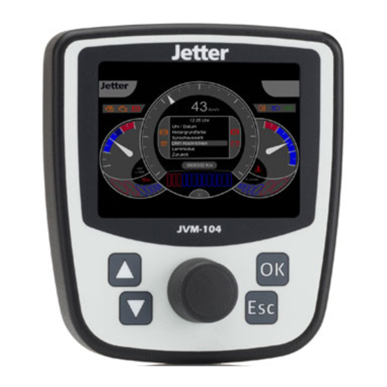
JVM-104
Bediengerät
Kontakte:
E-Mail - Vertrieb: sales@jetter.de
Telefon - Hotline: +49(0)7141/2550-
Installationsanleitung
Mai 2015 / Printed in Germany
Laden Sie die Betriebsanleitung
von www.jetter.de unter
Support > Downloads herunter.
Lieferumfang
Zubehör
hotline@jetter.de
444
Advertisement

Subscribe to Our Youtube Channel
Related Manuals for Jetter JVM-104


Summary of Contents for Jetter JVM-104
- Page 1 JVM-104 Bediengerät Jetter AG Kontakte: Gräterstraße 2 E-Mail - Vertrieb: sales@jetter.de D-71642 Ludwigsburg E-Mail - Hotline: hotline@jetter.de Germany Telefon - Hotline: +49(0)7141/2550- Installationsanleitung Artikel-Nr.: 60879282 | Version 1.12 Mai 2015 / Printed in Germany Laden Sie die Betriebsanleitung von www.jetter.de unter Support >...
- Page 2 Abmessungen 18,7 51,7 Die Abbildung zeigt die Maße in Millimeter Platzbedarf Die Abbildung zeigt das Maß in Millimeter...
- Page 3 Montageausschnitt erstellen 105,2 + 0,3 42,5 26,6 Beschreibung Beschreibung 1 Umriss der Frontplatte 2 Öffnung...
- Page 4 Gerät montieren Beschreibung Beschreibung 1 JVM-104 4 4 x Bohrung zur Befestigung des JVM-104 2 Montageplatte mit 5 4 x selbstfurchende Öffnung für das Schraube Bediengerät Schraubenmaß: 4 x 9 + t 3 Winkel zur Befestigung Anzugsmoment: mit Öffnung für die 1,6 Nm ±...
- Page 5 Schnittstellen und Anschlüsse im Überblick Beschreibung Bohrung zur Befestigung des Bediengeräts, max. 12 mm tief Typenschild 8-poliger M12-Stecker Druckausgleichselement...
- Page 6 Anschlussbeschreibung M12-Stecker Sicht auf die Geräterückseite: Beschreibung 1 Versorgungsspannung UB für die Logik des Geräts Spannung: DC 12 V oder DC 24 V Maximaler Strom: 2 A 2 Frei 3 Steuersignal Zündung POWER_ON 4 Frei 5 CAN_L 6 Bezugspotenzial GND 7 CAN_H 8 Abschirmung Gegenstück zum 8-poligen M12-Stecker...
-
Page 7: Technische Daten
Technische Daten Display: 3,5"-TFT-Farbdisplay, 320 x 240 Pixel Bedienung: 4 Funktionstasten mit Hintergrundbeleuchtung, Digipot, Touch Betriebssystem: Microsoft Windows CE 6.0 Betriebstemperatur: -20 °C ... +60 °C Lagertemperatur: -20 °C ... +70 °C Schutzart: Frontseitig: IP65 Rückseitig: IP65 Schnittstellen: 1 x CANopen® Zulässiger DC 8 V ... - Page 9 Germany Phone - Hotline: +49(0)7141/2550- Installation Manual Item # 60879282 | Revision 1.12 May 2015 / Printed in Germany Download the user manual from www.jetter.de, Support > Downloads. Scope of delivery 10001018 JVM-104-K00-O01 60879282 Installation manual Accessories 60880138 Fastening kit...
- Page 10 Dimensions 18.7 51.7 (All dimensions in mm) Required space (All dimensions in mm)
- Page 11 Cutting out the installation opening 105.2 + 0.3 42.5 26.6 Description Description Outline of the front Opening panel...
- Page 12 Mounting Description Description JVM-104 4 x screw holes for screwing down the JVM-104 Panel with opening for 4 x self-tapping screw accommodating the HMI Screw size: 4 x 9 + t Fastening bracket with Tightening torque: opening for connector 1.6 Nm ± 10 %...
- Page 13 Overview - Interfaces and connections Description Screw holes for fastening the HMI. Max depth: 12 mm Nameplate 8-pin male connector M12 Pressure compensation membrane...
- Page 14 Male connector M12 - Pin assignment View to the rear side of the HMI: Description 1 Power supply UB for logic circuits Voltage: DC 12 V or DC 24 V Maximum current: 2 A 2 Unassigned 3 Ignition control signal POWER_ON 4 Unassigned 5 CAN_L 6 Reference potential (GND)
-
Page 15: Technical Specifications
Technical specifications Display: 3.5" TFT color display, (320 x 240 pixel) Operation: 4 function keys with background lighting, digipot, touch Operating system: Microsoft Windows CE 6.0 Operating temperature: -20 °C ... +60 °C Storage temperature: -20 °C ... +70 °C Degree of protection: Front panel: IP65 Rear panel: IP65...
Need help?
Do you have a question about the JVM-104 and is the answer not in the manual?
Questions and answers