
Related Manuals for Xylem LOWARA SMB /SVE Series

Summary of Contents for Xylem LOWARA SMB /SVE Series
- Page 1 SMB Booster set SMB../SVE, SMB../VME, SMB../HME Installation, Operation and Maintenance Manual Cod.001086038EN rev.C ed.03/2018...
-
Page 2: Table Of Contents
en – Original instructions Table of Contents Introduction and Safety ............................5 Introduction ................................ 5 Safety ................................5 1.2.1 Danger levels and safety symbols ........................ 5 1.2.2 User safety ..............................6 1.2.3 General safety rules ............................7 1.2.4 Protection of the environment ........................8 1.2.5 Sites exposed to ionizing radiations ...................... - Page 3 en – Original instructions 5.2.3 Starting the booster set ..........................22 Maintenance ................................24 Maintenance of the control panel and frequency converters ................24 Maintenance of the diaphragm pressure tank ....................24 Troubleshooting ..............................25 The booster set is off ............................25 Motor does not start ............................
- Page 4 en – Original instructions...
-
Page 5: Introduction And Safety
en – Original instructions 1 Introduction and Safety 1.1 Introduction Purpose of this manual The purpose of this manual is to provide necessary information for: Installation Operation Maintenance CAUTION: Before installing and using the product, make sure that you read and fully understand this manual in all its parts. -
Page 6: User Safety
en – Original instructions Special symbols Some hazard categories have specific symbols, as shown in the following table: Symbol Description Electrical hazard Magnetic hazard Hot surface hazard Ionizing radiation hazard Potentially explosive atmosphere hazard (ATEX EU Directive) Cut and abrasion hazard Crushing hazard (limbs) Other symbols Symbol... -
Page 7: General Safety Rules
en – Original instructions Inexperienced users WARNING: FOR THE EUROPEAN UNION This appliance can be used by children aged from 8 years and above and persons with reduced physical, sensory or mental capabilities or lack of experience and knowledge if they have been given supervision or instruction concerning use of the appliance in a safe way and understand the hazards involved. -
Page 8: Protection Of The Environment
If the product needs to be despatched, inform the carrier and the recipient accordingly, so that appropriate safety measures can be put in place. 1.3 Spare parts When contacting Xylem or the Authorised Distributor to request technical information or spare parts, always indicate the product type and code. 1.4 Product warranty... -
Page 9: Transportation And Storage
Accept the goods with reserve, indicating any findings on the transport document, or Reject the goods, indicating the reason on the transport document. In both cases, promptly contact Xylem or the Authorised Distributor from whom the product was purchased. -
Page 10: Storage
en – Original instructions Figure 1: Lifting 2.2 Storage The product must be stored: In a covered and dry place Away from heat sources Protected from dirt Protected from vibrations At an ambient temperature between -25°C and +55°C (-13°F and 131°F), and relative humidity between 5% and 95%. -
Page 11: Technical Description
en – Original instructions 3 Technical Description 3.1 Designation Booster set consisting of one (SMB10) or more identical variable speed vertical or horizontal multistage non-self priming pump units (SMB20, SMB30) connected in parallel. The pump units are mounted on a shared base with suction and delivery manifolds, on-off valves, non-return valves, pressure gauge, pressure transmitters and a single-phase or three-phase control panel. -
Page 12: Distribution Panel
en – Original instructions 1. Series 2. Number of pump units [10] = 1 pump unit [20] = 2 pump units [30] = 3 pump units 3. Non-return valve [_] = Delivery side [RA] = Suction side 4. Certificate of drinking water A = WRAS, ACS, M.D.174 unit B = ACS, M.D.174... -
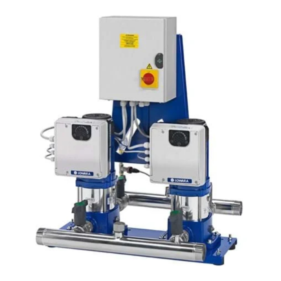
Page 13: Design And Layout
en – Original instructions 3.3 Design and layout Booster set in standard configuration Figure 5: Booster set Position Description Q.ty number Distribution panel E series pump units (e-SM units) Base Priming connection Anti-vibration foot 2 x n Suction manifold On-off valve on suction line Non-return valve On-off valve on delivery line Pressure sensor... -
Page 14: Intended Use
en – Original instructions 3.4 Intended use The product can be used to pump: Cold water Hot water Always observe the limits indicated in the Technical Data chapter. The variable speed pump units installed in the SMB booster sets are suitable for the following applications: ... -
Page 15: Installation
en – Original instructions 4 Installation 4.1 Mechanical installation 4.1.1 Installation area DANGER: Potentially explosive atmosphere hazard The operation of the booster set in environments with potentially explosive atmospheres or with combustible dusts (e.g.: wood dust, flour, sugars and grains) is strictly forbidden. WARNING: ... -
Page 16: Guidelines For Mechanical Installation
en – Original instructions 4.1.2 Guidelines for mechanical installation The arrows on the pump unit body indicate the flow and the rotation direction of the motor The standard rotation direction of the motor is clockwise (looking at the fan cover) ... -
Page 17: Guidelines For Hydraulic Installation
en – Original instructions Figure 9: Multi-pump system 1. e-SM pump unit with motor 4. On-off valve 7. Pressure gauge 2. Diaphragm pressure tank 5. Non-return valve 8. Pressure sensor 3. Distribution panel 6. Low water control 9. Drain tap 4.2.1 Guidelines for hydraulic installation ... -
Page 18: Electrical Installation
en – Original instructions 4.3 Electrical Installation DANGER: Electrical hazard The connection to the electric power supply must be completed by an electrician possessing the technical-professional requirements outlined in the current regulations. For the electrical connections, refer to the wiring diagram in the control panel. 4.3.1 Electrical requirements Local directives prevail on the specific requirements indicated below. -
Page 19: Wire Types And Ratings
en – Original instructions Grounding (earthing) DANGER: Electrical hazard Always connect the external protection conductor to the ground terminal before attempting to make any other electrical connections All the electrical equipment must be grounded (earthed); this includes the booster set and its equipment. -
Page 20: Protection Against Dry Running
en – Original instructions 4.3.5 Protection against dry running The standard control panel can be connected to a common float for the open tanks, or to a minimum pressure pressure switch on the suction side (recommended value: 0.2-0.4 bar). When the minimum pressure conditions are restored, the pump units start automatically. -
Page 21: Use And Operation
duty points insisting on maximum power of the booster set persisting undervoltage of mains, the life of the booster set may be jeopardised and/or derating may occur: for further information contact Xylem or the Authorised Distributor. 5.1 Wait times WARNING: Electrical hazard Contact with electric components may cause death, even after the booster set has been switched off. -
Page 22: Adjusting The Frequency Converter
en – Original instructions Figure 10 shows the operating curves in the case of two pump units in pressure adjustment mode. The tank supplies water to meet the demand of the final user. The first pump unit starts when the pressure drops below the PS value; the speed is adjusted to keep the pressure constant as demand increases. - Page 23 en – Original instructions How to change the settings With the booster set running, follow the instructions below on how to change the settings within the maximum pressure limits of the pump units or system or both: 1. Establish the required pressure value. 2.
-
Page 24: Maintenance
en – Original instructions 6 Maintenance DANGER: Electrical hazard Before attempting to use the unit, check that it is unplugged and that the pump unit and the control panel cannot restart, even unintentionally. This also applies to the auxiliary control circuit of the pump unit. -
Page 25: Troubleshooting
Observe the safety requirements in the chapters on Use and Operation and Maintenance If a fault cannot be corrected or is not mentioned, contact Xylem or the Authorised Distributor. The frequency converter saves the last alarms that have occurred. Refer to the instructions on use of the frequency converter for the types of fault and how to check the last alarms that have occurred. -
Page 26: The Motor Runs But No Water Is Delivered
en – Original instructions 7.5 The motor runs but no water is delivered Cause Remedy No water on suction side or inside 1. Fill (prime) the pump unit or suction pipe the pump unit 2. Open the on-off valves Air inside the suction pipe or pump 1. -
Page 27: Tripping Of The Differential Protection
en – Original instructions 7.10 Tripping of the differential protection Cause Remedy Damaged motor Replace the motor Power cable of the motor faulty or Replace the cable worn Differential switch not compliant Replace the differential switch with the specifications Differential current too high Contact a qualified technician to have the electrical system modified 7.11 The pump unit runs at maximum speed without stopping Cause... -
Page 28: Technical Data
en – Original instructions 8 Technical Data Table 2: Electrical, environmental and installation specifications, booster set in standard version Model of booster set Control panel power supply Input Input frequency [Hz] 50/60 ± 2 Main supply L1 L2 L3 Nominal input voltage of the control panel [V] 230 ±... -
Page 29: Dimensions And Weights
– Original instructions 8.1 Dimensions and weights Booster set: refer to the technical catalogue or contact Xylem or the Authorised Distributor. Pump units in the Smart Pump Range: refer to the Installation, Operation and Maintenance Manual. 9 Declarations 9.1 EC Declaration of Conformity (Original) - Page 30 en – Original instructions...
- Page 31 Xylem Service Italia S.r.l. Via Vittorio Lombardi 14 36075 – Montecchio Maggiore (VI) - Italy www.xyleminc.com/brands/lowara Lowara is a trademark of Xylem Inc. or one of its subsidiaries. © 2017 Xylem, Inc.
Need help?
Do you have a question about the LOWARA SMB /SVE Series and is the answer not in the manual?
Questions and answers