aqua technix Aqua AQ 280 Operation Manual
Sand filter systems
Hide thumbs
Also See for Aqua AQ 280:
- Original operation manual (144 pages) ,
- Original operation manual (184 pages)
Table of Contents
Advertisement
Available languages
Available languages
Quick Links
Advertisement
Chapters
Table of Contents

Related Manuals for aqua technix Aqua AQ 280


Summary of Contents for aqua technix Aqua AQ 280
- Page 1 AQUA Sandfilteranlage AQ 280, AQ 330, AQ 400 AQUA sand filter systems AQ 280, AQ 330, AQ 400 Hauptstraße 1-3 • 91233 Neunkirchen a. Sand Tel. 09123-949-950 • Fax 09123-949-951 info@aquatechnix.de • www.aquatechnix.de 03/2014 VG 766.2050.051 1’ AHIR/SN...
- Page 2 Inhaltsverzeichnis | Original operation manual Inhaltsverzeichnis | Original operation manual DE Originalbetriebsanleitung für ........ 3 EN Original operation manual for ......30 2 DE│EN VG 766.2050.051 03/2014...
- Page 3 Inhaltsverzeichnis | Original operation manual Original Betriebsanleitung für AQUA Sandfilteranlage Hauptstraße 1-3 • 91233 Neunkirchen a. Sand Tel. 09123-949-950 • Fax 09123-949-951 info@aquatechnix.de • www.aquatechnix.de 03/2014 VG 766.2050.051 DE 3...
-
Page 4: Table Of Contents
Inhaltsverzeichnis Inhaltsverzeichnis Filterdatenblatt ................6 Zu diesem Dokument ..............7 Umgang mit dieser Anleitung ........... 7 Mitgeltende Dokumente ............7 2.2.1 Symbole und Darstellungsmittel ........7 Sicherheit ..................8 ... - Page 5 Instandhaltung ................29 Alle Rechte vorbehalten. Inhalte dürfen ohne schriftliche Zustimmung von AQUA TECHNIX GmbH weder verbreitet, vervielfältigt, bearbeitet noch an Dritte weitergegeben werden. Dieses Dokument sowie alle Dokumente im Anhang unterliegen keinem Änderungsdienst! Technische Änderungen vorbehalten! 03/2014 VG 766.2050.051...
-
Page 6: Filterdatenblatt
1 Filterdatenblatt Filterdatenblatt Förderstrom Filter- Gewicht Filter Sand Q (m³/h) schlüsse fläche (kg) (mm) (kg) (mm) (m²) V=40 m/h V=50 m/h ohne Pumpe Tülle Ø 280 0,06 Ø 38 Tülle Ø 330 0,08 Ø 38 Tülle Ø 400 0,12 Ø 38 Ø... -
Page 7: Zu Diesem Dokument
2 Zu diesem Dokument Zu diesem Dokument Umgang mit dieser Anleitung Die Filteranlage wurde nach den anerkannten Regeln der Technik hergestellt und geprüft. Dennoch können bei unsachgemäßer Verwendung, unzureichender Wartung oder unzulässigen Eingriffen Gefahren für Leib und Leben bzw. materielle Schäden entstehen. Vor Gebrauch aufmerksam lesen. -
Page 8: Sicherheit
3 Sicherheit Sicherheit Bestimmungsgemäße Verwendung Die Filteranlage dient zum Reinigen des Schwimmbadwassers. Zur Verwendung gehört die Beachtung folgender Informationen: Diese Anleitung Pumpenbetriebsanweisung Eine andere oder darüber hinausgehende Verwendung ist nicht bestimmungsgemäß (z. B. höhere Wassertemperatur, Einsatz von brennbaren, giftigen, aggressiven oder leicht flüchtigen Medien). 3.1.1 Mögliche Fehlanwendungen Betrieb der Anlage außerhalb des Einsatzbereichs, zum Beispiel bei... -
Page 9: Schutzeinrichtungen
3 Sicherheit Schutzeinrichtungen Hineingreifen in bewegliche Teile (z. B. Lüfterrad) kann schwere Verletzungen verursachen. Pumpe nur mit Berührungsschutz betreiben. Bauliche Veränderungen und Ersatzteile Umbau oder Veränderungen kann Betriebssicherheit beeinträchtigen. Filteranlage nur in Absprache mit dem Hersteller umbauen oder verändern. Nur Original-Ersatzteile oder Zubehör verwenden, das vom Hersteller autorisiert ist. -
Page 10: Elektrische Energie
3 Sicherheit 3.7.3 Elektrische Energie Vor Arbeiten an Pumpe WARNUNG oder Motor Stromzufuhr zum Motor Filterpumpe führt trennen gefährliche Spannung, die zu Schock, Verbrennungen oder zum Tod führen kann Bei Arbeiten an der elektrischen Anlage besteht durch die feuchte Umgebung erhöhte Stromschlaggefahr. Ebenso kann eine nicht ordnungsgemäß... -
Page 11: Störungen
3 Sicherheit Störungen Bei Störungen Anlage sofort stilllegen und ausschalten. Alle Störungen umgehend beseitigen lassen. Festsitzende Pumpe Wird eine festsitzende Pumpe mehrmals hintereinander eingeschaltet, kann der Motor beschädigt werden. Folgende Punkte beachten: Pumpe nicht mehrmals hintereinander einschalten. Motorwelle durchdrehen. Pumpe reinigen. Vermeidung von Sachschäden Störung Mögliche Ursache... -
Page 12: Beschreibung
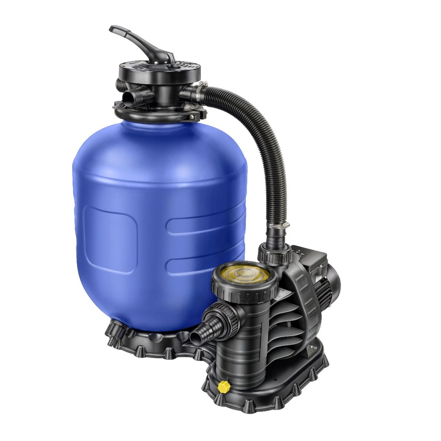
4 Beschreibung Beschreibung Aufgabe Die Filteranlage wird zum Reinigen von Schwimmbeckenwasser genutzt, durch einen speziellen Quartzsand wird das Becken mechanisch von Schwebstoffen und Verunreinigungen befreit. Komponenten (1) Filterbehälter (2) 6-Wege-Ventil (3) Pumpe (4) Entleerungsventil Funktion Die Pumpe (3) saugt das ungefilterte Wasser aus dem Schwimm- becken. -
Page 13: Erklärung Des 6-Wege-Ventils
4 Beschreibung Erklärung des 6-Wege-Ventils Die einzelnen Funktionen/Stellungen: Stellung Funktion Filtern Zu filterndes Schwimmbadwasser wird durch Filter und Quartzsand gepumpt (Betriebszustand) Rückspülen Stellung zum Reinigen des Filtersystems Schwimmbeckenwasser wird entgegengesetzt durch den Filter gepumpt Schmutzwasser wird in den Kanal geleitet Nachspülen Filterung in den Kanal Restschmutz in Leitungen der Anlage nach... -
Page 14: Installation
5 Installation Installation Montageanleitung 5.1.1 Benötigte Werkzeuge Rohrzange Schraubendreher Gummihammer Handsäge Schneidmesser 5.1.2 Entleerungsventil Das Entleerungsventil (Pos. Nr. 21-27) wird an den Filterbehälter (2) montiert. Hierzu schieben O-Ring (21) über Sägezahngewinde, sowie den O-Ring (24) über das Gewinde G 3/4", vom Ventil (22). -
Page 15: Explosionszeichnung
5 Installation 5.1.3 Explosionszeichnung 03/2014 VG 766.2050.051 DE 15... -
Page 16: Stückliste
5 Installation 5.1.4 Stückliste AQUA Filter Ø 280: Ø 330: Ø 400: Teil Benennung Artikel-Nr. Filterfuß AQUA Filter 2670000001 Filterbehälter AQUA 2670000002 Filter Ø 280 Filterbehälter AQUA 2670000003 Filter Ø 330 Filterbehälter AQUA 2670000004 Filter Ø 400 Filtersieb mit Rohr kpl. 2670000408 Filtersieb mit Rohr kpl. -
Page 17: Montage Der Einzelnen Komponenten
5 Installation 5.1.5 Montage der einzelnen Komponenten Positionieren Sie zunächst den Filterbehälter (2) waagrecht im Filter- fuß (1). Richten Sie die Filterpumpe (40) auf dem Filterfuß (1) aus, sodass der Verbindungsrohr (4) zum 6-Wege-Ventil (10) sich gut anbauen lässt. Mit den beigelegten selbstschneidenden Schrauben (30) und den Unterlegscheiben (29) wird die Pumpe auf der Filterpalette (1) festgeschraubt. -
Page 18: Befüllen Des Behälters Mit Quartzsand
5 Installation Befüllen des Behälters mit Quartzsand Richtige Körnungsangabe verwenden: Ansonsten verschlechtert eine zu große Körnung die Filterqualität und eine zu kleine Körnung hat zur Folge das der Sand mit ins Becken gespült wird. Ideale Körnung: 0,4 mm bis 0,8 mm Der Filterbehälter (2) soll mit ca. -
Page 19: Quartzsand
5 Installation Nehmen Sie die Schutztüte ab und richten Sie das Rohr mittig aus. Durch probeweises Aufsetzen des Ventils (10), prüfen Sie ob das Rohr (4) richtig in der Mitte steht. Nun müssen Sie wieder die Schutztüte über das Rohr (4) stecken und die Restsandmenge auffüllen. Positionierung Steigrohr zum 6-Wege-Ventil Jetzt kann endgültig das 6-Wege-Ventil (10) auf das Steigrohr (4) - Page 20 5 Installation Aufsetzen des Ventils Ausrichten des Ventils 20 DE VG 766.2050.051 03/2014...
-
Page 21: Anschluss Der Sandfilteranlage An Das Becken
5 Installation Anschluss der Sandfilteranlage an das Becken Verbinden Sie den Sauganschluss der Pumpe mit einem Schlauch zum Becken. Außerdem müssen Sie den Ventilanschluss "Becken" mit der Einlaufdüse am Beckenrand verbinden. Schließen Sie noch den Ventilanschluss "Kanal" an den Kanal an. gem. -
Page 22: Elektrischer Anschluss
5 Installation Elektrischer Anschluss WARNUNG! Stromschlaggefahr durch unsachgemäßen Anschluss! VDE- und EVU-Vorschriften des Energieversorgungsunternehmens beachten. Anlagen für Schwimmbecken und deren Schutzbereiche gem. DIN VDE 0100-702 installieren. Trennvorrichtung zur Unterbrechung der Spannungsversorgung (min. 3 mm Kontaktöffnung pro Pol) installieren. Stromkreis mit einer Fehlerstromschützeinrichtung ≤... -
Page 23: Inbetriebnahme
6 Inbetriebnahme Inbetriebnahme Beschädigung der Pumpe durch Trockenlauf! Sicherstellen, dass Pumpe immer mit Wasser gefüllt ist. Pumpe auf Leichtgängigkeit prüfen Nach längerer Stillstandszeit muss die Pumpe im ausgeschalteten und spannungsfreien Zustand auf Leichtgängigkeit geprüft werden. Schraubendreher in den Schlitz am Motorwellenende (Lüfterseite) stecken und durchdrehen. -
Page 24: Weitere Maßnahmen
6 Inbetriebnahme Weitere Maßnahmen Maßnahme Erklärung Der Quartzsand ist bei der Neubefüllung auszuwaschen. 1. 6-Wege-Ventil (10) in Stellung "NACHSPÜLEN" Filterpumpe einschalten 2. Nach Beginn der Wasserförderung ca. 30 Sek. Wasser in den Behälter und Kanalisation leiten. 3. 6-Wege-Ventil (10) in Stellung "RÜCKSPÜLEN" Filterpumpe einschalten Quartzsand 4. - Page 25 6 Inbetriebnahme Maßnahme Erklärung Betriebszeit des Filters ist von Schwimmbeckeninhalt, Belegung, Wetter und Chemikalien abhängig In 24 Std. ein bis zwei mal umwälzen. z. B.: Beckeninhalt: 10 m³, soll 2 mal umgewälzt werden, so müssen 20 m³ befördert werden, pro Stunde Einstellen leistet die Pumpe 6 m³, also muss der Filter der Filterzeit...
-
Page 26: Regelmäßiges Rückspülen
7 Regelmäßiges Rückspülen Regelmäßiges Rückspülen Die Filterrückspülung sollte je nach Belastung, bzw. aus hygienischen Gründen mindestens einmal pro Woche erfolgen. Bei höherer Beckenbelastung sind die Rückspülintervalle zu verkürzen! Achtung: Bitte nach dem Rückspülen mit Frischwasser den fehlenden Wasserstand im Schwimmbecken nachfüllen! Rückspülen 6-Wege-Ventil (10) in Stellung "RÜCKSPÜLEN"... -
Page 27: Störungen
8 Störungen Störungen Übersicht Störung Mögliche Abhilfe Ursache Pumpe saugt Vorfilter ist nicht mit Füllen bis min. Höhe nicht Wasser gefüllt Sauganschluss selbstständig Luft wird angesaugt Saugleitung muss an, bzw. dicht sein; Wasser- Ansaugzeit ist stand bis Mitte sehr lang Skimmeröffnung Müssen gereinigt Verschmutzung der... - Page 28 8 Störungen Störung Mögliche Abhilfe Ursache Zu viel Sandfüllmenge zu groß Füllmenge, Quartzsand (Füllmenge Seite 19) Volumenstrom wird beim reduzieren Rückspülen aus Füllniveau stellt sich dem Filter in beim Rückspülen von den Kanal selbst ein gespült (Sandverluste abfangen) Pumpe läuft Stromleitung nicht unter Unter Spannung nicht von selbst...
-
Page 29: Instandhaltung
9 Instandhaltung Instandhaltung Vor Instandhaltungsarbeiten alle Absperrarmaturen schließen und Leitungen entleeren. Wann? Was? Regelmäßig Je nach Verschmutzungsgrad muss der Skimmer und der in der Pumpe eingebaute Vorfilter gereinigt werden Jährlich Einmal jährlich Füllhöhe und Beschaffenheit des FilterQuartzsandes prüfen bei Klumpenbildung erneuern Bei Frostgefahr Filterbehälter, Pumpe, frostgefährliche Leitungen durch Entleerungsschraube am... - Page 30 About this document Original operation manual for AQUA sand filter systems Hauptstraße 1-3 • 91233 Neunkirchen a. Sand Tel. 09123-949-950 • Fax 09123-949-951 info@aquatechnix.de • www.aquatechnix.de 30 EN VG 766.2050.051 03/2014...
- Page 31 About this document Table of contents 1 Filter data sheet……………………………………………………….33 About this document ..............34 Using this manual ..............34 Other applicable documents ..........34 2.2.1 Symbols and means of representation .......34 ...
- Page 32 All rights reserved. Contents may not be distributed, duplicated, edited or transferred to third parties without the written permission of AQUA TECHNIX GmbH This document and all attached documents are not subject to update service. Subject to technical modifications! 32 EN VG 766.2050.051...
-
Page 33: Filter Data Sheet
About this document 1 Filter data sheet Filter data sheet Weight Filter Flow rate Q (m³/h) Filter Connections Sand (kg) area (mm) (mm) (kg) without V=40 m/h V=50 m/h (m²) pump Adapter Ø 280 0.06 Ø 38 Adapter Ø 330 0.08 Ø... -
Page 34: About This Document
2 About this document About this document Using this manual This filter system was manufactured and tested according to the generally accepted rules of technology. However, if the system is used incorrectly, not serviced enough or tampered with, danger to life and limb or material damage could result. -
Page 35: Safety
3 Safety Safety Intended use The filter system is used to clean the pool water. Observing the following information is vital for intended use: This manual Pump operating manual Any other use or use exceeding this is not intended (e.g. higher water temperature, flammable, toxic,... -
Page 36: Protective Equipment
3 Safety Protective equipment Reaching into moving parts (e.g. fan) can cause serious injury. Never operate the pump without protective covers. Structural modifications and spare parts Alterations or modifications can affect operational safety. Never modify or alter the filter system without the manufacturer's permission. -
Page 37: Electrical Energy
3 Safety 3.7.3 Electrical energy Before working on WARNING the pump or motor Disconnect the power Filter pump conducts supply from the motor hazardous voltages that can result in shock, burns or death There is an increased risk of electric shock when working on the electrical system due to the humid environment. Electrical protective earth conductors which were not installed correctly can also result in electrical shock (e.g. -
Page 38: Defects
3 Safety Defects In case of defects, immediately switch the system off first and then remove it from operation. Have all defects repaired immediately. Stuck pump If a pump is stuck and switched on several times repeatedly, the motor can be damaged. Observe the following points: Do not switch the pump on repeatedly. -
Page 39: Description
4 Description Description Task The filter system is used to clean pool water. While flowing through a special filter media made of quartz sand, suspended materials and impurities are filtered out of the pool water mechanically. Components (1) Filter casing (2) 6-way valve (3) Pump (4) Drain valve... -
Page 40: Explanation Of The 6-Way Valve
4 Description Explanation of the 6-way valve The individual functions/settings: Position Function Filter The pool water to be filtered is pumped through the filter and quartz sand (operating state) Backwash Position for cleaning the filter system Pool water is pumped through the filter in the reverse direction Sludge water is directed into the waste duct Rinse... -
Page 41: Installation
5 Installation Installation Installation instructions 5.1.1 Required tools Pipe wrench Screwdriver Rubber mallet Hand saw Cutting knife 5.1.2 Drain valve The drain valve (items no. 21-27) is mounted on the filter casing (2). To do so, slide the O-ring (21) over the buttress thread, as well as the O-ring (24) over the thread G 3/4"... -
Page 42: Exploded View
5 Installation 5.1.3 Exploded view 42 EN VG 766.2050.051 03/2014... -
Page 43: Parts List
5 Installation 5.1.4 Parts list AQUA filter Ø 280: Ø 330: Ø 400: Part Description Article no. Filter base AQUA filter 2670000001 Filter casing AQUA filter 2670000002 Ø 280 Filter casing AQUA filter 2670000003 Ø 330 Filter casing AQUA filter 2670000004 Ø... -
Page 44: Mounting Of The Individual Components
5 Installation 5.1.5 Mounting of the individual components First position the filter casing (2) horizontally in the filter base (1). Align the filter pump (40) on the filter base (1) so that the connecting tube (4) to the 6-way valve (10) can be mounted easily. The pump is screwed onto the filter pallet (1) using the enclosed screws (30) and the washers (29). -
Page 45: Filling The Filter Casing With Quartz Sand
5 Installation Filling the filter casing with quartz sand Use the right grain size: A grain size that is too large reduces the filtering quality, while a grain size that is too small results in the sand also being flushed into the pool. Ideal grain size: 0.4 mm to 0.8 The filter casing (2) should be filled with approx. -
Page 46: Quartz Sand
5 Installation Remove the protective bag and align the tube in the centre. Check whether the pipe (4) is positioned correctly in the centre by putting the valve (10) on on a trial basis. Now place the protective bag back on the pipe (4) and fill in the remaining sand. - Page 47 5 Installation Placing the valve on Aligning the valve 03/2014 VG 766.2050.051 EN 47...
-
Page 48: Connecting The Sand Filter System To The Pool
5 Installation Connecting the sand filter system to the pool Connect the inlet connection of the pump to the pool with a hose. In addition connect the "Pool" valve connection with the nozzle at the pool edge. Finally connect the "Waste" valve connection to the waste duct. according to VDE 0100-702 min. -
Page 49: Electrical Connection
5 Installation Electrical connection WARNING! Risk of electric shock due to incorrect connection! Observe VDE and utility company regulations. Install systems for swimming pools and their protection areas according to DIN VDE 0100-702. Install a switch (at least 3 mm contact opening per pole) to interrupt the power supply. -
Page 50: Start-Up
6 Start-up Start-up The pump can be damaged if it runs dry! Ensure that the pump is full of water. Checking how easily the pump rotates After longer idle periods, the pump must be checked for how easily it rotates while it is switched off. Place screwdriver in the groove on the end of the motor shaft (on the fan side) and turn it clockwise. -
Page 51: Further Measures
6 Start-up Further measures Measure Explanation The quartz sand has to be washed out when refilling. 1. 6-way valve (10) in the "RINSE" position Switch the filter pump on 2. Following the start-up of the pump, run water into the container and sewage system for approx. -
Page 52: Regular Backwashing
7 Regular backwashing Regular backwashing Filter backwashing should be carried out at least once a week depending on the load and for hygiene reasons. If there´s a higher strain on the pool, shorten the backwash intervals! Attention: After backwashing please top up the swimming pool with fresh water. -
Page 53: Defects
8 Defects Defects Overview Problem Possible cause Solution Pump does not Pre-filter is not filled with Fill to min. height of prime or water inlet connection priming time is Air is being drawn in Suction line has to very long be free of leaks;... - Page 54 8 Defects Problem Possible cause Solution Too much Too much sand in the Reduce quantity, quartz sand is filter (Quantities volume flow flushed out of page 46) Filling level turns on the filter into automatically during the sewer backwash (catch lost during sand) backwash...
-
Page 55: Maintenance
9 Maintenance Maintenance Before maintenance work, close all valves and drain all pipes. When? What? Regularly Depending on the degree of soiling, the skimmer and the pre-filter in the pump have to be cleaned Annually Check the filling height and condition of the filter quartz sand once a year If lumps form, replace If there is a chance... - Page 56 9 Maintenance EG-Konformitätserklärung EC declaration of conformity | Déclaration CE de conformité | EG-verklaring van overeenstemming | Dichiarazione CE di conformità | Declaración de conformidad Hiermit erklären wir, dass das Pumpenaggregat/Maschine Hereby we declare that the pump unit | Par la présente, nous déclarons que l’agrégat moteur-pompe | Hiermee verklaren wij, dat het pompaggregaat | Con la presente si dichiara, che la pompa | Por la presente declaramos que la unidad de bomba Baureihe...
Need help?
Do you have a question about the Aqua AQ 280 and is the answer not in the manual?
Questions and answers