Table of Contents
Advertisement
Available languages
Available languages
Advertisement
Chapters
Table of Contents

Related Manuals for NSS CHAMP 2417 RB


Summary of Contents for NSS CHAMP 2417 RB
- Page 1 CHAMP 2417 RB CHAMP 2417 RB USE AND MAINTENANCE MANUAL ( Page 3 ) MANUAL DE USO Y MANTENIMIENTO ( Página 42 ) NSS ® Enterprises, Inc. 3115 Frenchmens Road, Toledo, Ohio 43607 PHONE: (419) 531-2121 FAX: (419) 531-3761 www.nss.com | mailus@nss.com...
-
Page 3: Table Of Contents
CONTENTS PAGE INTRODUCTION • Purpose and contents of the manual • Recipients • Manual storage • Declaration of conformity • Identifi cation data • Other reference manuals • Spare parts and maintenance • Changes and improvements • Operational capabilities • Conventions UNPACKING/DELIVERY SAFETY... - Page 4 CONTENTS PAGE TANKS • Checking the recovery water tank • Filling the detergent solution tank with water (or washing water) • Standard inlet • Inlet with fi lling kit (UPON REQUEST) • Installing/Filling the 5-litre detergent tank (DETERSAVER upon request) (Version with automatic detergent feeding system) STARTING AND STOPPING THE MACHINE •...
-
Page 5: Introduction
Before performing any operation on the machine, the operators and qualifi ed technicians must carefully read the instructions in this manual. If in doubt on correct interpretation of the instructions, contact the NSS Manufacturer for any explanations. -
Page 6: Other Reference Manuals
Contact qualifi ed personnel or NSS Service Centres directly for any requirement regarding use, maintenance and repairs. Only original spare parts and accessories should be used. Contact NSS for assistance or to order spare parts and accessories, always specifying the model and serial number. Changes and improvements NSS focuses on constant improvement of its products and reserves the right to make changes and improvements when deemed necessary, without having to modify the machines previously sold. -
Page 7: Symbols Used
Symbols used DANGER! Indicates a danger with risk, even deadly, for the operator. ATTENTION! Indicates a potential risk of injury for people or damage to objects. WARNING! Indicates a warning or a note on key functions or on useful functions. Pay close attention to text sections marked with this symbol. - Page 8 • Do not use the machine for purposes other than those indicated in this manual. Only use accessories recommended by the manufacturer (NSS). • Take the appropriate precautions so that hair, jewellery, and loose clothing are not caught by the mov- ing parts of the machine.
-
Page 9: Machine Description
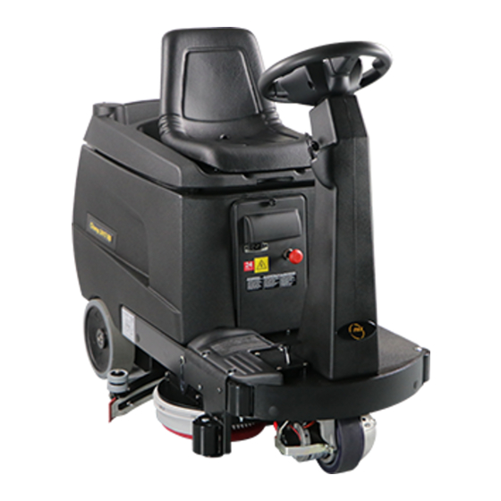
Detergent solution (or washing water) level indi- cator. Front, traction and steering wheel with electro- magnetic brake. Rear wheels. Disc brushes, or pad holder discs (CHAMP 2417 RB with disc brush base) Battery connector. Squeegee. 10. Brush(es) base. 11. Detergent solution (or washing water) tank. -
Page 10: Steering Wheel With Control Panel And Controls
Steering wheel with control and command panel Control and command panel Single brush unlocking pushbutton (available on single disc brush versions only) Display, showing: • 3a = “Ready” (the machine is ready), or “Sit Down” (sit in the seat) • 3b = Total working hours •... -
Page 11: Safety Functions
Safety functions The machine is equipped with the safety functions de- scribed as follows. Electromagnetic brake Electromagnetic brake (A) is integrated in the front wheel traction system and keeps the machine braked when in OFF mode or when it is ON but stationary. Key (A1) locks/releases the brake. -
Page 12: Technical Features
TECHNICAL FEATURES CHAMP 2417 RB Description (Disc brush base) Voltage Cleaning width 24 in/610 mm (2x 12 in/305mm discs) Drying width 30.3 in/770 mm Vacuum 46 in/1168 mm H2O Detergent solution (or washing water) tank capacity 17 gal/65 L Disc brush revolutions... -
Page 13: Accessories And Components (Upon Request)
ACCESSORIES AND COMPONENTS (UPON REQUEST) • Disc brushes (See list below and “Choosing the disc brush type” chapter). • Driver (A) and abrasive disc (B) (See the “Choosing the abrasive disc type” chapter). • Squeegee rubbers in materials other than standard ones (See the “Choosing the type of squeegee rubbers” chapter). -
Page 14: Wiring Diagram 1/2
WIRING DIAGRAM 1/2 ROSA PINK NERO/BLACK NERO/BLACK NERO/BLACK ROSSO/RED CIANO/CYANO BLU/BLUE CIANO/CYANO BLU/BLUE NERO/BLACK NERO/BLACK BLU/BLUE ROSA/PINK NERO/BLACK ROSSO/RED NERO/BLACK BIANCO/WHITE MARRONE/BROWN MARRONE/BROWN BLU/BLUE BLU/BLUE NERO/BLACK BLUE/BLACK NERO/BLACK ROSSO/RED NERO/BLACK ROSSO/RED ROSSO/RED NERO/BLACK ROSSO/RED NERO/BLACK... -
Page 15: Wiring Diagram
WIRING DIAGRAM 2/2 Description of electrical components 7CF00050 Electronic control functions X3 Keyboard connector X2 Functions connector X1 Functions connector X11 Fuse 3A X6 Accelerator pedal X26 Keyboard display 7CFI0010 X8 Battery charger X4 Recovery tank fl oat 10. X6 Water pump 11. -
Page 16: (Codes) Alarm Display
(CODES) ALARM DISPLAY All active alarms on the machine are displayed on the control panel. Alarms may refer to the function unit, the drive unit and the machine general services. Listed below are alarm summary tables complete with any relevant instructions/solutions. “FUNCTION”... -
Page 17: Pushing/Towing The Machine
PUSHING/TOWING THE MACHINE When the drive unit cannot be used (no batteries, fl at batteries, faults, etc.), the electromagnetic brake must be re- leased as follows to push/tow the machine: • Turn lever (A1) “CLOCKWISE” as shown in the fi gure. Never exceed a speed of 3 Km/h during manual pushing/towing. -
Page 18: Batteries
BATTERIES Checking/installing the batteries on a new machine Caution! The machines are predisposed for LEAD-ACID batteries. To charge the batteries, see “Charging the batteries “ section , page 37. ATTENTION! This machine electrical components may become severely damaged if the batteries are not installed and con- nected properly. -
Page 19: Changing The Set Parameters Of The Charging Curve With Battery Charger On Board
(Voltage) > OFF 1 (curve for IUIa GEL EXIDE batteries) 2 (curve for IUoU AGM batteries) Use with NSS #7696501 AGM battery > ON 3 (curve for IUIa Lead-Acid “Wet” batteries) Use with NSS #6393651 battery 4 (curve for IUIUo AGM DISCOVER batteries ) -
Page 20: Recharging Of The Batteries
PRELIMINARY OPERATIONS BEFORE STARTING THE MACHINE ATTENTION! Before starting the machine, always check for any foreign bodies between the brush base (A) and the machine, or between the squeegee (B) and the machine, that may prevent the brushes base and the squeegee from lift- ing. -
Page 21: Brushes
You can clean more quickly with the proper brush; fur- thermore, the increase in productivity may result in sub- stantial cost savings. WARNING! A less than optimal selection could damage the fl oor surfaces. If in doubt, contact the NSS representative. -
Page 22: Abrasive Disc Drivers
WARNING! A less than optimal selection could damage the fl oor sur- face. If in doubt, contact the NSS representative. Replacing the protection rubbers on the brush base-plate Remove plates (3) to replace the rubbers (4) on the right- and... -
Page 23: Squeegee
SQUEEGEE Proceed as follows to assemble/disassemble the squeegee (A) on the machine: ATTENTION! Before activating the ignition key (B), always check for any foreign bodies between the squeegee (A) and the machine, as they may obstruct the squeegee lifting. Disassembling/Assembling the squeegee •... -
Page 24: Tanks
TANKS Checking the recovery water tank Lift the cover (A) using its grip (B) and check that the recovery water tank (C) is empty, otherwise empty it as described in the specifi c “Emptying the tanks” section. Filling the detergent solution tank with water (or washing water) The tank can be fi lled in one of the following ways, depending on the inlet version fi tted on the machine. -
Page 25: Starting And Stopping The Machine
If the ignition key (B) is turned and the operator is not sitting on the seat, the “SIT DOWN” caption appears on the dis- play (D) and no machine functions are available. When the display shows indications other than those described, an intervention is required from the NSS Service Centre. •... -
Page 26: Stopping The Machine
Stopping the machine • Release the pedal (G). • Press button (L) or (M) or (N) “page 25”. to deactivate and lift the relevant functions enabled. Vacuum stops a few seconds after the relevant button is pressed in order to drain all water in the tube. •... -
Page 27: Emptying The Tanks
EMPTYING THE TANKS Emptying the recovery water tank • Move the machine to the recovery water disposal area, in compliance with the emission standards in force. • Rotate the machine ignition key to “0” and remove it. • Disengage the tube (A) from its seat and lift it above the upper edge (B) of the tank until its zone (C) is free from water, then keep it in this position and unscrew the cap (D). -
Page 28: Emptying The Detergent Solution (Or Washing Water) Tank
Emptying the 5-Litre detergent tank (UPON REQUEST - DETERSAVER) To empty the tank (H), proceed as follows: • Remove the tube (L). • Remove the elastic strap (N). • Remove the tank (H) from its support (I). • Open the cap (M) and empty the tank in the area designed for this purpose. -
Page 29: After Using The Machine
AFTER USING THE MACHINE The following operations must be carried out after using the machine at the end of work. • Remove and clean the brushes or abrasive discs, following the procedure described in the “Maintenance - Cleaning the disc brushes” chapter. •... -
Page 30: First Period Of Use
Checking the suction fi lter. √ (2) Replacing the disc brushes or the abrasive √ (2) discs (1) : and after the fi rst 8 hours of operation. (2) : maintenance to be carried out by an authorised NSS Service Centre. -
Page 31: Checking The Machine Operating Hours
Checking the machine operating hours • Sit on the machine seat. • Rotate the ignition key (A) to “I”, then wait a few seconds until the machine “READY” caption (C) appears on the display (B). • The area (D) displays the number of machine operating hours. •... -
Page 32: Checking The Squeegee Rubbers
Checking the squeegee rubbers • Remove and clean the squeegee, following the procedure described in the specifi c section. • Check that front rubber rear rubber tact have cuts tears, otherwise replace them described below. Also check that the front edge (C) of the rear rubber (B) is not worn out, otherwise detach the rubber and reverse it, moving one of the other three edges (if still intact) to the front edge (C) position. -
Page 33: Adjusting The Squeegee
Adjusting the squeegee The squeegee must be properly adjusted in order to ensure a perfect drying of the fl oor. The scrubber drier uses a “BENT” squeegee as shown in the picture. The feature of this type of squeegee is a good water drain to the suction hose, although it is sensitive to the parallel inclination to the ground. -
Page 34: Cleaning The Recovery Tank
Cleaning the recovery tank • Move the machine to the recovery water disposal area, in compliance with the emission standards in force. • Rotate the machine ignition key to “0” and remove it. • If there is recovery water in the tank, empty it (see procedure in the “Emptying the recovery tank” section). •... -
Page 35: Cleaning The Suction Fi Lter
Cleaning the suction fi lter • Remove the vacuum motor (see procedure in the specifi c section). • Remove the suction fi lter (A) from the mount (B). • Clean the suction fi lter with a brush and compressed air (max. 5 Bar). Replace the fi lter if worn out. ATTENTION! Adequately protect body parts (eyes, hair, hands, etc.) when cleaning with compressed air or water guns. -
Page 36: Opening/Closing The Batteries Holder Case And Disconnecting The Battery Connector
Opening/Closing the battery holder case and disconnecting the battery connector Proceed as follows to open the case and disconnect the connector: • Rotate the ignition key to “0” and remove it. • Lift the lever (A) to unlock the battery compartment door (B) and use the handle to open it (C). •... -
Page 37: Charging The Batteries
Charging the batteries Use the battery charger 1 (page 18) when the battery is discharged (see control panel display 3, (page 10). Proceed as belows: READ CAREFULLY THE OPERATIONS MANUAL OF THE BATTERY CHARGER. WARNING! Keeping the batteries charged makes their life last longer. WARNING! When the batteries are fl at, make sure they do not remain in this condition for long as this would shorten their life. -
Page 38: Checking/Replacing The Fuses
Checking/Replacing the fuses ATTENTION! Before replacing the fuses contact the authorised service centre. DO NOT replace fuses with diff erent amperage. • Open the door of the battery compartment, pull out the battery holder case and disconnect the batteries. (see section”... -
Page 39: Disassembling/Assembling The Vacuum Motor
Disassembling/assembling the vacuum motor Proceed as follows to disassemble the vacuum motor: • If available, place the machine on a raised platform, otherwise place it on a level fl oor. • Using the machine controls, lower the brush and the squeegee, then turn the ignition key to “0” and remove it. •... -
Page 40: Troubleshooting
The disc brushes or the abrasive discs Replace the disc brushes or the abra- touch the fl oor: are not cleaning. sive discs. Check the left- and right-hand side pins (E page 33) For further information, contact the NSS Service Centres. -
Page 41: Scrapping
• Batteries • Disc brushes or abrasive discs. • Hoses and plastic parts. • Electrical and electronic parts (*). (*): Refer to the NSS area offi ce for scrapping electrical and electronic parts in particular. - Page 42 ÍNDICE PÁGINA INTRODUCCIÓN • Objeto y contenido del manual • Destinatarios • Conservación del manual • Declaración de conformidad • Datos de identifi cación • Otros manuales de referencia • Repuestos y mantenimiento • Modifi caciones y mejoras • Capacidades operativas •...
- Page 43 ÍNDICE PÁGINA DEPÓSITOS • Control del depósito del agua de recuperación • Llenado de agua del depósito de la solución detergente (o agua de lavado) • Boca en la versión básica • Boca en la versión con kit de llenado (OPCIONAL) •...
-
Page 44: Introducción
Este manual está dirigido tanto al operador como a los técnicos cualifi cados del mantenimiento de la máquina. Los operadores no deben realizar operaciones reservadas a los técnicos cualifi cados. NSS declina toda responsabili- dad por daños derivados del incumplimiento de esta prohibición. -
Page 45: Otros Manuales De Referencia
Para más información sobre el uso, el mantenimiento y la reparación, contacte con el personal cualifi cado o directa- mente con los centros de asistencia NSS. Utilice siempre repuestos y accesorios originales. Contacte con NSS para la asistencia o para solicitar repuestos y accesorios, especifi cando siempre el modelo y el nú- mero de matrícula. -
Page 46: Símbolos Utilizados
Símbolos utilizados ¡PELIGRO! Indica un peligro con riesgo, incluso mortal, para el operador. ¡CUIDADO! Indica un riesgo potencial de accidente para las personas y de daños en objetos. ¡ADVERTENCIA! Indica una advertencia o una nota sobre funciones claves o útiles. Preste la máxima atención a los bloques de texto indicados con este símbolo. - Page 47 • No utilice la máquina para fi nes diferentes de los indicados en este manual. Utilice solo accesorios recomendados por NSS. • Adopte las precauciones oportunas para que el cabello, las joyas, las partes sueltas de la ropa, etc. no queden en- ganchadas en las partes móviles de la máquina.
-
Page 48: Descripción De La Máquina
Indicador de nivel de la solución detergente (o agua de lavado). Rueda delantera, de tracción y de dirección, con freno electromagnético. Ruedas traseras. Cepillos de disco, o disco portafi eltro (CHAMP 2417 RB con base para cepillos de disco) Conector de baterías. Boquilla de secado. 10. Base cepillo/os. -
Page 49: Volante Con Panel De Control Y Mandos
Volante con panel de control y mandos Panel de control y mandos Pulsador de desbloqueo monocepillo (solo para versiones equipadas con un cepillo o disco) Pantalla, que indica: • 3a = “Ready”: máquina lista, o bien “Sit Down” (sentarse en el asiento) •... -
Page 50: Funciones De Seguridad
Funciones de seguridad La máquina está equipada con las funciones de seguri- dad que se describen a continuación. Freno electromagnético El freno electromagnético (A) está implementado en el sistema de tracción de la rueda delantera y mantiene frenada la máquina cuando está apagada y cuando está encendida pero parada. -
Page 51: Características Técnicas
CARACTERÍSTICAS TÉCNICAS CHAMP 2417 RB Descripción (Base de los cepillos de disco) Tensión 24 V Ancho de lavado 24 in/610 mm (2x 12 in/305mm discos) Ancho de secado 30.3 in/770 mm Aspiración 46 in/1168 mm H2O Capacidad del depósito de la solución detergente (o del agua de lavado) -
Page 52: Accesorios Y Componentes Opcionales
ACCESORIOS Y COMPONENTES OPCIONALES • Cepillos de disco (Consulte lista abajo y “Elección del tipo de cepillos de disco”). • Eje impulsor (A) y disco abrasivo (B) (Consulte “Elección del tipo de disco abrasivo”). • Gomas de la boquilla de secado de materiales diferentes de las estándares (Consulte “Elección del tipo de go- mas de la boquilla de secado”). -
Page 53: Esquema Eléctrico 1/2
ESQUEMA ELÉCTRICO 1/2 ROSA PINK NERO/BLACK NERO/BLACK NERO/BLACK ROSSO/RED CIANO/CYANO BLU/BLUE CIANO/CYANO BLU/BLUE NERO/BLACK NERO/BLACK BLU/BLUE ROSA/PINK NERO/BLACK ROSSO/RED NERO/BLACK BIANCO/WHITE MARRONE/BROWN MARRONE/BROWN BLU/BLUE BLU/BLUE NERO/BLACK BLUE/BLACK NERO/BLACK ROSSO/RED NERO/BLACK ROSSO/RED ROSSO/RED NERO/BLACK ROSSO/RED NERO/BLACK... - Page 54 ESQUEMA ELÉCTRICO 2/2 Descripción de los componentes eléctricos 7CF00050 Tarjeta de funciones X3 Conector de del tablero X2 Conector funciones X1 Conector funciones X11 Fusible 3A X6 Pedal de marcha X26 Tablero 7CFI0010 X8 Cargador de baterías X4 Flotador del depósito agua sucia 10.
-
Page 55: (Códigos) Visualización De Alarmas
(CÓDIGOS) VISUALIZACIÓN DE ALARMAS Las alarmas activas en la máquina se visualizan en la pantalla del panel de mandos. Las alarmas pueden estar asociadas con la parte de las funciones, la parte de la tracción y los servicios generales de la máquina. -
Page 56: Empuje/Arrastre De La Máquina
EMPUJE/ARRASTRE DE LA MÁQUINA Cuando es imposible utilizar la tracción (en caso de falta de baterías, baterías descargadas, averías, etc.) para mover la máquina por empuje/arrastre, es necesario desbloquear el freno electromagnético siguiendo los pasos que se describen a continuación: •... -
Page 57: Baterías
BATERÍAS Control/Instalación de las baterías en una máquina nueva ¡CUIDADO! Las máquinas están confi guradas para baterías de Plomo-Ácido. Para cargar las baterías, consulte la sección “Carga de las baterías”, página 76. ¡CUIDADO! Los componentes eléctricos de esta máquina pueden sufrir daños graves si las baterías no se instalan y conectan correc- tamente. -
Page 58: Cambio De Los Parámetros De La Curva De Carga Con Cargador De Baterìa A Bordo
1 (curva IUIa para baterías de GEL EXIDE) 2 (curva IUoU para baterías AGM) aplicar con baterìa “AGM” NSS #7696501 > ON 3 (curva IUIa para baterías de PLOMO-ÁCIDO “con líquido”) aplicar con baterìa NSS #6393651 4 (curva IUIUo para baterías AGM DISCOVER ) -
Page 59: Operaciones Preliminares Antes De La Puesta En Marcha De La Máquina
OPERACIONES PRELIMINARES ANTES DE LA PUESTA EN MARCHA DE LA MÁQUINA ¡CUIDADO! Cada vez que encienda la máquina, controle que no haya cuerpos extraños entre la base del cepillo (A) y la máquina, o bien entre la boquilla de secado (B) y la máquina, que puedan obstaculizar la elevación de la base de los cepillos y de la boquilla de secado. -
Page 60: Cepillos
¡ADVERTENCIA! Una mala elección podría dañar las superfi cies del suelo. En caso de dudas, póngase en contacto con el representante NSS. -
Page 61: Ejes Impulsores Para Discos Abrasivos
¡ADVERTENCIA! Una elección no óptima podría dañar las superfi cies del suelo. En caso de dudas, póngase en contacto con el representante NSS. Sustitución de las gomas de protección en la base de los cepillos Para sustituir las gomas 4 en el lado derecho e izquierdo... -
Page 62: Boquilla De Secado
BOQUILLA DE SECADO Para montar y desmontar la boquilla de secado (A) en la máquina, siga los pasos descritos a continuación: ¡CUIDADO! Antes de accionar la llave de encendido (B), controle siempre que no haya cuerpos extraños entre la boquilla de secado (A) y la máquina, ya que podrían obstaculizar la elevación de la boquilla de secado. -
Page 63: Depósitos
DEPÓSITOS Control del depósito del agua de recuperación Levante la tapa (A) mediante su asa (B) y controle que el depósi- to del agua de recuperación (C) esté vacío; de no ser así hay que vaciarlo siguiendo los pasos indicados en el apartado específi co “Vaciado de los depósitos”. -
Page 64: Puesta En Marcha Y Parada De La Máquina
DOWN” (siéntese) y ninguna función de la máquina está disponible. Cuando la pantalla muestra indicaciones diferentes de las descritas, hay que solicitar la intervención del Servicio de asistencia de NSS. • Controle el estado de carga de las baterías mirando la indicación porcentual (E) y la correspondiente indicación gráfi ca (F). -
Page 65: Parada De La Máquina
Parada de la máquina • Suelte el pedal (G). • Presione los pulsadores (L), (M) o (N) “pág.64” para desactivar y levantar las funciones activas. La aspiración se interrumpe durante algunos segundos tras accionar el pulsador correspondiente, para aspirar toda el agua presente en la tubería. •... -
Page 66: Vaciado De Los Depósitos
VACIADO DE LOS DEPÓSITOS Vaciado del depósito del agua de recuperación • Desplace la máquina hasta la zona destinada a la eliminación del agua de recuperación, de acuerdo con las normas vigentes contra la contaminación. • Gire la llave de encendido de la máquina en “0” y retírela. •... -
Page 67: Vaciado Del Tanque De Detergente De 5 Litros (Detersaver - Opcional)
Vaciado del tanque de detergente 5 litros (DETERSAVER - OPCIONAL) Para el vaciado del tanque 1, siga el procedimiento descrito a continuación: • Extraiga el tubo (L). • Quite la correa elástica (N). • Quite el tanque (H) del soporte (I). •... -
Page 68: Tras El Uso De La Máquina
TRAS EL USO DE LA MÁQUINA Al fi nal del trabajo, después del uso de la máquina es necesario llevar a cabo las operaciones descritas a continuación. • Quite y limpie los cepillos o los discos abrasivos, siguiendo las indicaciones descritas en el capítulo “Manteni- miento - Limpieza de los cepillos de disco”. -
Page 69: Primera Temporada De Uso
√ (1) (2) Control del fi ltro de aspiración √ (2) Sustitución de los cepillos de disco o discos √ (2) abrasivos. (1): y tras las primeras 8 horas de trabajo. (2): del mantenimiento se encarga un Centro de asistencia autorizado NSS. -
Page 70: Control De Las Horas De Trabajo De La Máquina
Control de las horas de trabajo de la máquina • Siéntese en el asiento de la máquina. • Gire la llave de encendido (A) en “I”; después, espere unos segundos hasta que en la pantalla (B) aparezca el mensaje (C) “Ready” de máquina lista. •... -
Page 71: Control De Las Gomas De La Boquilla De Secado
Control de las gomas de la boquilla de secado • Desmonte y limpie la boquilla de secado, siguiendo las indicaciones descritas en el apartado específi co. • Controle goma delantera trasera sean intactas, cor- tes o abrasiones; de ser el caso, sustitúyalas, tal y como se describe a continuación. Controle también que el canto delantero (C) de la goma trasera (B) no sea desgastado;... -
Page 72: Regulación De La Boquilla De Secado
Regulación de la boquilla de secado Una exacta regulación de la boquilla de secado es muy importante a la hora de lograr un secado perfecto del suelo. La fregadora emplea una boquilla de secado de tipo “CURVO”, como se muestra en la foto. La característica de este tipo de la boquilla de secado es una buena recogida de agua hacia el tubo de aspiración, pero es sensible al hecho de ser paralelo con el suelo. -
Page 73: Limpieza Del Depósito De Recuperación
Limpieza del depósito de recuperación • Desplace la máquina hasta la zona destinada a la eliminación del agua de recuperación, de acuerdo con las normas vigentes contra la contaminación. • Gire la llave de encendido de la máquina en “0” y retírela. •... -
Page 74: Limpieza Del Fi Ltro De Aspiración
Limpieza del fi ltro de aspiración • Extraiga el motor de aspiración (consulte el procedimiento en el apartado específi co). • Extraiga el fi ltro de aspiración (A) del soporte (B). • Limpie el fi ltro de aspiración con un pincel y aire comprimido (máx. 5 Bares). Si el fi ltro está deteriorado, susti- túyalo. -
Page 75: Apertura/Cierre De La Caja Porta Baterías Y Desconexión Del Conector De Baterías
Apertura/Cierre de la caja porta baterías y desconexión del conector de baterías Para abrir la caja y desconectar el conector, hay que seguir los pasos que se indican a continuación: • Girar la llave de encendido en “0” y extráigala. •... -
Page 76: Carga De Las Baterías
Carga de las baterías Cuando la batería está descargada (ver panel de control y mandos, pantalla 3 (pág. 49) recargarla por medio del car- gador 1 (pag.57). Proceder de la siguiente manera: LEER CUIDADOSAMENTE EL MANUAL DE USO DEL CARAGADOR ADQUIRIDO. ¡ADVERTENCIA! Mantener las baterías cargadas prolonga su vida útil. -
Page 77: Control/Sustitución De Los Fusibles
Control/Sustitución de los fusibles ¡ATENCIÓN! Antes de sustituir los fusibles, contacte con un técnico cualifi cado del servicio de asistencia. NO reemplace los fusibles con fusibles de diferente amperaje. • Abra la puerta de la caja de las baterías, tire de la bandeja y desconecte las baterías (consulte la sección “Aper- tura/Cierre de la caja porta baterías y desconexión del conector de baterías”) •... -
Page 78: Desmontaje/Montaje Del Motor De Aspiración
Desmontaje/montaje del motor de aspiración Para desmontar el motor de aspiración, siga los pasos que se describen a continuación: • Coloque la máquina en una plataforma de elevación si está disponible, si no en un suelo plano. • Interviniendo en los mandos de la máquina, baje el cepillo y la boquilla de secado, luego gire la llave de encen- dido hasta la posición “0”... -
Page 79: Localización De Averías
Los cepillos de disco o los discos Sustituya los cepillos o los discos tocan el suelo; controle: abrasivos no limpian. abrasivos. Los pernos laterales izquierdo y dere- cho (E pág. 72) Para más información, contacte con los Centros de Asistencia NSS. -
Page 80: Desguace
Baterías • Cepillos de disco o discos abrasivos. • Tubos y partes de material plástico. • Partes eléctricas y electrónicas (*). (*): En particular para el desguace de las partes eléctricas y electrónicas, contacte con la Sede de NSS local.
Need help?
Do you have a question about the CHAMP 2417 RB and is the answer not in the manual?
Questions and answers
How do I unlock the speed? The speed only goes up to one and two.
To adjust the speed settings on the NSS CHAMP 2417 RB, press the machine maximum speed adjustment button. Each press increases the speed. The instantaneous speed is shown by an indicator light.
This answer is automatically generated
What to do when water level is blinking al 11 function
When the water level is blinking on the NSS CHAMP 2417 RB at function 11 (AL_11), it means the water tank is full. You should check the water tank level.
This answer is automatically generated