Table of Contents
Advertisement
Quick Links
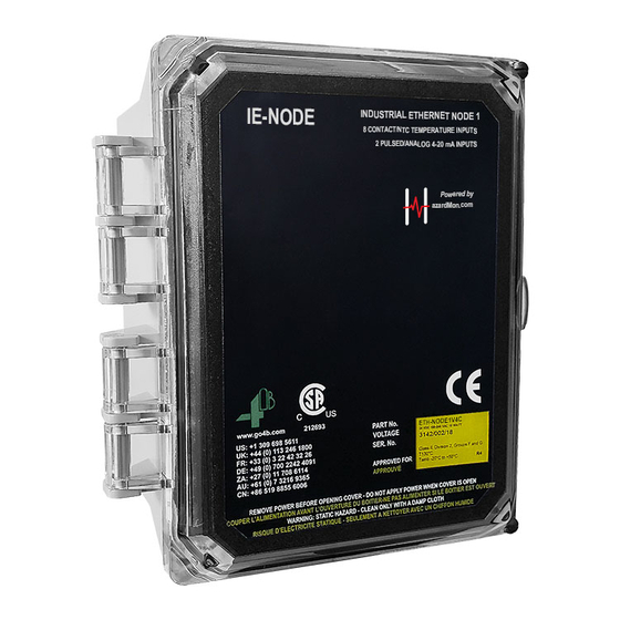
IE-NODE
INDUSTRIAL ETHERNET NODE 1
8 CONTACT/NTC TEMPERATURE INPUTS &
2 PULSED/4-20 mA INPUTS
COMMUNICATION PROTOCOLS -
PROFINET, ETHERNET/IP & MODBUS TCP/IP
INSTALLATION INSTRUCTIONS
OPERATION MANUAL
Part No.'s - ETH-NODE1V46CAI, ETH-NODE1V4CAI
Hardware Version R4 - Software Version 4.1.X - Ethernet 00.02.XX
www.go4b.com
Advertisement
Table of Contents

Subscribe to Our Youtube Channel
Related Manuals for 4B IE-NODE Series

Summary of Contents for 4B IE-NODE Series
- Page 1 IE-NODE INDUSTRIAL ETHERNET NODE 1 8 CONTACT/NTC TEMPERATURE INPUTS & 2 PULSED/4-20 mA INPUTS COMMUNICATION PROTOCOLS - PROFINET, ETHERNET/IP & MODBUS TCP/IP INSTALLATION INSTRUCTIONS OPERATION MANUAL Part No.’s - ETH-NODE1V46CAI, ETH-NODE1V4CAI Hardware Version R4 - Software Version 4.1.X - Ethernet 00.02.XX www.go4b.com...
- Page 2 DANGER Exposed buckets and moving parts will cause severe injury or death. Lockout power before removing cover or inspection door. WARNING Moving parts can crush and cut. Lockout power before removing guard or servicing. Do NOT operate with guard removed...
-
Page 3: Table Of Contents
TABLE OF CONTENTS 1. CUSTOMER SAFETY RESPONSIBILITIES Page 4 - 5 2. PRODUCT OVERVIEW Page 6 3. SPECIFICATIONS Page 6 4. APPROVALS Page 7 5. DIMENSIONS Page 8 6. INSTALLATION Page 8 7. SENSOR PLACEMENT DIAGRAMS Page 9 8. ELECTRICAL CONNECTION Page 10 9. -
Page 4: Customer Safety Responsibilities
The proper installation and maintenance of all our products is the responsibility of the user unless you have asked 4B to perform these tasks. B. All installation and wiring must be in accordance with Local and National Electrical Codes and other standards applicable to your industry. - Page 5 3. SELECT A QUALIFIED AND COMPETENT INSTALLER Correct installation of the product is important for safety and performance. If you have not asked 4B to perform the installation of the unit on your behalf, it is critical for the safety of your operation and those who may perform work on your operation that you select a qualified and competent electrical installer to undertake the installation.
-
Page 6: Product Overview
(e.g. PLC). The unit is equipped with an RJ45 Ethernet socket and supports PROFINET, EtherNet/ IP and Modbus TCP/IP protocols for easy integration with Siemens, Allen-Bradley Rockwell, Modicon and other PLC’s or automation devices. The IE-NODE can be used with the following 4B sensors: Temperature (Bearing & Surface) - • ADB Series (NTC Type) •... -
Page 7: Approvals
4. APPROVALS ETH-NODE1V46CAI Approvals Information Class II, Division 2, Groups F and G T130°C Tamb: -20°C to +50°C Baseefa11ATEX 0033X ATEX Ex II 3D Ex tc IIIC T125°Dc IP66 TAMB -20°C to +45°C IECEx BAS11.0018X IECEx Ex tc IIIC T125°Dc IP66 TAMB -20°C to +45°C ETH-NODE1V4CAI Approvals Information Class II, Division 2, Groups F and G T130°C... -
Page 8: Dimensions
5. DIMENSIONS 6. INSTALLATION The IE-NODE should be installed in an area with network Ethernet access. ENCLOSURE INSTALLATION - 1. Use the correct cable, glands and sealing arrangement in accordance with all installation codes. 2. Where other certified components are used as part of the assembly or installation procedure, the user must take in to account any limitations which might be listed on the relevant certificates. -
Page 9: Sensor Placement Diagrams
7. SENSOR PLACEMENT DIAGRAMS TYPICAL SENSOR PLACEMENT FOR BUCKET ELEVATORS & ENCLOSED BELT CONVEYORS SPEED MONITORING Qty 1 - One sensor located on either side of the tail or boot shaft. BEARING TEMPERATURE Qty. 4 - One sensor for the bearings at each end of the drive and tail or head and boot shafts. -
Page 10: Electrical Connection
Additional wire used during the installation must have a temperature rating of 158° F (70° C) or above, and be at least 24 AWG. 4B recommends using shielded cable to reduce electromagnetic interference (EMI) to maintain signal integrity. Never run sensor cables in the same conduit as three phase motor cables. - Page 11 WARNING The unit should ONLY be powered with either a main supply (ETH-NODE1V46CAI model) OR a 24 VDC (ETH-NODE1V4CAI) NOT BOTH (see specifications). RJ45 Ethernet DIP Switches (SW2) FIELD WIRING CONNECTIONS 01 - 0 VDC 02 - T#1 Temp/Belt Align Power Supply 03 - T#2 Temp/Belt Align Location...
-
Page 12: Wiring Diagrams
9. WIRING DIAGRAMS 9.1 SUPPLY VOLTAGE WIRING (120 TO 240 VAC) Connection Fuse Ground 9.2 SUPPLY VOLTAGE WIRING (24 VDC) Connection Fuse 24 VDC Ground PAGE 12... -
Page 13: Wiring Block Diagram For Elevator & Conveyor
9.3 WIRING BLOCK DIAGRAM FOR BUCKET ELEVATOR & BELT CONVEYOR - Hot Bearing Hot Bearing Sensor Sensor Junction TOP LEFT TOP RIGHT Alignment Alignment HEAD / DRIVE Top Left Top Right Denotes shielded INDUSTRIAL cable. Shield to IE-NODE be grounded at one end only. -
Page 14: Standard System Sensor Wiring Diagram A
9.4 STANDARD SENSOR WIRING DIAGRAM A: - NTC SENSORS (BEARING TEMP), TOUCHSWITCHES (ALIGNMENT) & P800 (SPEED) 0 VDC Black Brown RIGHT Bearing Top (Head) LEFT Black Brown +24 VDC (Fuse F1) 0 VDC Black Brown RIGHT Bearing Bottom (Tail) LEFT Black +24 VDC (Fuse F2) Brown... -
Page 15: Standard System Sensor Wiring Diagram B
9.5 STANDARD SENSOR WIRING DIAGRAM B: - NTC SENSORS (BEARING TEMP), RUB BLOCKS (ALIGNMENT) & MILLI-SPEED (SPEED) 0 VDC Black Brown RIGHT Bearing Top (Head) LEFT Black Brown +24 VDC (Fuse F1) 0 VDC Black Brown RIGHT Bearing Bottom (Tail) LEFT Black Brown... -
Page 16: Individual Bearing Sensor Wiring Diagrams
9.6 INDIVIDUAL BEARING SENSOR WIRING DIAGRAMS: 0 VDC Black Brown +24 VDC 4-20 mA 0 VDC Black Brown +24 VDC 9.7 INDIVIDUAL BELT ALIGNMENT SENSOR WIRING DIAGRAMS: Touchswitch 0 VDC Black Orange White Blue Green +24 VDC NTC Rub Block 0 VDC Black Brown... -
Page 17: Individual Speed Sensor Wiring Diagrams
9.8 INDIVIDUAL SPEED SENSOR WIRING DIAGRAMS: P800 0 VDC White Blue Speed Brown Black +24 VDC M800 Elite 0 VDC Brown Blue Speed Pink White +24 VDC NOTE The M800 Elite is an 8 wire switch. The diagram above illustrates the IE-NODE connection only, the remaining wires are for the alarm and shutdown relays. -
Page 18: Ie-Node Operation
10. IE-NODE OPERATION The Industrial Ethernet Node is designed to sample data from several sensors and provide this data to remote users or PLC’s on request. It is only a reporting system, and does not control any other system or device. 10.1 STARTUP OPERATION - After all sensor and power connections have been made, locate the POWER and HB (Heart Beat) LED’s on the IE-NODE’s control board (See Image 1). -
Page 19: Dip Switches (Sw2)
10.3 DIP SWITCHES (SW2) - The IE-NODE has a set of eight DIP switches to change settings (Image 3). Each switch setting is described in the table below. If a switch setting is changed, the unit must be restarted for the change to take effect. -
Page 20: Internal Temperature Sensor
10.10 INTERNAL TEMPERATURE SENSOR - In addition to the 10 sensor inputs, the IE-NODE is fitted with an internal NTC temperature sensor. This device is mounted to the IE-NODE PCB and will therefore provide the temperature of the electronics. If an IE-NODE is mounted in the field, it could be used to approximate the local ambient temperature, but will report temperatures approximately 10°F (5°C) higher than local ambient. -
Page 21: Ie-Node Network Configurator Software
It allows for easy identification for each unit on the network, and allows you to change network settings as needed. The software does not ship with the unit, it is available as a free download from 4B’s website (see the IE- NODE product page). - Page 22 A “Network Configurator” will launch and rescan the network - Image 7 - Network Configurator Menu If nothing is found, try updating your computer’s network settings to the same IP address range as the IE-NODE and select “Refresh List”. To change the network settings of an IE-NODE, highlight it from the device list and select “Network Settings”...
- Page 23 If you prefer to use the built-in web server on the IE-Node, you can select “Update IE-NODE Configuration Settings” icon from the main menu, or simply enter the node’s IP address into a web browser. Enter the user name “root” followed by the password “BBBB” then select “OK”. Once logged in, you will be taken to the home page on the web server.
- Page 24 ON (Right) position. Otherwise, the rotary switch will override the address in memory. Unless instructed by 4B, do not use “Update IE-NODE Main/Auxiliary Firmware” or “Update DIGI Module via FTP” from the IE-NODE’s Configurator Menu (Image 6) as these options are used for firmware updates.
-
Page 25: Troubleshooting Guide
14. TROUBLESHOOTING GUIDE CONDITION SOLUTION 1. Check that power is applied to the unit on appropriate terminals (21 - 24). Power LED is Off 2. Check that the mains input fuse F6 is not damaged. 3. Check that the internal circuitry fuse F5 is not damaged. 1. - Page 26 END USER NOTES PAGE 26...
-
Page 27: Product Warranty
4B France herein after referred to as 4B to the original purchaser against defects in workmanship or materials under normal use for one (1) year after date of purchase from 4B. Any product determined by 4B at its sole discretion to be defective in material or workmanship and returned to a 4B branch or authorized service location, as 4B designates, shipping costs prepaid, will be, as the exclusive remedy, repaired or replaced at 4B’s option. - Page 28 Fax: +33 3 22 42 37 33 Tel: +27 11 708 6114 Tel: +61 7 3216 9365 Changzhou 213164, Jiangsu Province, Fax: +27 11 708 1654 Fax: +61 7 3219 5837 China Tel: +86 519-88556006 www.go4b.com Copyright © 2019 4B Group - All Rights Reserved REV092019...
Need help?
Do you have a question about the IE-NODE Series and is the answer not in the manual?
Questions and answers