Table of Contents
Advertisement
Advertisement
Table of Contents

Related Manuals for Wisi GT 01W Tangram

Summary of Contents for Wisi GT 01W Tangram
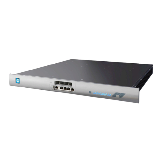
- Page 1 GT 01W Tangram with GT22 Edge-Decoder ( IP to FM ) GT 01 WISI Tangram chassis...
- Page 2 Tangram GT Operating instructions GT22C WISI Tangram FM module Features: The GT22C module is part of the Gigabit Ethernet MPEG-TS Tangram product portfolio. analogue FM- Decoder MPEG decoding Up to 8x FM outputs (SD) Test ports for the output signal...
- Page 3 This page is intended to be empty...
-
Page 4: Table Of Contents
IP / Ethernet Ports Groups (using internal VLAN IDs) ........16 Configuration of Modules.................... 17 3.8.1 Connecting to the Modules:................. 17 3.8.2 Adding additional IP addresses to the modules (optional) ........17 Tangram & SW options ....................18 3.9.1 Connect to WISI portal & activating the Modules:..........18... - Page 5 Version 22.12.2011 0.1- 0.9 Versions for Pre-GT PK , a2b 22.08.2012 Adapted for GT in PP HP,KD 04.09.2012 1.1-1.3 WISI doc. design, Updates 11.09.2012 1.4-1.47 GT11 TDG Updates 06.11.2012 1.48-1.49 Module Updates 03.12.2012 1.50-1.51 TDG Inputs, Updates 01.03.2013 1.52...
-
Page 6: Safety Instructions
Tangram GT Operating instructions 1 Safety instructions 1.1 ESD protection This product contains electrostatic sensitive devices. These devices can be damaged or effectively destroyed by electrostatic discharge (ESD) during unpacking, installation, removal, storage, or shipment if incorrectly handled. Please note that discharge might go unnoticed by a user. -
Page 7: Technical Data / Mechanical Overview
2 Technical data / Mechanical overview 2.1 GT22C Module Front view GT22C module view (RF output 2 not used) For best performance please always terminate the Test-output 1 (z = 75 Ohms). -
Page 8: Installation, Configuration And Maintenance
Operating instructions 3 Installation, configuration and maintenance 3.1 Module installation The GTxx modules are single function modules. The modules are hot-swappable and can be plugged into the chassis from the back. On the front side there are the switch modules plus the power supplies and the removable fan tray behind the panel. The physical Installation of GTxx modules, Power supplies &... - Page 9 Operating instructions This page is intended to be empty - 9 -...
-
Page 10: Tangram Front Ip Ports
Operating instructions 3.2 Tangram Front IP Ports 3.2.1 IP / Ethernet Ports at the Front of Tangram Tangram has up to 9x GigE ports at the front side, 5x RJ-45 100/1000T with GT11 and optionally additional 4x SFP ports with GT12 at the upside position (Slot 8). Tangram with GT11 Switch module (Slot 7) Tangram equipped with GT11 &... -
Page 11: Tangram Rf / Video Modules Slots
Operating instructions 3.3 Tangram RF / Video Modules Slots RF Modules and Ports at the Rear of Tangram 3.3.1 Chassis slots GT01 Tangram has up to 6 module slots on the rear side. Tangram rear view (Example) The numbering on Tangram modules is always from down to up and from left to right, the first lower Module on the left (seen from the back) is the first, second is above. -
Page 12: Configuration Of Tangram
Operating instructions 3.4 Configuration of Tangram 3.4.1 Connecting to the Tangram Web UI (GUI) Connecting with web browser Use a standard web browser on your computer to connect by typing the IP address of the Tangram in the address field. Supported web browsers The Tangram web interface is verified for Firefox version 9 and higher. -
Page 13: Connecting To The Default Management Ip Address
Operating instructions 3.4.2 Connecting to the default Management IP address: The Tangram default IP address on the left front management port is 192.168.1.20 (GT11 SW rel. <0.8.1.5 : 192.168.0.11) To access the Tangram Web- Interface please set the IP address on your PC or Network adaptor to an address in the same address subnet &... -
Page 14: Tangram Gt11 / 12 Switch Modules / Main Control Page
Operating instructions 3.5 Tangram GT11 / 12 Switch modules / Main Control Page 3.5.1 Main Status GT11- Control On the Tangram GT11-Control Status Tab you can monitor overall stats like Alarms, Fans, Power, Temperature, Serial Number and main SW- Version of Tangram . In the left field you can see the GT Modules / Slots identified by the Chassis. -
Page 15: Tangram Gt11 / 12 Internal Switch / Control Tab
Operating instructions 3.6 Tangram GT11 / 12 internal Switch / Control tab 3.6.1 Modules tab On the Tangram GT11 Control Tab you can maintain the modules: In the left field there are the Modules / Slots identified by the Chassis / Switch. 3.6.2 Module Status and Settings You can check and set the Modules on the Modules tab. -
Page 16: Tangram Front Ip Port Groups
Operating instructions 3.7 Tangram Front IP Port Groups 3.7.1 IP / Ethernet Ports Groups (using internal VLAN IDs) There are Port Groups to easily distribute video traffic of above 1 Gbit: GT11/ 12 reserved Groups (VIDs 10 & 16) GT11 MGMT Port 0: Connection to GT switch and module web UI. Internal Management net uses VID=16: internal use reserved. -
Page 17: Configuration Of Modules
IP address in the address field. ) If the address setting is unknown or lost you can recover on the module control port by using the WISI / a2b IP Supporter tool - you can download it from the WISI portal. - 17 -... -
Page 18: Tangram & Sw Options
The Tangram modules GT2x (not the chassis itselve and GT11) must be registered at the WISI portal & activated through a entitlement file when they are shipped with the factory default setup. You can get / download that from WISI Web-Portal: The WISI Tangram portal Portal URL: http://tangramconnect.tv... - Page 19 Description (these fields are intended for your own use, to be able to track and maintain your installed base). The fields for SLA status and SW options are filled out automatically from the information stored in the WISI Unit Data Base. Click the `Register´ button to register the Tangram.
- Page 20 Operating instructions 3.11 Configuring Inputs 3.11.1 Defining / adding inputs Add input 1. Click the INPUTS tab, and Add new input. 2. Type or select the appropriate parameters and settings. 3. Click the SAVE button. Status information After clicking Save, the status of the input will be shown. The status includes information about the interface (tuner etc.), and about services found.
- Page 21 A and B and even more sources (C,D,E …) can be configured on the WISI Tangram integrated switch and afterwards choosen on the Tangram modules via the internal streaming net ( Net A-> VID2 = VLAN ID 2, see 3.7.1).
- Page 22 Operating instructions Alternative Streaming paths – GT21 example redundant Streaming path using VID5= E 3.11.3 Redundant Input Sources Alternative Inputs The Tangram modules searchs for a valid input signal always in the following order: Primary -> Alternative 1 -> Alternative 2 -> Alternative 3 - Search for a valid input signal starts always with the logical input position ´Primary` - GTxx module checks during Latency Time (3sec) the input signal.
- Page 23 Operating instructions This process continues until a valid input signal is detected. The “Linger time” (=waiting period) is the time the Tangram GTxx module waits with a detected signal failure at the current logical input position in order to decide whether action is needed (t >Linger time, then switch to next alternative) or only a brief interruption of signal has appeared at the entrance and no action is needed, to prevent continous input flapping.
- Page 24 Operating instructions 3.12 Configure FM outputs 3.12.1 Add FM output 1. Click the OUTPUTS tab, and choose FM output 1…8. 2. Select the output by clicking on the + 3. Click on EDIT and type or select parameters & settings. 3.12.2 Add more FM outputs Re-iterate the “Add FM output”...
- Page 25 Operating instructions 3.12.3 Configure FM outputs (cont.) - Select the service in the Services drop down list - Enter output frequency and output level - Optional: for RDS signalling, select the PI, PS and PTY sources, and enter the values if using manual settings.
- Page 26 Operating instructions 3.13.1 Service management Click on the SERVICE MANAGEMENT tab to see available inputs and outputs. Service IDs and PIDS of received Input services are shown and can be checked. Service IDs shown in the Module SERVICE MANAGEMENT The INPUTs and their PIDs are shown starting from INPUT 0 to INPUT n, depending on how many Inputs are configured and received.
- Page 27 Operating instructions 3.14 Managing the Tangram modules Under SETTINGS tab - module specific settings are managed: NETWORKING Networking settings for defining and configuring IP interfaces, and for setting the capabilities for the defined IP interfaces. Note: Every Tangram module has an extra IP port on the Tangram back for separate 10/100 Ethernet management (“Control Port”, default IP 192.168.1.20/24), the module internal GigE port is switched through GT11 switch for streaming &...
- Page 28 Operating instructions Managing the Tangram modules 3.14.1 Add and configure Network interfaces 1. Click on NETWORKING in the SETTINGS tab 2. Click Add new interface 3. Type a name for the interface 4. Enter the IPv4 address, the Netmask and the Gateway 5.
- Page 29 Operating instructions Managing the Tangram modules 3.14.2 Setting up DATE AND TIME To sychronize Tangram modules with a time source you can either use NTP protocol through the IP interfaces or Time information delivered by the received MPTS- Streams. 1. Click on DATE AND TIME in the SETTINGS tab 2.
- Page 30 Example of SNMP Network setup MIB, MIB structure and NMS integration: Please ask WISI support or your WISI representative for the most recent MIB- Definition files for Tangram.
- Page 31 Operating instructions Managing the Tangram modules 3.14.4 USER MANAGEMENT Account Management for User authentication & access to the modules The USER MANAGEMENT allows settings of user authentication for the module UI. You can add users, and create passwords for each user: Adding a user and password - Click Add new user, or the green plus - Enter a user name &...
- Page 32 Note: The SW options file will have the format <serial number>.ent. If you need to, you can download the entitlement file from the Tangramconnect.tv portal or please ask your WISI representative • Locate the software options file on your PC, and select it •...
- Page 33 Operating instructions Managing the Tangram module 3.14.7 Module maintenance Module maintenance functions are available within the Maintenance tab: Reboot of the module Some operations, such as upgrading the software, require a reboot to get it active. Click the Reboot button to reboot the unit. During the rebooting process, “Rebooting”...
- Page 34 Operating instructions 3.14.8 Factory reset & Backup / Restore Factory reset The Tangram module can be reset to the same status as when delivered from the factory. Go to the SETTINGS tab, and MAINTENANCE. Before you Click on FACTORY RESET please always do a backup of your last configuration as described below ! It may help you to save time &...
- Page 35 SW options. A warning will be shown if no operation mode is selected. STATUS Uptime (from last reboot), and current module temperature. SERVICE LICENCE AGREEMENT Shows if the Tangram is registered at the WISI portal, and the expiry date of the service level agreement. - 35 -...
- Page 36 Operating instructions 5. GT22 Module LEDs & Alarms 5.1 GT22 master board The GT22 master has 2 status LEDs. LED1 is located between RF1-TP and RF1, LED2 is located between (unused) RF2-TP and RF2. Both LEDs are bi-colour (green and red). Switching on both green and red results in a yellow /orange tone color.
- Page 37 Operating instructions 5.5.2 Status LED indication LED2 Description LED1 No power supply Yellow Yellow Board has power, no software running (e.g. empty flash) Bootloader started or rescue bootloader start complete Bootloader failed to boot into firmware/rescue bootloader, board stopped Red blinking Red blinking Rescue bootloader started Green Red blinking...
- Page 38 6. Support and further information For further information and help, please contact our support organisations: E-mail: support_headend@wisi.de Telephone: +49 (0)7233 / 66-621 User manual and installation guide updates Updates to the user manual and the installation guide are available at the Website www.wisi.de...
- Page 39 Operating instructions 12/12 - 39 -...
Need help?
Do you have a question about the GT 01W Tangram and is the answer not in the manual?
Questions and answers