Table of Contents
Advertisement
Style 9333 & 9335 Retrofit Kit Installation Instructions
Table of Contents
1.
Introduction . . . . . . . . . . . . . . . . . . . . . . . . . . . . . . . . . . . . . . . . . . . . . . . . . . . .
2.
TOOLS REQUIRED . . . . . . . . . . . . . . . . . . . . . . . . . . . . . . . . . . . . . . . . . . . . . . . . 2
3.
PRODUCT RATINGS . . . . . . . . . . . . . . . . . . . . . . . . . . . . . . . . . . . . . . . . . . . . . . . 2
4.
OVERVIEW . . . . . . . . . . . . . . . . . . . . . . . . . . . . . . . . . . . . . . . . . . . . . . . . . . . . . . 2
5.
SYSTEM INSTALLATION . . . . . . . . . . . . . . . . . . . . . . . . . . . . . . . . . . . . . . . . . . .
5.1.
ELECTRICAL INSTALLATION . . . . . . . . . . . . . . . . . . . . . . . . . . . . . . . . . . . . 3
5.2.
MECHANICAL INSTALLATION . . . . . . . . . . . . . . . . . . . . . . . . . . . . . . . . . .
6.
INITIAL SETUP FOR A NEW SYSTEM - MINIMUM SETUP . . . . . . . . . . . . . . . .
6.1.
ASSIGNING A VALVE . . . . . . . . . . . . . . . . . . . . . . . . . . . . . . . . . . . . . . . . .
6.2.
CALIBRATING VALVE POSITION . . . . . . . . . . . . . . . . . . . . . . . . . . . . . . . .
7.
OPERATIONAL FEATURES . . . . . . . . . . . . . . . . . . . . . . . . . . . . . . . . . . . . . . . . .
7.1.
Opening and closing the valve . . . . . . . . . . . . . . . . . . . . . . . . . . . . . . . . .
127639
2
3
3
3
4
4
5
5
Advertisement
Table of Contents

Related Manuals for Akron Brass 9333

Summary of Contents for Akron Brass 9333
- Page 1 Style 9333 & 9335 Retrofit Kit Installation Instructions Table of Contents Introduction ........... .
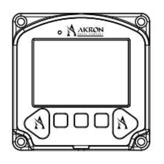
- Page 2 The Style 9333/9335 Navigator Pro controller allows the user to control an Akron Brass electric valve. It is designed to be used with an Akron Brass Swing-Out valve only. The Style 9333/9335 is a display interface only and does not contain the electronics required to drive the valve open and closed.
- Page 3 5.2 MECHANICAL INSTALLATION The 9333/9335 valve controller display will fit the existing panel cutout and mounting holes from the 9303 or 9313/9315 and is attached to the panel using four 10-24 socket-head cap-screws. An installation torque of 6-8 in-lbs should be applied when installing the valve controller display to prevent damage to the enclosure.
- Page 4 6.1 ASSIGNING A VALVE Before controlling a valve, the Style 9333/9335 Navigator Pro must be assigned to that valve. This step tells the display what valve it is controlling. In order for the assignment to take place, the desired valve must be powered and connected to the Navigator Pro controller.
- Page 5 ■ OK button to return to the Valve Setup screen. 7 OPERATIONAL FEATURES The Style 9333/9335 Navigator Pro Controller has been designed to be intuitive and easy to use. Once configured, the operation is simple. Basic operation of the controller is described below.
Need help?
Do you have a question about the 9333 and is the answer not in the manual?
Questions and answers