
Related Manuals for Chino EH3000 Series


Summary of Contents for Chino EH3000 Series
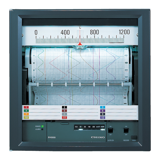
- Page 1 INST.No. INE-866 EH3000 series (DOT-PRINTING TYPE/PEN TYPE) 180 mm ANALOG RECORDER Instruction Manual...
-
Page 3: Table Of Contents
-CONTENTS- 6.4 Recording Operation (AUTO CH/ ❐INTRODUCTION / REQUESTS / INDICATE Switch) ·········································· 45 WARRANTY / NOTICES ······································· 1 6.5 Pen Marker (Only for 2/3 pen type) ········· 47 FOR SAFE USE ··············································· 2 6.6 Chart Speed Change ····································· 48 ... -
Page 4: Warranty / Notices
3. Replacement of parts or accessories that have reached the end of their life. Furthermore, the term ‘warranty’ in this sense covers only a CHINO’s product itself. Therefore, we are not responsible for compensation for whatever the damage that is triggered by failure of our product. -
Page 5: For Safe Use
FOR SAFE USE For correct use of this product, please be sure to read and understand the following cautions. (1) Preconditions for Use This product is a general electronic device (measuring instrument) to be used mounted on an indoor instrumentation panel (except for portable type). -
Page 6: Warning
Turn off the power supply immediately and contact your local CHINO’s sales agent. Persons other than service engineers CHINO’s sales office if any abnormal odor, noise or any smoke authorized by our company must not repair or modify this product occurs, or if this unit becomes high temperature that is too hot to with replacing parts. -
Page 7: Main Features And Functions
❐MAIN FEATURES AND FUNCTIONS This product is intended to record the industrial quantities such as temperature, etc. on 180 mm-width chart paper. For the dot-printing type, up to 12-channel recording and for pen type, up to 3-channel continuous recording is available. (1) Features Main features are as follows: •... -
Page 8: Before Use
0 to 300°C EH05041 0 to 1200°C EH05035 indicate input specifications. The scales are linear-equal divisions. They are usable irrespective Input code of the types of thermocouples and resistance thermometers. For other chart papers, contact your nearest CHINO’s agent. -5-... - Page 9 1. BEFORE USE 1.1 Model Check and Information Models [Dot-printing type] — Number of input points D1: 1 point D2: 2 points D3: 3 points D6: 6 points 12: 12 points Input type 5: Thermocouple/DC voltage input 7: Resistance thermometer input Thermocouple with burnout (optional) *1 DC voltage with built-in voltage divider input (optional) *1 Input and scale plate...
- Page 10 1. BEFORE USE 1.1 Model Check and Information Models [Pen type] Number of input points P: 1 pen F: 2 pen G: 3 pen 1st pen input and scale plate 0: Standard input + standard scale plate 1: Non-standard input (including current input and built-in voltage divider input) Non-standard scale plate (optional) *1 2 nd pen input and scale plate N: None (for 1 pen specification)
-
Page 11: Attachments And Consumable Parts
1. BEFORE USE 1.2 Attachments and Consumable Parts (1) Checking Attachments The following attachments are contained. Check them. Quantity Part name Remarks Dot-printing Pen type type 1. Chart paper 1 pad 1 pad Chart No. EH-01001: 0 to 100 (100 sections), no unit 2. - Page 12 1. BEFORE USE 1.2 Attachments and Consumable Parts (2) Order of Consumable Parts Chart papers and inkpads are consumable parts. For ordering these parts, refer to the following table. Name Article name/specification for ordering Min.qty Chart No. (Ex: EH01001) 1 box Chart paper For standard scale specification, refer to 11.3 Accuracy Rating List.
-
Page 13: Flow Chart To Startup
1. BEFORE USE 1.3 Flow Chart to Startup Flow Chart to Startup Panel mounting Reference: 2.3 Mounting Method on Panel Reference: 4.3 Power Supply & Protective Connection to power and input terminals Conductor Terminals Reference: 4.4 Measuring Input Terminals Alarm output? Connection to alarm output terminals Reference: 4.5 Alarm Output Terminals Reference: 5.1 Inkpads Loading... -
Page 14: Installation
The low-molecular siloxane included in adhesion bond and coating materials strips in the air for a certain period even during and after hardening. If you are worried about impact of these substances, contact your nearest CHINO’s sales agent. Impact of Sulfurization by Sulfur Atmosphere After the instrument is exposed in the atmosphere with even slight sulfur components for a long time period in the state of power switch off, it may not be powered on even the power switch is turned on. -
Page 15: External Dimensions
2. INSTALLATION 2.2 External Dimensions (1) External Dimensions • The following figures show the external dimensions with mounting brackets attached. External dimensions Mounting holes for fixing screws for mounting brackets (2 locations for left and right) -12-... -
Page 16: Mounting Method On Panel
2. INSTALLATION 2.3 Mounting Method on Panel Use This Instrument by Mounting It on a Panel. Use it by mounting it on a panel installed indoor. Use a panel of steel plate with the thickness of 2 to 6mm or a material with equivalent strength. Select the thickness of the panel to be used according to weight and depth of the instrument and panel structure. -
Page 17: Release Of Shipping Status
2. INSTALLATION 2.4 Release of Shipping Status (1) De-installation of Fixing Paper A fixing paper is installed inside the instrument to prevent damage (damage to the front glass and to recording mechanism) on transportation (Figure below). It is for the inner unit so as not to fall out and for the recording mechanism so as to be fixed. [Dot-printing type] Chart cassette Direction for Fixing... - Page 18 2. INSTALLATION 2.4 Release of Shipping Status (2) Handling on Reshipping [Top view: dot-printing type] 1. On reshipping, the inkpad/cartridge pen must be removed. Dotting mechanism 2. Pull put the inner unit. (Refer to 5.1 Inkpad Loading ) For the multi-point type, insert the fixing paper through under Main shaft (rotation shaft) the main shaft.
-
Page 19: Front
3. FRONT 3.1 Names of Front Portions (1) Front Part All operations of this instrument including loading of the chart paper and inkpad/cartridge pen can be done from the front. [Dot-printing type] Scale plate Chart paper lighting Power switch 1. -
Page 20: Display Operation Part
3. FRONT 3.2 Display Operation Part [Dot-printing type] (1) Detail of Display Operation Part 1) State of front cover closed ⅰ Power supply ⅲ Chart speed AUTO CH RECORD ⅱ Alarm FEED 2) State of front cover opened MODE Setting mode Setting parameter (only during Setting mode) (*2) - Page 21 3. FRONT 3.2 Display Operation Part [Pen type] (1) Detail of Display Operation Part 1) State of front cover closed Power supply Chart speed 3rd pen INDICATE ⅰ ⅲ ⅱ Alarm 1st pen INDICATE 2nd pen INDICATE FEED ○ vi Pen selection 2) State of front cover opened Setting mode MODE...
-
Page 22: Connections
4. CONNECTIONS 4.1 Terminal Board The figure below shows the terminal board with option (alarm output). [Dot-printing type] (12 points specification) example Power supply/protective conductor terminals (M4) Alarm output terminals (M4) (Optional) N.O terminals COM terminals N.C terminals Measuring input terminals (M4) TC mV (+), RTD (A) terminals TC mV (-), RTD (B) terminals RTD (b) terminals... -
Page 23: Cautions On Connection
4. CONNECTIONS 4.2 Cautions on Connection The following are cautions before connections. Make sure to observe them for securing safety and reliability. (1) Power Source (4) Avoid Noise Source Use a single-phase power that has a stable voltage and no Keep connection cables from a noise source as far as distorted waveform to prevent the wrong operation. -
Page 24: Terminals
4. CONNECTIONS 4.3 Power Supply & Protective Conductor Terminals (1) Power Supply/Protective Conductor Terminals (2)Connection to Power Terminals For the connection to power terminals, use a 600 V vinyl insulated cord (Note 2) with the crimp style terminals and an insulation sleeve. -
Page 25: Measuring Input Terminals
4. CONNECTIONS 4.4 Measuring Input Terminals (1) Connection of Measuring Input Terminals (2) Connection of DC Voltage (Current) Input Make sure to turn off the power source before connection for Use a twisted cable for instrumentation as the input cable for preventing an electric shock. - Page 26 4. CONNECTIONS 4.4 Measuring Input Terminals (3) Connection of Thermocouples (TC) Input -marking on Measuring Input Terminals Use a thermocouple wire (or compensation lead wire) to the input A high voltage may be applied to the measuring input terminals of this instrument.
- Page 27 4. CONNECTIONS 4.4 Measuring Input Terminals (5) Measuring Input Terminals Arrangement [Dot-printing type] 1. Dot-printing type, 6 locations DC voltage (current) and thermocouple (TC) input Resistance thermometer (RTD) input Channel Channel 2. Dot-printing type, 12 locations, DC voltage (curren t) and thermocouple (TC) input DC voltage (current) and thermocouple (TC) input Channel Channel...
- Page 28 4. CONNECTIONS 4.4 Measuring Input Terminals 4. Dot-printing type, 1/2/3 locations, DC voltage (current) and thermocouple (TC) input 1 location 2 locations 3 locations Channel Channel Channel 5. Dot-printing type, 1/2/3 locations, Resistance thermometer (RTD) input 1 location 2 locations 3 locations Channel Channel...
-
Page 29: Alarm Output Terminals (Optional)
4. CONNECTIONS 4.5 Alarm Output Terminals (Optional) Alarm output comes with only when alarm output (optional) is specified. The alarm output element is by a Form 1a1b contact mechanical relay output. (1) Alarm Output Terminals Dot-printing type 3 pen type 1st pen 2nd pen 3rd pen... - Page 30 4. CONNECTIONS 4.5 Alarm Output Terminals -marking on Alarm Output Terminals Connect the load which is equal or less than the specification ( ) to the alarm output terminals. After connections, the power for the buffer relay is applied to the alarm output terminals and an electric shock occurs if you touch these terminals.
-
Page 31: Loading
5. LOADING 5.1 Inkpad Loading (For dot-printing type) [Dot-printing type] (1) Preparation 1) Pulling out the Inner Unit Pressing the both of levers (Inner unit lock levers) of the right 1) Preparation of Inkpad and left under the rack inward (to the direction of the arrows in Take out the inkpad from the accessory box. - Page 32 5. LOADING 5.1 Inkpad Loading (For dot-printing type) Filling up Ink • Before inkpad loaded • Filling up Ink When the recording color of points becomes light, add 1 or Inkpad 2 drops of the attached supplementary ink to the pad Pin part (cotton of the inkpad to apply ink).
- Page 33 5. LOADING 5.1 Inkpad Loading (For dot-printing type) (3) Ink Filling Color of Inkpad [1 point] Without a pad (cotton) With a pad (cotton) [2 points] [3 points] Bl a ck Bl a ck Bl a ck blue Bl a ck blue Bl a ck [12 points]...
-
Page 34: Cartridge Pen Loading (For Pen Type)
5. LOADING 5.2 Cartridge Pen Loading (For pen type) [Pen type] (1) Preparation (3) Cartridge Pen Loading 1. Preparation of Cartridge Pen 1) Pen Replacement Mode Take out the cartridge pen from the accessory box. Pen replacement mode moves cartridge pen to the position Inks are colored in advance by ink listed in the table below. - Page 35 5. LOADING 5.2 Cartridge Pen Loading (For pen type) Note) If the pen pointer do not move to the specified position, 2. To remove the cartridge pen, turn the cartridge pen “ENTRY ” key may not be pressed while pressing down the counterclockwise with slightly pushing the protruding portion of the “◄”...
- Page 36 5. LOADING 5.2 Cartridge Pen Loading (For pen type) (4) Pen Lift Lever Remarks Cartridge Pen Loading • Pen lift lever is located at right side of the inner unit. Bringing Except for the 1st pen of 3 pen specification, it is easy to the lever down let cartridge pen down status and raise up the perform cartridge pen loading at the pen up state.
-
Page 37: Chart Loading
5. LOADING 5.3 Chart Loading (1) Chart Cassette Removal Pen Lift Lever Operation 1) Open the Door. [For pen type] Pen lift is automatically operates itself at the time of pulling out the chart cassette and putting back into the inner unit Door Pen lift lever operation is unnecessary, however, there might be a possibility that ink stain of the cartridge pen left on the... - Page 38 5. LOADING 5.3 Chart Loading 3) Put the Chart Paper in the Container. Folds of Chart Paper Sprocket holes on the right and left of the chart paper are different. Insert the chart paper with directing ellipse holes on the “凸”...
- Page 39 5. LOADING 5.3 Chart Loading (5) Installing the Chart Cassette into the Inner Unit (6) Chart Feed Check after Chart Loading Guide rails are located at the right and left of the inner unit. 1. Turn the power on. Align the chart cassette to the guide rails and push it into the inner 2.
-
Page 40: Operation/Setting
6. OPERATION/SETTING 6.1 Turning Power On/Off (1) Turning Power On/Off Power Switch Press the power switch of this instrument to turn the power on/off. The right side of the power switch lever is for on and the left side of it is for off. (2) Power Lamp Indication Right after the power is on, the power lamp is lit in orange, and changed to green immediately. - Page 41 6. OPERATION/SETTING 6.1 Turning Power On/Off (4) Transition to Operation Mode The instrument moves to the operation mode after the initial operation is completed. Which mode of the operation modes the unit transit to depends on the state of switches (Refer to the table below.). [Dot-printing type] RECORD AUTO CH...
- Page 42 6. OPERATION/SETTING 6.1 Turning Power On/Off [Pen type] 2nd pen INDICATE 1st pen INDICATE 3rd pen INDICATE State of switch Operation mode on power on INDICATE • Recording mode All ON For indication and recording of all the pens. • Individual pen recording mode Pen of ON: recording mode Individually Pen of OFF: the instrument does not indicate/record and stands by at the left side...
-
Page 43: Operation/Setting Change
6. OPERATION/SETTING 6.2 Operation/Setting Change (1) Operation/Setting Section Open the front cover, and perform the following operations/settings. State of Front Cover Opened [Dot-printing type] [Pen type] 1) List of Setting/Operation Items Various setting/operation items and starting key operation conditions are listed below. Confirm the details of each explanation page before actual operation/setting. - Page 44 6. OPERATION/SETTING 6.2 Operation/Setting Change (2)Key Operation Type Key operation methods are as follows. Simultaneous single press of 2 Simultaneous 3 sec. press of 2 Single press 3 sec. press keys keys 3 seconds 3 seconds A key is pressed and released Method 1 A key is pressed continuously Method 1...
- Page 45 6. OPERATION/SETTING 6.2 Operation/Setting Change (4) Monitor Function Monitor functions of each lamp are listed below. Operation mode Setting mode Lamp name One-point Recording mode Recording off Setting candidate Setting/Selection indication Long blink On/Off MODE ALARM Blink: On PEN SELECTION (Pen type Blink: On only) CHART SPEED...
- Page 46 6. OPERATION/SETTING 6.2 Operation/Setting Change [Pen type] Operation mode Setting/operation mode Recording Input update Return operation Recording One-point : key lock function target ) mode indication (Note 1) Continuation/change : Chart speed change Continuation switching : Alarm setting Stop Continuation recovery : User indication adjustment Stop Continuation recovery...
-
Page 47: Chart Feed Operation
6. OPERATION/SETTING 6.3 Chart Feed Operation (1) Chart Paper Feeding on Power On 2) Manual Feeding After the power is turned on, a certain amount (3.6 mm) of the chart The chart paper can be fed by turning the chart feed gear forward paper is fed for eliminating the chart feed mechanism backlash (downward). -
Page 48: Recording Operation
6. OPERATION/SETTING 6.4 Recording Operation (AUTO CH/ INDICATE Switch) (1) AUTO CH/INDICATE Switch (Refer to 3.2 Display Flow Chart of AUTO CH Switch Operation Operation Part.) Recording mode [Dot-printing type] AUTO CH Switch 1) When AUTO CH Switch is Up Position (ON State) Channels are switched with 6-second interval (Option: 3-second interval for dotting interval of 3 seconds), and Is the channel the one... - Page 49 6. OPERATION/SETTING 6.4 Recording Operation (AUTO CH/ INDICATE Switch) [Pen type] INDICATE Switch 1) When INDICATE Switch is Up Position (ON State) Indication/recording of relevant pen is performed. 2) When INDICATE Switch is Down Position (OFF State) No indication/recording of relevant pen is performed and become standby state (indication/recording stop).
-
Page 50: Pen Marker (Only For 2/3 Pen Type)
6. OPERATION/SETTING 6.5 Pen Marker (Only for 2/3 pen type) (1) Pen Marker • At the power on, it is on the “Key Operation State 1”. Pen This is for 2/3 pen type. Pen not using for recording of input update marker operation is disabled. -
Page 51: Chart Speed Change
6. OPERATION/SETTING 6.6 Chart Speed Change (1) Chart Speed Switching Chart Speed Indication Section 1) Chart Speed Indication Upon transition to the operation mode, the lamp corresponding When Chart Speed is 50 mm/H to the chart paper speed lights. Simultaneously the lamp corresponding to the unit indication lights. - Page 52 * The above are basic chart speeds. If you desire a chart speed other than the numerical sequences above, contact your nearest CHINO’s sales agent. Chart Speed Numerical Sequence Switching When the chart speed is changed, switch chart speed numerical sequences with either one of left/right key to select (switch chart speed lamps.).
-
Page 53: Alarm Specifications
6. OPERATION/SETTING 6.7 Alarm Specifications (1) Alarm Type The following are the types of alarm and examples of * Combination of the alarm is described as “Alarm type”. Alarm activation/reset of alarm. type of this product is upper limit/lower limit alarm. Each alarm status (“L”alarm and “H”... -
Page 54: Alarm Setting
6. OPERATION/SETTING 6.8 Alarm Setting (1) Alarm Setting [Pen type] 1. A value you desire for an alarm to be activated can be set for the Alarm setting can be performed from any operation mode. indication value (setting resolution: 0.25 %). Specifying input channel can be performed from alarm setting 2. - Page 55 6. OPERATION/SETTING 6.8 Alarm Setting ENTRY Chart Speed lamp off ALARM lamp lights Pen Select lamp (“1”: 1st pen) blinks (*2) *2 For dot-printing type and 1 pen type, pen selection is not available and move to next alarm level selection ○...
- Page 56 6. OPERATION/SETTING 6.8 Alarm Setting ENTRY Alarm lamp has short blinks (for about 3 seconds). The alarm level select lamp to be set (changed) blinks. When the alarm value When another alarm ○ value is set, go to setting is finished MODE ALARM lamp off Dot-printing type: RUN lamp and chart speed lamp light.
- Page 57 6. OPERATION/SETTING 6.8 Alarm Setting Flow Chart of Alarm Setting [Dot-printing type] All DIP Switches: OFF Recording mode * When the instrument has a Is channel the one you desire to single scale, you do not need to set indicated by the dotter? check the channel indicated by the dotter.
- Page 58 6. OPERATION/SETTING 6.8 Alarm Setting Flow Chart of Alarm Setting [Pen type] Operation mode All DIP Switches: OFF Press MODE switch. Points where operations of the instrument are needed ALARM lamp blinks Points where the instrument operates Press ENTRY key. ALARM lamp lights.
- Page 59 6. OPERATION/SETTING 6.8 Alarm Setting Alarm Level Selection Moving of Pointer by Pressing Right/Left Key When the alarm level is selected, there are “LL” and “HH” levels The pointer moves 0.2 mm by pressing the right or left key indications at the both sides of “L” and “H” under the indication once (release immediately after pressing).
- Page 60 6. OPERATION/SETTING 6.8 Alarm Setting (3) Clearing Alarm Setting Value (Alarm Judgment Another Clearing Method for Alarm Setting Values Release) After the alarm level is selected, in the state where the pointer Clear the alarm setting values in the alarm setting mode (Refer to indicates the current alarm setting value, press the both right and (2) Setting Procedure for Alarm Values mentioned early.).
-
Page 61: Application
6. OPERATION/SETTING 6.9 Operation/Setting Function Depending on Application (1) Chart Paper Lighting Brightness Dimming Lighting of Scale Plate This product includes the chart paper lighting as standard, and the lighting brightness can be adjusted. The chart paper lighting of this instrument functions as the ... - Page 62 A front cover is available, which is with a fixing screw added to prevent opening and closing in the place as in the figure below. Fixing the front cover with a screw disables key operation mechanically. If you desire the specification, contact your nearest CHINO’s sales agent. Fixing screw -59-...
-
Page 63: Operation
7. OPERATION 7.1 Recording Operation (Pen type) (1) Recording Operation Figure below is an example of trace printing by cartridge pen. Recording Example for 3 Pen Type 3rd pen: blue 1st pen: red 2nd pen: green Trace printing of each pen, time axis displacement Figure above is recording example of synchronized various voltage triangular waveforms. -
Page 64: Alarm Activation/Reset And Behavior
7. OPERATION 7.2 Alarm Activation/Reset and Behavior When the alarm setting (Refer to 6.8 Alarm Setting) is performed, the alarm is activated. (1) Timing of Alarm Activation/Reset on Recording Operation for Dot-printing type (Recording Operation by Dotter) When the AUTO CH switch is placed in the up (recording mode) position, the instrument takes input of the channel to be indicated to the channel number indication of the dotter (For example, CH3: When dotting is performed to CH2, and the channel number indication is switched to CH3), performs alarm judgment of its channel (such as CH3), and moves to the scale position equivalent to the input value during dot recording operation. - Page 65 7. OPERATION 7.2 Alarm Activation/Reset and Behavior (2) Timing of Alarm Activation/Reset (3) Alarm Occurrence Indication When the alarm is activated, the alarm lamp lights. 1) Dot-printing type Alarm judgment is not performed on recording off (RECORD switch 1. For dot-printing type, it continues to light until all the activated is OFF).
-
Page 66: Behavior On Abnormal Input
7. OPERATION 7.3 Behavior on Abnormal Input (1) Behavior on Over-range/Under-range Input If values that exceed the measuring range (0 % to 100 %) are input, the pointer moves to only slightly outside of the both sides of the scale plate (0 % or 100 %). -
Page 67: Shunt Resistor For Current Input
8. OPTION 8.1 Shunt Resistor for Current Input A DC current input can be measured by connecting a shunt resister Shunt Resistor and Measuring Range (attached for current input specification) to the input terminals and converting the current input into a voltage level. Code Resistance * Measuring range... -
Page 68: Dotting Interval 3 Seconds
8. OPTION 8.2 Dotting Interval 3 Seconds (Dot-printing type option) (1) Dotting Interval 3 Seconds (Dot-printing type Option) For the standard specification, the dotting interval is 6 seconds (specification where dotting is performed every 6 seconds). This specification has the dotting interval of 3 seconds. With this specification, the dotting interval becomes 6 seconds on position correction operation, which occurs once in every 12 points for recording section (Figure below). -
Page 69: Adjustment
When the checking and adjustment work of measured 2. Warm up the instrument for 30 minutes or more until it is stabilized values is required, contact your nearest CHINO’s sales before starting the adjustment (1 hour or more is ideal.). - Page 70 Turn off the Power Source before Connections. When the checking and adjustment work of measured values is Make sure to turn off the power source before connections for required, contact your nearest CHINO’s sales agent. preventing an electric shock. (1) Thermocouple input...
- Page 71 9. ADJUSTMENT 9.1 User Indication Adjustment /Indication Check (5) Indication Check Procedure For Instrument with Burnout Function Input the minimum (Min) or maximum (Max) value of the input For the instrument with burnout function, the input disconnection scale by standard tools and confirm that this input value accords is detected by applying a pulse voltage of about 10ms every 6 with the indicated value.
- Page 72 9. ADJUSTMENT 9.1 User Indication Adjustment /Indication Check ENTRY Chart speed lamp off, CAL lamp lights. Pen select lamp (“1”: 1st pen) blinks. (*1) Pointer moving position: lower limit (dot-printing type), 50% (pen type) *1 For dot-printing type and 1 pen type, pen selection is not available and move to next adjustment position ○...
- Page 73 9. ADJUSTMENT 9.1 User Indication Adjustment /Indication Check ◄ or ► Move the pointer to the adjustment position. (While the pointer moves, the alarm lamp repeats short blinks: *3) *3 Refer to 3) Adjustment Method mentioned later ENTRY Alarm lamp has short blinks (for about 3sec.). (Pen type: selected pen moves to the 50%of indication position) When the adjustment...
- Page 74 9. ADJUSTMENT 9.1 User Indication Adjustment /Indication Check 3) Adjustment Method Limitation of Adjustment 1. Give Input. Give input which accords to the adjustment position (Zero side: Input is given which accords to the adjustment position (Zero Left end of the scale plate = Minimum value of the scale/Span side: Left end of the scale plate = Minimum value of the side: Right end of the scale plate = Maximum value of the scale) scale/Span side: Right end of the scale plate = Maximum value...
- Page 75 9. ADJUSTMENT 9.1 User Indication Adjustment /Indication Check (7) Clearing User Indication Adjustment (8) Adjustment of Only Zero Side Position Clearing of the user indication adjustment value is performed in the With the user indication adjustment, when the adjustment is user indication adjustment mode (Refer to (6) User Indication performed only for the zero side position, the indication value of the Adjustment Procedure mentioned early.).
- Page 76 9. ADJUSTMENT 9.1 User Indication Adjustment /Indication Check Flow Chart of User Indication Adjustment Procedure [Dot-printing type] Recording mode DIP Switch No 1: ON * When the instrument has a Does the dotter have the channel single scale, you do not need to you desire to adjust? check the channel indicated by the dotter.
- Page 77 9. ADJUSTMENT 9.1 User Indication Adjustment /Indication Check Flow Chart of User Indication Adjustment Procedure [Pen type] Operation mode DIP Switch No 1: ON ◄ Points where operations Press MODE + switches. are needed CAL lamp blinks. Points where the instrument operates Press ENTRY key.
-
Page 78: Shift Programming
9. ADJUSTMENT 9.2 Shift Programming (1) Shift Programming Adjustment Condition for Shift Programming 1. If the indication values shift and are displaced over the scale or Shift programming is a function where the percent of the scale you want to shift and correct the input when the maximum or for shift in the direction of plus or minus with the center (50 % of minimum value of the scale is input, the indicated value can be the scale) of the input scale as reference is adjusted with the... - Page 79 9. ADJUSTMENT 9.2 Shift Programming ENTRY Chart speed indication lamp off CAL lamp lights intermittently. Pen select lamp (“1”: 1st pen) blinks (*1) *1 For multi-point type, pen selection is not available and move to next adjustment position ○ selection For 1 pen type, 1st pen select lamp lights and ○...
- Page 80 9. ADJUSTMENT 9.2 Shift Programming MODE CAL lamp off Multi-point type: RUN lamp and chart speed lamp lights Pen type: Operation mode/lamp indication Change completed Multi-point type: return to one-point indication mode Pen type: return to operation mode After the shift programming operation, place No. 1 of DIP switches in up position (OFF).
- Page 81 9. ADJUSTMENT 9.2 Shift Programming 3) Adjustment Method 1) Clearing User Programming Value While the CAL lamp lights intermittently for the dot-printing type 1. Setting of Adjustment Position Value and pen seletct lamp lights for the pen type, press the both left For shift programming, move the pointer to the shift and right keys simultaneously for 3 seconds or more.
- Page 82 9. ADJUSTMENT 9.2 Shift Programming Adjusted Value ■ Adjusted value [Multi-point type] The adjusted value is reflected to all channels. However, for the double/triple scale (optional), the adjusted value of the channel with the same scale as the channel of the dotter on transition to the indication adjustment mode is reflected.
-
Page 83: Maintenance
10. MAINTENANCE 10.1 Routine Inspection Check the residual quantity of the chart paper, recording conditions, etc., and use this instrument under good conditions at all time. (1) Checking Consumable Parts Checking item Checking method Check the remaining amount of the chart paper. When the remaining is few, the red end mark and characters appears at the right end of the chart paper. - Page 84 10. MAINTENANCE 10.1 Routine Inspection (3) Cleaning for Moving Parts Location of Main Shaft and Auxiliary Shaft Clean the main shaft (rotating shaft) and auxiliary shaft of the Multi-point type recording mechanism which performs recording every 6 months as •...
- Page 85 10. MAINTENANCE 10.1 Routine Inspection (6) Checking Indication Value Cleaning Part of Dotter To keep accuracy rating of measurement, the annual indication value check is recommended. 1. Checking of the indication value is recommended for each input channel. Errors may differ between channels. 2.
-
Page 86: Troubleshooting
10. MAINTENANCE 10.2 Troubleshooting Troubleshooting methods are shown by symptoms. Read symptom items corresponding to relevant abnormalities. Repair and Modifications Never repair or modify the instrument by replacing assembled components units or parts. Otherwise correct repair or modifications cannot be executed, and an electric shock or the damage of the instrument may occur. - Page 87 If any problem listed above occurs, contact your nearest CHINO’s agent (described on the back cover) with the following information (The model and the serial number are shown on the top of the case or on the name plate in the back of the case which can be seen when the chart cassette is removed.).
-
Page 88: Recommended Parts Replacement
Replacement Parts Avoid replacing any parts other than consumable parts of the chart papers and inkpad (multi-point type)/cartridge pen (pen type). Otherwise, the instrument cannot be recovered correctly and dangerous accidents may occur. Contact your nearest CHINO’s agent for replacing parts. -
Page 89: Specifications
11. SPECIFICATIONS 11.1 Detailed Specifications (1) Input Specifications Maximum common mode voltage: 30VAC/60VDC Measurement point: [Dot-printing type] Common mode rejection ratio: 120dB or more (50/60Hz) 1 point, 2 points, 3 points, 6 points, 12 points Normal mode rejection ratio: 50dB or more (50/60Hz) [Pen type] 1 point, 2 points, 3 points (2) Recording Specifications... - Page 90 11. SPECIFICATIONS 11.1 Detailed Specifications (5) Operation/Setting Specifications Transportation condition (at the packed condition on shipment from the factory): Switches Ambient temperature/humidity range: POWER (Slide method): Instrument power …ON/OFF - 20 to 60°C , 5 to 90% RH AUTO CH (Toggle switch): Dot-printing type (No dew condensation) ...
-
Page 91: Option Specifications
11. SPECIFICATIONS 11.2 Option Specifications (1) Option Specifications Option name Contents The alarm contact output (mechanical relay) is enabled. [Dot-printing type] Form 1a1b contact, 2 outputs (upper limit/lower limit) Alarm output [Pen type] Individually by each pens, Form 1a1b contact, 2 outputs (upper limit/lower limit) Max. -
Page 92: Accuracy Rating List
11. SPECIFICATIONS 11.3 Accuracy Rating List (1) Standard Input, Standard Scale, Accuracy Rating, and Chart No. Input Chart Input type Scale Accuracy rating Chart No. code Min. scale 200°C EH05043 2°C 250°C EH05042 2°C 300°C EH05041 2°C 400°C EH05040 5°C 600°C EH05038 5°C... - Page 93 11. SPECIFICATIONS 11.3 Accuracy Rating List (2) Reference Ranges, Minimum Setting Scale Width, and Accuracy Rating Min. scale width Input type Reference range scale Scale span Accuracy rating - 200 330°C 200°C - 200 660°C 400°C - 200 1370°C 700°C - 200 200°C 150°C...
-
Page 94: Disposal
1. A small amount of hazardous substances below the specified level is included in this instrument. 2. When disposing the instrument, always request a professional to do it. Or contact your dealer or your nearest CHINO’s sales agent. 3. Separate the box, plastic bags, and shock materials, and stickers with which the instrument was packaged according to the garbage collection method of each community, and please cooperate to recycle them. - Page 96 CHINO CORPORATION 32-8, KUMANO-CHO, ITABASHI-KU, TOKYO 173-8632 Telephone : 81-3-3956-2171 Facsimile : 81-3-3956-0915 Printed in Japan...
Need help?
Do you have a question about the EH3000 Series and is the answer not in the manual?
Questions and answers