Table of Contents
Advertisement
Quick Links
INSTALLATION
SUPPORT
MATERIALS
LV1000-100 CONTROLLER
Part of the Bard Free Cooling Unit System
NOTE: LV1000 Controller is required for operation when multiple
FUSION-TEC
HR**AP wall-mount units are used.
TM
Bard Manufacturing Company, Inc.
Bryan, Ohio 43506
Date:
4-18-17
www.bardhvac.com
Page
1 of 36
Advertisement
Table of Contents

Subscribe to Our Youtube Channel
Related Manuals for Bard LV1000-100


Summary of Contents for Bard LV1000-100
- Page 1 INSTALLATION SUPPORT MATERIALS LV1000-100 CONTROLLER Part of the Bard Free Cooling Unit System NOTE: LV1000 Controller is required for operation when multiple FUSION-TEC HR**AP wall-mount units are used. Bard Manufacturing Company, Inc. Bryan, Ohio 43506 Date: 4-18-17 www.bardhvac.com Page 1 of 36...
-
Page 2: Table Of Contents
CONTENTS SECTION 1: Installation Instructions ......................5 List of Necessary Materials/Tools ........................6 LV1000 Controller Installation ..........................7 System Start-Up ............................. 20 SECTION 2: Service Instructions ....................... 25 Alarms ................................26 Alarm Adjustment ............................. 28 Humidifier Output ............................ 31 Control Operation ............................32 Temperature Control .......................... - Page 3 NOTE: The LV1000 controller and FUSION-TEC wall-mount units are designed specifically to work together. The LV1000 controller cannot run other Bard models or other brands of systems, nor can other controllers run the FUSION-TEC wall-mount units. They are a complete system, and must be used together.
- Page 4 ANSI Z535.5 Definitions: Load Calculation for Residential Winter and Summer Air Conditioning ..... ACCA Manual J DANGER: Indicate[s] a hazardous situation which, if Duct Design for Residential Winter and Summer not avoided, will result in death or serious injury. The Air Conditioning and Equipment Selection signal word “DANGER”...
-
Page 5: Section 1: Installation Instructions
SECTION 1: INSTALLATION INSTRUCTIONS Page 5 of 36... -
Page 6: List Of Necessary Materials/Tools
LIST OF NECESSARY MATERIALS/TOOLS Additional hardware and miscellaneous supplies are needed for installation. These items are field supplied and must be sourced before installation. This list also includes tools needed for installation. List of Materials/Tools • Personal protective equipment/safety devices •... -
Page 7: Lv1000 Controller Installation
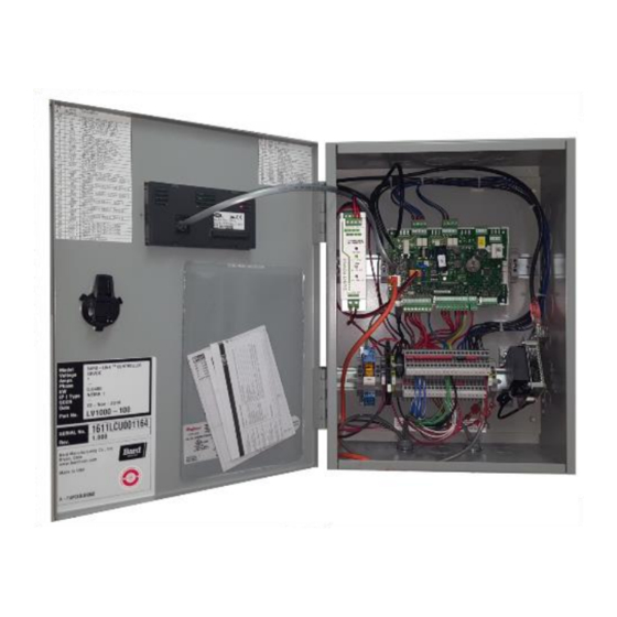
LV1000 CONTROLLER INSTALLATION FIGURE 1.1 Typical LV1000 Component Location RJ11 Cable to Display -48VDC to 24V Power Supply Control Board Shelter Inputs Power Loss Relay and Outputs Power Supply Connections Terminal Block Connection Page 7 of 36... -
Page 8: Lv1000 Fused Power Supply Terminal
LV1000 Controller Figure 1.2. The LV1000 controller is part of the Free Cooling Unit system by Bard. It is used to control up to four (4) wall-mount air conditioners from one controller. FIGURE 1.2 The microprocessor control provides an easy-to-read LV1000 Fused Power Supply Terminal interface with large LCD graphical display. -
Page 9: Remote Indoor Sensor Installation
2. Installing Remote Indoor Temperature/Humidity Sensor(s) One remote indoor temperature/humidity sensor and 35' of 18 gauge shielded cable is included with the controller. This sensor must be installed for proper operation. Mount the temperature/humidity sensor in a location least likely to be affected by open doors, rack-mounted fans, radiant heat sources, etc. -
Page 10: Additional Remote Sensor Installation
For proper operation, the remote indoor temperature/humidity sensor must be configured properly with the controller. If only the single remote indoor temperature/humidity sensor supplied with the controller is installed, the configuration setting is "0". This is the default setting. Up to two additional temperature and humidity sensors can be purchased and installed. - Page 11 3. Additional LV1000 Connections There are factory-installed jumpers across terminals #8 and #9 (smoke detector), #10 and #11 (hydrogen detector) and #12 and #13 (generator run). Remove the factory-installed jumpers before connecting to the detectors and/or generator (if applicable). INPUTS LV1000 Connections Sensor Connections Description...
-
Page 12: (Daisy Chain Method)
4. Communication Wiring Connect the communication wiring from the wall-mount units to the controller in the manner shown in Figures 1.5, 1.6 or 1.7. The communication wire should be 2-wire, 18 gauge shielded cable with drain. Any color can be used. Be sure to match "+"... -
Page 13: Figure 1.7 Communication Wire Filter Placement
FIGURE 1.7 Placement of Communication Wire Filters (Daisy Chain and Alternate Methods) Daisy Chain Wiring (up to four units) Place filter here Place filter here LV1000 Unit 1 Unit 2 Unit 3 Unit 4 Alternate Wiring (up to four units) Place filter here Place filter here LV1000*... -
Page 14: Figure 1.8 Wiring: Communication Wiring: Controller Termination
The steps outlined on the following pages show how to connect the communication wiring using the daisy chain method shown in Figure 1.5. If using the alternate method (as shown in Figure 1.6), the connections to the controller and each wall-mount unit will be the same but the filters need to be placed in the positions shown in Figure 1.7. -
Page 15: Figure 1.9 Wiring: Communication Wiring: 1St Unit Termination
FIGURE 1.9 Communication Wiring: Termination at the First Wall-Mount Unit Unit 1 Terminal Block 9 10 16 17 – From LV1000 Controller From the controller, extend the shielded cable through a separate conduit and route to the provided terminal block next to the wall-mount control board. -
Page 16: Figure 1.10 Wiring: Communication Wiring: Additional Unit Termination
FIGURE 1.10 Communication Wiring: Termination at Additional Wall-Mount Units Unit 2 Terminal Block 9 10 16 17 – From Wall-Mount Unit 1 Route the cable from the first wall-mount unit to the terminal block of the second wall-mount unit. If this is the last unit to be connected, make a small service loop Wall-Mount Unit 2 and attach EMI filter as shown. -
Page 17: Figure 1.11 Controller Circuit Install
Figure 1.12. Failing to ground the controller box properly could result in damage to the equipment. FIGURE 1.11 LV1000-100 Controller Supply Wiring The controller requires a separate -48VDC power supply, an additional 5-amp DC breaker (field supplied) and minimum 16 gauge supply wire. - Page 18 TABLE 1.1 Terminal Block Index Wire Wire Description Description Mark Mark 48VDC +Input Temperature Sensor 1 48– 48VDC – Input Ground Ground Temperature Sensor 2 24VDC + Ground 24VDC – Temperature Sensor 3 24VDC + Ground 24– 24VDC – VDC+ Sensor Power Distribution Smoke Detector Input VDC+...
-
Page 19: Figure 1.13 Wiring: Lv1000 Wiring Diagram
FIGURE 1.13 LV1000 Wiring Diagram Page 19 of 36... -
Page 20: System Start-Up
SYSTEM START-UP Before the Bard Free Cooling Unit system can be set up The TEC-EYE diagnostic tool is shipped inside the for operation, each wall-mount unit must have already controller. See FUSION-TEC manual 2100-670 for been installed, given a unique address and had a run more information on using the TEC-EYE test performed (see FUSION-TEC manual 2100-670). -
Page 21: Figuer 1.15 Quck Menu Icons
3) Press UP or DOWN keys to scroll to IO Config; press ENTER key. SYSTEM SET-UP 4) Press UP or DOWN keys to scroll to Indoor Use the LV controller to set-up the Bard Free Cooling Humidity 1 (C3). Unit system. 5) Press ENTER key to scroll to Enable (see 1. -
Page 22: Figure 1.18 Configuring Indoor Humidity 2 Sensor
FIGURE 1.19 To enable/disable Indoor Humidity 2: Configuring Indoor Humidity 3 Sensor 1) Press MENU key to go to the Main Menu screen. 2) Press UP or DOWN keys and ENTER key to enter USER password 2000. 3) Press UP or DOWN keys to scroll to IO Config; press ENTER key. -
Page 23: Figure 1.21 Configuring Indoor Temp 2 Sensor
4) Press UP or DOWN keys to scroll to Unit Setup 6) Press UP or DOWN key to change value to ON (A1); press ENTER key. to enable sensor (or change value to OFF to disable sensor). 5) Press ENTER key to scroll to Total Units (see Figure 1.23). -
Page 24: Figure 1.24 Verifying Units
FIGURE 1.24 Verifying Units 5. Complete Installation Once all the installation steps have been completed, all alarms have been cleared and system verification and run test results were satisfactory, the installation can now be considered “complete". Additional programming information can be found in the Service Instructions section of this manual. -
Page 25: Section 2: Service Instructions
SECTION 2: SERVICE INSTRUCTIONS Page 25 of 36... -
Page 26: Alarms
ALARMS Quick Menu FIGURE 2.1 Adjusting Alarm Setpoints Alarm Adjustment Acknowledging/Clearing Alarms Alarm conditions activate a red LED indicator that backlights the ALARM function key. As an option, an alarm condition may also be enunciated by an audible alarm signal. An alarm is acknowledged by pressing the ALARM key. - Page 27 To adjust the high temperature alarm setpoint: To adjust the high temperature 2 alarm setpoint: 1. Press MENU key to go to the Main Menu screen. 1. Press MENU key to go to the Main Menu screen. 2. Use UP or DOWN keys and ENTER key to enter 2.
-
Page 28: Figure 2.2 Changing Input Values
alarm installation instructions for specific wiring 3. Press UP or DOWN keys to scroll to IO Config; information. This alarm will automatically clear when press ENTER key. the smoke detector no longer indicates smoke is 4. Press UP or DOWN keys to scroll to Digital In present. -
Page 29: Figure 2.3 Adjusting Units Running When Generator Is Active
To change which units run when the generator run 7. Press ENTER key to save the value and move input is active: cursor to Unit 2. 1. Press MENU key to go to the Main Menu screen. 8. Press UP or DOWN keys and ENTER key to change units to Disabled on Gen as needed. -
Page 30: Figure 2.5 Changing Output Values
2. Use UP or DOWN keys and ENTER key to enter Anti-Theft Alarm USER password 2000. The LV will indicate a theft alarm when the Bard Guard 3. Press UP or DOWN keys to scroll to IO Config; anti-theft controller indicates an alarm to the anti- press ENTER key. -
Page 31: Humidifier Output
Humidifier Output The LV has the option to control a humidifier through a relay output. The output will close when a humidity call from the LV is active and open when the call is no longer present. The output can be configured to operate in reverse where the contacts will open when a humidity call is present and close when the call is no longer present. -
Page 32: Control Operation
CONTROL OPERATION FIGURE 2.6 Temperature Control Adjusting Setpoints Control Value Averaging The system requires one temperature and humidity sensor (included with LV) to operate. It allows a total of three temperatures and three humidity sensors to be connected to the LV for better representation of what is happening in the shelter. - Page 33 TABLE 2.2 Cooling Staging 1 Unit Order Freecooling Available Freecooling Not Available Unit 1 Freecooling Unit 1 Compressor Stage 1 Unit 1 Compressor Stage 1 Unit 1 Compressor Stage 2 Unit 1 Compressor Stage 2 2 Units Order Freecooling Available Freecooling Not Available Unit 1 Freecooling Unit 1 Compressor Stage 1...
-
Page 34: Humidity Control
5. Press ENTER key to scroll to Time Based (see been above or below the setpoint. Using these two Figure 2.7). considerations, the controller will generate a heating demand. The heating demand is a value between 0 and 6. Press UP or DOWN key to change the value from 100%. -
Page 35: Fan Control
TABLE 2.3 10. Press UP or DOWN keys to adjust value. Heating Staging 11. Press the ESCAPE key several times to return to Main Menu screen. 1 Unit FIGURE 2.8 Order Heat Method Adjusting Setpoints Unit 1 Heat Strip 2 Units Order Heat Method Unit 1 Heat Strip... -
Page 36: Additional Programming
ADDITIONAL PROGRAMMING LV1000 Menus/Screens Calibrating Sensors Main Menu 1. Press MENU key to go to the Main Menu screen. Press the MENU key from any screen to return to the 2. Use UP or DOWN keys and ENTER key to enter Main Menu.
Need help?
Do you have a question about the LV1000-100 and is the answer not in the manual?
Questions and answers