Table of Contents

Related Manuals for Bard MC4002


Summary of Contents for Bard MC4002
-
Page 1: Mc4002 General Information Figure
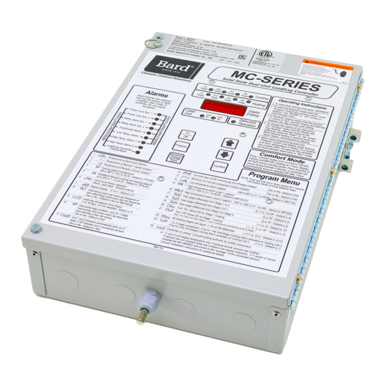
INSTALLATION INSTRUCTIONS & REPLACEMENT PARTS LIST MC4002 SERIES SOLID STATE DUAL UNIT LEAD/LAG CONTROLLER Bard Manufacturing Company, Inc. Manual : 2100-614I Bryan, Ohio 43506 Supersedes: 2100-614H Date: 7-13-18 www.bardhvac.com Page 1 of 43... -
Page 2: Table Of Contents
CB5000 Comm. Board ......24 Specifications/Features for Alarm Boards Figure 7 Controller Connections 1-Stage (WA/WL, W**A/ MC4002-A with Optional Base Alarm ....6 W**L Series) A/C-Older EIFM Econo ...25 MC4002-B with Enhanced Version Alarm ....6 Figure 8 Controller Connections 2-Stage (WA*S/WL*S .. -
Page 3: Getting Other Information And Publications Figures
American Society of Heating, Refrigerating, and Air Conditioning Engineers, Inc. 1791 Tullie Circle, N.E. Atlanta, GA 30329-2305 Telephone: (404) 636-8400 Fax: (404) 321-5478 BARD Bard Manufacturing Company, Inc. 1914 Randolph Drive Bryan, OH 43506 Telephone: (419) 636-1194 Fax: (419) 636-2640 Manual 2100-614I... -
Page 4: Shipping Damage
The equipment covered in this manual is to be installed by trained, experienced service and installation The MC4002 can be equipped with one of two alarm technicians. Please read entire manual before boards, and these can be factory-installed or installed proceeding. -
Page 5: Specifications/Features For Basic Controller
The controller is designed to accept 1 or 2 additional sensors 1 hour and those have 35-foot leads. The Bard part number for the •Dead band (difference between cooling and heating optional sensor with 35-foot leads is 8612-023A. These can setpoints): 2F to 40F (1.1C to 22.2C) -
Page 6: Figure
The on-board sensor is ignored if NOTE: If this alarm board was not originally factory two (2) or more sensors are connected to the Local, Rem installed, it can be field-installed at anytime. Bard 1 or Rem 2 sensor inputs. part number is AB3000-A. -
Page 7: Figure
“R” terminal on the blower control. The electronic blower control will now function as an on-off relay with The MC4002 is powered from the air conditioners that it no off-delay, and the blower motor will stop running is controlling, 24 VAC (18-32V) low voltage only. -
Page 8: General Programming Overview
GENERAL PROGRAMMING OVERVIEW MC4002 CONTROLLER BUTTONS AND FUNCTION On/Off Button Press and release the On/Off button to turn On controller, 4-character display will illuminate and Lead unit LED will light. Press and release the On/Off button to turn Off controller. Controller will go dark and A/C units will stop. -
Page 9: Humidity Control Option
H1 and H2 on the main for cooling the blower of the lead unit will come on controller board. Recommended Bard Part #8403-038 immediately (if not already on – See Blower Operation), (H600A 1014). Both HVAC units must be equipped and the Stage 1 LED will blink for 10-seconds before with electric heat for this sequence to work properly. - Page 10 outdoor temperature and humidity conditions are below operate as long as outdoor conditions are acceptable, the setpoint of the economizer control the lead unit and the compressor will operate. economizer will operate instead of the compressor. If cooling setpoint is 2F (default setting, user outdoor conditions are not acceptable for free cooling selectable 2-3F) warmer than Stage 3.
-
Page 11: Cooling Operating Sequences
economizer control the lead unit economizer will cooling setpoint is 4F (default setting, user operate instead of the compressor. If outdoor conditions selectable 2-6F) warmer than Stage 1, at which time are not acceptable for free cooling the compressor will the lead unit compressor will switch to compressor automatically operate on compressor Stage 1 partial Stage 2 full capacity. - Page 12 3. 1-Stage Compressor Units with Newer operate instead of the compressor. If outdoor conditions ECONWMT or WECOP Economizers (See Note A) are not acceptable for free cooling the compressor will automatically operate on compressor Stage 1 partial stage cooling setpoint is the setting (SP) input into capacity instead of the economizer.
-
Page 13: Heating Sequence Of Operation
2F (default setting, user 2. Heat Pumps with Electric Heat selectable 2-3F) warmer than Stage 3. On a call for 4 When the MC4002 controller is configured for heat Stage cooling the lag unit Y2 cooling output turns on pump installations the 2 -stage (Y2) outputs for both activating the compressor. -
Page 14: Specifications Opt. Remote Comm. Board
CB5000 Communication Board 1. Connect CAT 5 or CAT 6 Ethernet cable from NOTE: If the communication board (Bard part number computer to Ethernet port on the CB5000. CB5000) was not originally factory installed, it can be 2. Change the computer’s IP address as shown below field installed at anytime. - Page 15 3. Temperatures: Average temperature (if more than one sensor used, if not will read same as Local sensor) 1. Type “Admin” for user name and “Bard” for b. Local sensor at controller password. These are case sensitive. Hit “Log In”.
- Page 16 Setpoints Page If Network Uses Static IP Addressing 1. Enter the correct address information provided by the IT department and click the “Save Config” MC4000 HVAC Monitor / Controller button. 2. The assumption is that the new IP address has already been configured into the network to get through any firewall(s).
- Page 17 IP address saved and operating characteristics and has access to in the MIB file. MIB files are available on the Bard only Log In, System Status, Setpoints and Log Out website at http://bardhvac.com/software-download.
-
Page 18: Controller Wiring
CONTROLLER WIRING GENERATOR RUN FEATURE If desired, the MC4002 controller can be signaled The MC4002 can be used for controlling two (2) air conditioners with or without economizers. It can from a standby generator system to lockout (disable also be configured for two (2) heat pumps without operation) of the lag air conditioning system. -
Page 19: Figure 1
TABLE 1 Hook-Up Diagram Selection Table – Reference Figure 1 Shown Newer Older EIFM Older EIFM Newer MC4002-A or MC4002-B Economizer System Model Economizer – No Economizer with Economizer – No with Communication with CB5000 Type Series Economizer Communication Communication Communication Board –... -
Page 20: Controller Connections 1-Stage (W**Aa/ W**La Series) A/C W/No Economizers
NOTE: ALL SENSORS ARE SILVER OPTIONAL FIELD INSTALLED POLARITY SENSITIVE. COPPER 35 FOOT TEMPERATURE LEAD MUST CONNECT TO COPPER SENSORS, BARD PART CU, AND SILVER LEAD TO AG. REM 2 NUMBER 8612-023A SILVER GENERATOR RUN ALARM REMOVE JUMPER "NC" CONTACTS - OPEN ON ALARM... -
Page 21: Controller Connections 2-Stage (Wa*S/Wl*S Series) A/C - No Economizers
FIGURE 3 Controller Connections 2-Stage (WA*S/WL*S Series) Air Conditioners – No Economizers Manual 2100-614I Page 21 of 43... -
Page 22: Controller Connections 1-Stage (Wa/Wl, W**A/ W**L Series) A/C - No Econo With Alarm Board & Cb5000 Comm. Board
FIGURE 4 Controller Connections 1-Stage (WA/WL, W**A/W**L Series) Air Conditioners – No Economizers with Alarm Board & CB5000 Communication Board Manual 2100-614I Page 22 of 43... -
Page 23: Figure 5
SILVER OPTIONAL FIELD INSTALLED POLARITY SENSITIVE. COPPER 35 FOOT TEMPERATURE LEAD MUST CONNECT TO COPPER CU, AND SILVER LEAD TO AG. SENSORS, BARD PART REM 2 NUMBER 8612-023A SILVER GENERATOR RUN ALARM REMOVE JUMPER "NC" CONTACTS - OPEN ON ALARM... -
Page 24: Controller Connections 2-Stage (Wa*S/Wl*S Series) A/C - No Econo With Alarm Board & Cb5000 Comm. Board
FIGURE 6 Controller Connections 2-Stage (WA*S/WL*S Series) Air Conditioners – No Economizers with Alarm Board & CB5000 Communication Board Manual 2100-614I Page 24 of 43... -
Page 25: Controller Connections 1-Stage (Wa/Wl, W**A/ W**L Series) A/C-Older Eifm Econo
FIGURE 7 Controller Connections 1-Stage (WA/WL, W**A/W**L Series) Air Conditioners with Older Style EIFM Economizers Manual 2100-614I Page 25 of 43... -
Page 26: Series) A/C-Older Style Eifm Econo
FIGURE 8 Controller Connections 2-Stage (WA*S/WL*S Series) Air Conditioners with Older Style EIFM Economizers Manual 2100-614I Page 26 of 43... -
Page 27: Controller Connections 1-Stage (Wa/Wl, W**A/ W**L Series) A/C W/Older Style Eifm Econo & W/Alarm Board/Cb5000 Comm. Board
FIGURE 9 Controller Connections 1-Stage (WA/WL, W**A/W**L Series) Air Conditioners with Older Style EIFM Economizers and with Alarm Board & CB5000 Communication Board Manual 2100-614I Page 27 of 43... -
Page 28: Series) A/C W/Older Style Eifm Econo & W/Alarm Board/Cb5000 Comm. Board
FIGURE 10 Controller Connections 2-Stage (WA*S/WL*S Series) Air Conditioners with Older Style EIFM Economizers and with Alarm Board & CB5000 Communication Board Manual 2100-614I Page 28 of 43... - Page 29 FIGURE 11 Controller Connections 1-Stage (WA/WL, W**A/W**L Series) Air Conditioners with ECONWMT Economizers Manual 2100-614I Page 29 of 43...
-
Page 30: Figure 12
NOTE: ALL SENSORS ARE OPTIONAL FIELD INSTALLED SILVER POLARITY SENSITIVE. COPPER 35 FOOT TEMPERATURE LEAD MUST CONNECT TO COPPER SENSORS, BARD PART CU, AND SILVER LEAD TO AG. REM 2 NUMBER 8612-023A SILVER GENERATOR RUN ALARM REMOVE JUMPER "NC" CONTACTS - OPEN ON ALARM... - Page 31 FIGURE 13 Controller Connections 2-Stage (WA*S/WL*S Series) Air Conditioners with ECONWMT Economizers Manual 2100-614I Page 31 of 43...
- Page 32 FIGURE 14 Controller Connections 1-Stage (WA/WL, W**A/W**L Series) Air Conditioners with ECONWMT Economizers and with Alarm Board & CB5000 Communication Board Manual 2100-614I Page 32 of 43...
- Page 33 NOTE: ALL SENSORS ARE OPTIONAL FIELD INSTALLED SILVER POLARITY SENSITIVE. COPPER 35 FOOT TEMPERATURE LEAD MUST CONNECT TO COPPER SENSORS, BARD PART CU, AND SILVER LEAD TO AG. REM 2 NUMBER 8612-023A SILVER GENERATOR RUN ALARM REMOVE JUMPER "NC" CONTACTS - OPEN ON ALARM...
- Page 34 FIGURE 16 Controller Connections 2-Stage (WA*S/WL*S Series) Air Conditioners with ECONWMT Economizers and with Alarm Board & CB5000 Communication Board Manual 2100-614I Page 34 of 43...
- Page 35 FIGURE 17 Controller Connections Heat Pumps – No Economizers Manual 2100-614I Page 35 of 43...
- Page 36 FIGURE 18 Controller Connections Heat Pumps – No Economizers and with Alarm Board & CB5000 Communication Board Manual 2100-614I Page 36 of 43...
-
Page 37: Alarm Wiring
E and F from the alarm board to the specified terminals NOTE: The LED display board can be replaced if on the air conditioner 24V terminal block. needed independently of the alarm board. Bard part number is 8612-022. Note: The E and F wiring connections at the 24V... - Page 38 FIGURE 19 ALARM BOARD CONNECTIONS FOR NORMALLY CLOSED "NC" OPEN-ON-ALARM STRATEGY Note 1: 2nd Stage, Econ 1, Econ 2, High Temp 2 and Controller alarms are only on -B alarm board. All other alarms are on both -A and -B alarm boards. IMPORTANT LED display board is shipped loose to protect it from possible damage during installation of the wiring to main controller board and/or the alarm board.
-
Page 39: No" Close-On-Alarm Strategy
FIGURE 20 ALARM BOARD CONNECTIONS FOR NORMALLY OPEN "NO" CLOSE-ON-ALARM STRATEGY Note 1: 2nd Stage, Econ 1, Econ 2, High Temp 2 and Controller alarms are only on -B alarm board. All other alarms are on both -A and -B alarm boards. IMPORTANT LED display board is shipped loose to protect it from possible damage during installation of the wiring to main controller board and/or the alarm board. -
Page 40: Programming Instructions
Change button will result is display showing “Locd” indicating controller is locked. See section on Security (Locking) Feature. See next page for Programmable Features, Default Settings and MC4002 front panel label layout. NOTE: When using the controller buttons to review settings or making changes, push and hold the buttons for approximately 1 second or until the display changes. -
Page 41: Mc Series Label
MC Series Solid State Dual Unit Lead Lag Controller Operating Instructions Cooling Stage Stage Stage Stage 1. To swap lead and lag units press “ADVANCE” . 2. To enter the Program mode press the Heating Stage Stage Stage Stage “Program” button and release it when “Pro9” appears. - Page 42 FIGURE 21 PARTS LIST DESCRIPTION DIAGRAM MIS-2954 B Manual 2100-614I Page 42 of 43...
-
Page 43: Parts List
Parts List Dwg. Part No. Description MC4002 MC4002-A MC4002-AC MC4002-B MC4002-BC AB3000-A AB3000-B CB5000 127-343-4 Control Box 8612-043 Controller Board 8612-049 Alarm Board A* 8612-050 Alarm Board B* 8612-022 Alarm Display 113-430-4 Support Bracket 152-625-4 Control Box Door 8611-099 LTF Fitting...
Need help?
Do you have a question about the MC4002 and is the answer not in the manual?
Questions and answers