Table of Contents
Advertisement
Available languages
Available languages
Quick Links
Advertisement
Chapters
Table of Contents

Related Manuals for Zehnder Rittling ComfoSwitch C Series


Summary of Contents for Zehnder Rittling ComfoSwitch C Series
- Page 1 Handleiding ComfoSwitch C Manual ComfoSwitch C Betriebsaneitung ComfoSwitch C Manuel ComfoSwitch C Manuale ComfoSwitch C Instrukcja obsługi ComfoSwitch C Manual ComfoSwitch C Heating Cooling Fresh Air Clean Air ComfoSwitch C55 ComfoSwitch C67 ComfoSwitch CCH NL - 1...
- Page 2 fig./Abb./rys. 4.1 - ComfoSwitch C55 fig./Abb./rys. 4.2 - ComfoSwitch C67 fig./Abb./rys. 4.3 - ComfoSwitch C67mtb fig./Abb./rys. 4.4 - ComfoSwitch CCH (Jedn. went.) ComfoSwitch CAN_L CAN_L CAN_H CAN_H fig./Abb./rys. 4.5 2 - NL...
-
Page 3: Table Of Contents
Inhoud Inleiding ..................4 Veiligheid ..................5 Gebruik van de ComfoSwitch ............6 Basisfuncties ................. 6 Boost ..................... 6 Led-indicatoren ................7 Helderheid van de leds ..............7 Filterstatus ..................7 Storingswaarschuwingen.............. 8 Installatie ..................8 Ingebruikname ................8 Alle rechten voorbehouden Dit document is met uiterste zorg samengesteld. -
Page 4: Inleiding
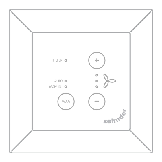
Knoppen Led-indicatoren FILTER-indicator. Tussen de AUTO-modus MODUS en MANUELE bediening AUTO-modusindicator. schakelen. MANUELE modusindicator. Het ventilatiedebiet verhogen. Debietindicatoren. De instellingen verhogen. Led 3 Led 2 Het ventilatiedebiet verlagen. De instellingen verlagen. Led 1 Inleiding Het apparaat kent 3 verschillende mod- ellen (zoals op de voorpagina weerge- De ComfoSwitch C (hierna genoemd 'ap- geven): ComfoSwitch CCH, C55 en C67. -
Page 5: Veiligheid
Gebruik van het TOESTEL garantievoorwaarden. Dit geldt ook voor Het TOESTEL mag uitsluitend worden normale slijtage. De fabrikant behoudt gebruikt als het correct is geïnstalleerd zich het recht voor de constructie en/of volgens de instructies en richtlijnen van de configuratie van zijn producten op ieder installatiehandleiding van het TOESTEL. -
Page 6: Gebruik Van De Comfoswitch
Gebruik van de knoppen worden ingedrukt, dimmen alle led-indicatoren naar de ingestelde ComfoSwitch helderheid. Als de ingestelde helderheid op maximaal gedimd is ingesteld, moet één van de knoppen worden ingedrukt 3.1 Basisfuncties om het paneel te activeren. De functie van de ingedrukte knop wordt niet uitgevoerd. -
Page 7: Led-Indicatoren
Led-indicatoren Helderheid van de leds De werkelijke debietstatus wordt als volgt via de leds weergegeven: De helderheid van de led-indicatoren kan Led 1 Led 2 Led 3 Debiet in 6 verschillende helderheidsniveaus Instelling worden afgesteld, inclusief 'off'. Deze AFWEZIG instelling is Instelling 1 gelijk voor alle led-indicatoren. -
Page 8: Storingswaarschuwingen
Storingswaar- het gewenste design-frame X en stel de maat van het venster (D) af. schuwingen 4. Sluit de communicatiekabel (fig. 4,5) op het ventilatietoestel en het apparaat aan. Led 1 Led 2 Led 3 Menuonder- deel 5. De eisen betreffende de kabel zijn: ■... - Page 9 Contents Introduction ................. 10 Safety ................... 11 Use of the ComfoSwitch ............. 11 Basic functions ..............11 Boost ................... 12 LED indications ................12 LED brightness ................12 Filter status .................. 13 Malfunction alerts ................ 13 Installation ................... 13 Commisioning................13 All rights reserved This document has been compiled with the utmost care.
-
Page 10: Introduction
Buttons LED indicators Switch between AUTO mode FILTER indicator. MODE and MANUAL operation. AUTO mode indicator. Increase the ventilation airflow. MANUAL mode indicator. Increase settings. Air flow indicators. Decrease the ventilation LED 3 airflow. LED 2 Decrease settings. LED 1 Introduction With these 3 variants the device can be built into almost every standard frame. -
Page 11: Safety
■ persons with reduced mental Disconnect the ventilation unit from the capabilities; main power before opening the housing ■ persons with lack of experience of the device. and knowledge, if they have been given supervision or Questions instruction concerning use Please contact the supplier if you of the unit in a safe way and have any questions. -
Page 12: Boost
LED indications When AUTO mode is active any adjustments will be overruled by the next programmed scheduler step. If no schedule has been programmed, the adjustment will be active for two hours. Schedules The actual air flow status is displayed cannot be set on the Comfoswitch, this has to be done on another using the LEDs as follows: device as e.g. -
Page 13: Filter Status
3. Press MODE to confirm or During assembly, ensure that ALL Press and hold MODE to cancel screws are tight. the operation. If ordered (fig 4.1 - 4.5): When no button is operated for 1. Attach the wall-mounting casing I 10 seconds any adjustment made is with the plugs H and screws G to cancelled. - Page 14 Inhalt Einführung ................... 15 Sicherheit ..................16 Verwendung des ComfoSwitch ..........16 Grundlegende Funktionen ........... 16 Boost ................... 17 LED-Anzeigen ................17 LED-Helligkeit ................18 Filterstatus ................... 18 Störungsmeldungen ..............18 Installation ................... 18 Inbetriebnahme ................19 Alle Rechte vorbehalten. Dieses Dokument wurde mit äußerster Sorgfalt zusammengestellt.
-
Page 15: Einführung
Tasten LED-Anzeigen FILTER-Anzeige Umschaltung zwischen dem MODUS AUTO-Modus und dem AUTO-Modusanzeige MANUELLEN Betrieb MANUELL-Modusanzeige Erhöhung des Luftstroms Luftstromanzeigen Verringerung des Luftstroms LED 3 LED 2 LED 1 Einführung Es stehen zwei verschiedene Varianten des Geräts zur Verfügung (siehe Beim ComfoSwitch C (nachstehend als Vorderseite): C55, C67. -
Page 16: Sicherheit
■ Kindern ab 8 Jahren gilt auch für den normalen Verschleiß ■ Personen mit eingeschränkten und die normale Abnutzung. Der körperlichen Fähigkeiten Hersteller behält sich das Recht vor, ■ Personen mit eingeschränkten jederzeit Konstruktionsänderungen und/ sensorischen Fähigkeiten oder Konfigurationsänderungen seiner ■... -
Page 17: Boost
Mit dem ComfoSwitch können Sie Einschalten der Boost-Funktion folgende Aktionen durchführen: 1. Drücken und halten Sie 3 Sekunden lang die Taste +. LED 1 und LED 2 MODUS Umschaltung zwischen leuchten und LED 3 blinkt AUTO und MANUELL ■ AUTO: Die Einheit Ausschalten der Boost-Funktion Die Boost-Funktion schaltet nach ändert die Einstellungen... -
Page 18: Led-Helligkeit
Filterstatus ■ MANUELL-Anzeige an: Lüftung im MANUELLEN Modus Der Filterstatus wird durch die Filter-LED ■ AUTO-Anzeige an und dargestellt: MANUELL-Anzeige langsam ■ AUS: Filter OK / keine Störung blinkend: ■ BLINKEND: Filterbestellung nötig Es ist eine manuelle ■ EIN: Filteraustausch nötig Luftstromeinstellung aktiv, die vom nächsten programmierten Störungsmeldun-... -
Page 19: Inbetriebnahme
10 Inbetriebnahme (Abb. 4.1 - 4.4): 1. Bringen Sie das Schalten Sie die Spannungsversorgung Wandmontagegehäuse (I) (falls der Lüftungseinheit EIN. Wenn das Gerät bestellt) mit den Dübeln (H) und das erste Mal startet, blinken LED 1, Schrauben (G) an der Wand an LED 2 und LED 3. - Page 20 Table des matières Introduction ................. 21 Sécurité ..................22 Usage du ComfoSwitch C............23 Fonctions basiques ............. 23 Boost ................... 23 Indications DEL ................23 Luminosité de DEL ..............24 État du filtre ................. 24 Alertes de dysfonctionnements ..........24 Installation ...................
-
Page 21: Introduction
Boutons Indicateurs DEL Indicateur FILTRE. Alternez entre le mode AUTO MODE et le fonctionnement en mode Indicateur de mode AUTO. MANUEL. Indicateur de mode MANUEL. Augmentez le débit d'air de ventilation. Indicateurs de débit d'air. Augmentez les réglages. DEL 3 DEL 2 Réduisez le débit d'air de ventilation. -
Page 22: Sécurité
■ les enfants âgés de moins de Les coûts d'assemblage et de 8 ans; démantèlement sur site ne sont pas ■ les personnes présentant des couverts par les conditions de la capacités physiques diminuées ; garantie. C'est aussi le cas de l'usure ■... -
Page 23: Usage Du Comfoswitch C
Usage du sur une atténuation totale, on peut appuyer sur n’importe quel bouton pour ComfoSwitch C activer le panneau. Cette action ne modifie pas la fonction en cours. 3.1 Fonctions basiques Boost Le débit d'air de ventilation peut être réglé sur le maximum (BOOST) pendant 30 minutes. -
Page 24: Luminosité De Del
En l'absence d'activation d'un bouton DEL 1 DEL 2 DEL 3 Débit d'air pendant 10 secondes, tout ajustement Position 3 effectué est annulé. L'unité revient au (Haut) mode de fonctionnement normal. clignotement Boost lent État du filtre ON ou OFF selon la présélection du débit d'air active avant le démarrage du boost. -
Page 25: Installation
Installation ■ Vis en acier trempé et galvanisé 2,2 x12 PT10 ; Déconnectez l'unité de ventilation de ■ M2,2x 12 empreinte cruciforme l'alimentation principale avant d'installer plus-fix 45°. le dispositif. 7. Poussez le cache C en place. Respectez toujours la réglementation locale relative à... - Page 26 Indice Introduzione ................. 27 Sicurezza ..................28 Utilizzo di ComfoSwitch .............. 28 Funzioni di base ..............28 Boost ................... 29 Indicazioni LED ................29 Luminosità dei LED ..............30 Stato del filtro ................30 Avvisi di malfunzionamento ............30 Installazione ................. 30 Messa in funzione ...............
-
Page 27: Introduzione
Pulsanti Indicatori LED Indicatore FILTRO. Consente di alternare MODALITÀ tra modalità AUTO e Indicatore della modalità AUTO. funzionamento MANUALE. Indicatore della modalità Aumenta il flusso d'aria di MANUALE. ventilazione. Aumenta il valore delle Indicatori del flusso d'aria impostazioni. LED 3 Riduce il flusso d'aria di LED 2 ventilazione. -
Page 28: Sicurezza
manuale d'installazione dell'unità. L'unità riserva il diritto di modificare la struttura può essere utilizzata da: e/o la configurazione dei suoi prodotti ■ bambini con un'età minima di in qualsiasi momento senza obbligo di 8 anni; modificare i prodotti precedentemente ■ persone con ridotte capacità consegnati. -
Page 29: Boost
Disattivare la funzione Boost MODALITÀ Alternare tra modalità La funzione Boost si disattiva AUTO e MANUALE. automaticamente dopo 30 minuti. ■ AUTO: l'unità cambia Per disattivare direttamente il timer Boost: automaticamente le 1. Premere il tasto + o -. La funzione impostazioni in base Boost si disattiva e il dispositivo ai programmi orari... -
Page 30: Luminosità Dei Led
Avvisi di del programma orario definito. Se non è stato definito alcun malfunzionamento programma, la regolazione sarà attiva per due ore. LED 1 LED 2 LED 3 Voce di menu Quando la sonda di ventilazione integrata della HRU o una sonda esterna Inizializzazi- richiede un flusso d'aria maggiore HRU /... -
Page 31: Messa In Funzione
3. Far passare il cavo di comunicazione attraverso la placca X con il design desiderato e il profilo di adattamento (D). 4. Collegare il cavo di comunicazione (fig. 4.5), per connettere l'unità di ventilazione e il dispositivo. 5. I requisiti del cavo sono: ■... - Page 32 Spis treści Wprowadzenie ................35 Bezpieczeństwo ................34 Korzystanie z ComfoSwitch ............34 Funkcje podstawowe ............34 Przewietrzanie ................35 Wskazania diod LED ..............35 Jasność diod LED ............... 36 Status filtrów ................36 Powiadomienia o usterkach ............36 Instalacja ..................37 Uruchomienie ................
-
Page 33: Wprowadzenie
Przyciski Wskaźniki LED Przełączanie pomiędzy Wskaźnik FILTR. TRYB trybem AUTO a trybem Wskaźnik trybu AUTO. MANUALNYM. Wskaźnik trybu RĘCZNE. Zwiększenie strumienia powietrza wentylacji. Wskaźniki przepływu powietrza. Zwiększenie ustawień. Dioda LED 3 Dioda LED 2 Zmniejszenie strumienia powietrza wentylacji. Dioda LED 1 Zmniejszenie ustawień. -
Page 34: Bezpieczeństwo
Bezpieczeństwo ■ dzieci w wieku od 8 lat; ■ osoby o ograniczonych Należy zawsze przestrzegać przepisów zdolnościach fizycznych; bezpieczeństwa zamieszczonych ■ osoby o ograniczonych w niniejszym dokumencie. zdolnościach zmysłowych; Nieprzestrzeganie przepisów ■ osoby o ograniczonych bezpieczeństwa, ostrzeżeń, uwag zdolnościach psychicznych; i instrukcji zawartych w niniejszym ■... -
Page 35: Przewietrzanie
Wyłączenie przewietrzania TRYB Przełączenie pomiędzy Przewietrzanie wyłączy się trybem AUTO a automatycznie po upływie 30 minut. MANUALNY Aby bezpośrednio wyłączyć zegar ■ AUTO: urządzenie zmieni przewietrzania: ustawienia automatycznie 1. Naciśnij przycisk + lub -. zgodnie z ustawionymi Przewietrzanie zostanie wyłączone, fabrycznie programami a urządzenie powraca do wentylacji;... -
Page 36: Jasność Diod Led
Status filtrów wskaźnik MANUAL miga powoli: Aktywna jest ręczna regulacja Status filtrów jest reprezentowany przez przepływu powietrza, która wskaźnik LED filtrów: zostanie zastąpiona przez ■ WYŁ.: filtr OK / brak awarii; następny zaprogramowany ■ MIGA: wymagane zamówienie krok programu wentylacji. filtra;... -
Page 37: Instalacja
Instalacja 7. Dociśnij pokrywę C na swoje miejsce. Przed zainstalowaniem urządzenia należy odłączyć jednostki wentylacyjną 10 Uruchomienie od zasilania głównego. Włącz główne zasilanie jednostki Należy zawsze przestrzegać lokalnych wentylacyjnej. Podczas pierwszego przepisów bezpieczeństwa. uruchomienia urządzenia migają diody Podczas montażu należy upewnić się, LED 1, LED 2 i LED 3. - Page 38 Índice Introducción ................39 Seguridad ..................40 Uso de ComfoSwitch ..............41 Funciones básicas............... 41 Boost (Amplificación) ..............41 Indicadores LED ................42 Brillo de los LED ................42 Estado de los filtros ..............42 Alertas de fallo de funcionamiento ..........43 Instalación ...................
-
Page 39: Introducción
Botones Indicadores LED. Cambia entre Indicador FILTER. MODO funcionamiento en modo Indicador de modo AUTO. AUTO y MANUAL. Indicador de modo MANUAL. Aumenta el caudal de ventilación. Indicadores de caudal de aire. Aumenta los valores a LED 3 definir. LED 2 Reduce el caudal de LED 1 ventilación. -
Page 40: Seguridad
la unidad. Pueden utilizar la unidad: productos en cualquier momento sin ■ niños a partir de los 8 años de obligación de modificar los productos edad; suministrados previamente. ■ personas con discapacidades Seguridad físicas; ■ personas con discapacidades Cumpla siempre la normativa de sensoriales;... -
Page 41: Uso De Comfoswitch
Uso de LED atenuarán su brillo al valor establecido. Si se ajusta el brillo al valor ComfoSwitch de atenuación total, es necesario pulsar alguno de los botones para activar el panel. La acción del botón pulsado se 3.1 Funciones básicas ignorará. -
Page 42: Indicadores Led
Indicadores LED Brillo de los LED El estado del caudal de aire real se El brillo de los indicadores LED se puede indica mediante LED del siguiente modo: ajustar a 6 niveles diferentes, incluyendo LED 1 LED 2 LED 3 Caudal de uno de apagado;... -
Page 43: Alertas De Fallo De Funcionamiento
Alertas de fallo de a la carcasa para montaje en pared (I) o a la placa de montaje (E). funcionamiento 3. Pase el cable de comunicación a través del bastidor con el diseño X y vuelva a dimensionar la ventana LED 1 LED 2 LED 3... - Page 44 Österreich (Austria) Wernig kunststoff- und lüftungstechnik Tel.: 04227.22130 Nederland (The Netherlands) Internet: www.wernig.at Zehnder Group Nederland B.V. E-mail: office@wernig.at Lingenstraat 2, 8028 PM Zwolle Postbus 621, 8000 AP Zwolle Polska (Poland) Tel.: 0900 555 19 37 (€ 0.10 a minute, NL only) Zehnder Polska Sp.
Need help?
Do you have a question about the ComfoSwitch C Series and is the answer not in the manual?
Questions and answers