Advertisement
Table of Contents
Advertisement
Table of Contents

Related Manuals for Electrolux C240


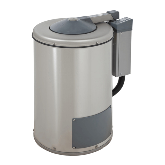
Summary of Contents for Electrolux C240
- Page 1 Operating and installation manual Hydro-extractor C240 / C240R C260 / C260R C290R 487 22 52 21.01...
-
Page 3: Table Of Contents
Hydro-extractors, drum volume 38 or 58 or 88 litres List of contents: Instruction for use: General, safety......................5 Procedure for use ...................... 6 Maintenance ......................7 Installation: Unpacking, open the lid, come with all types ............. 8 Positioning, drains...................... 9 Quality requirements, concreting of foundation ............ -
Page 5: Instruction For Use
Instructions for use General The hydro-extractor is an invaluable complement to a washing machine and other drying equipment: It complements the washing machine by very efficient dewatering of the laundry after the wash programme is completed. It complements the tumble dryer or drying cabinet by considerably reducing the drying time. -
Page 6: Procedure For Use
Instructions for use Procedure for use Preparation Place the load in an even layer all around the drum Place long articles in a zig-zag fashion so that they are not stretched unnecessarily while being extracted. Place heavy items at the bottom and light items at the top. -
Page 7: Maintenance
Instructions for use Maintenance The below-mentioned intervals for maintenance apply in situations of normal use, e.g. a tenancy estate laundry. If the machine is used professionally, e.g. in a laundrette, this interval should be halved. Every 14 days It is important to carry out regular checks of the hydro extractor's function, particularly for personal safty reasons. -
Page 8: Unpacking, Open The Lid, Come With All Types
Installation Installation of hydro-extractor: With freely suspended basket Unpacking The hydro-extractor is protected against transport damage and bolted to a pallet before delivery. The transport protection consists of a wooden plug fitted between the pallet and the counterweight of the motor. Through the pallet and the wooden plug, a bolt has been entered to reach into the counterweight. -
Page 9: Positioning, Drains
Installation Installation of all types of hydro-extractor Positioning The extractor is to be placed as close to a floor drain or gutter as possible. The distance to the wall or other equipment must be at least 250 mm. The distance on the left side must be at least 250 mm. -
Page 10: Installation
Installation Installation of all types of hydro-extractor Quality requirements concerning the base The base must be very stable in order to absorb the dynamic forces transferred in the spinning process. Normally, the hydro-extractor can be attached by means of expansion bolts (size M12) directly into a concrete floor of good quality and adequate thickness - see bolt height B in the table below;... -
Page 11: Concreting, Procedure
Installation Installation of all types of hydro-extractor Concreting, procedure: • Cut out the floor approx. 75 mm down. Make sure that the sides of the hole have an ;;;;; outwards slope; the lower longitudinal dimension L must be 120 mm bigger than the dimension at the edge of the floor. -
Page 12: Attachment And Fitting Of Hydro-Extractor
Installation Attachment of hydro-extractor with freely suspended basket When using expander bolts use size M12. Bottom ring Drill holes in the floor. The depth and diameter must fit the expander bolts used. To position holes correctly you can use the template which is supplied. - Page 13 Installation Attachment of hydro-extractor with rigidly suspended basket 38 litres Position the hydro-extractor. Adjust the extractor to make it completely horizontal. Use gaskets made of stainless or galvanised metal plate to place under the feet of the machine. The gaskets must be big enough to cover the entire surface of the foot.
-
Page 14: Technical Data
Installation Technical data for hydro-extractors with 50 Hz and 60 Hz mains frequency Free Drum suspension Free Rigid Rigid Rigid suspension suspension suspension suspension suspension 38 L 58 L 38 L Basket volume in litres 58 L 88 L Basket Capacity [kg] (Dry garments) Basket Speed 50 Hz 1450... -
Page 15: Electrical Installation
Installation Electrical installation. Electrical Installation is to be carried out by an authorized electrician. Switch Fit a current switch prior to the extractor. The cable between switch and hydro-extractor must comply with at least HO5VV-F in accordance with CEE(13)53 and must hang in a loop. -
Page 16: Voltage Change
Installation Voltage change Voltage change must be done by authorized personnel. Some extractors have a dual voltage facility and can be changed over in connection with installation. An extractor, which upon delivery is connected for 400-415 V 3 AC (Y-connection), can be (∆) changed over to 230 V 3 AC (∆-connection) and vice versa... -
Page 17: Test Runs
Installation Test run When the installation work has been completed, a functional check must be carried out as follows: 1. Make sure that the main switch is in OFF position and that the drum is empty. Close the lid. 2. Turn the main switch ON. The green lamp for - button must now flash.
Need help?
Do you have a question about the C240 and is the answer not in the manual?
Questions and answers