Table of Contents
Advertisement
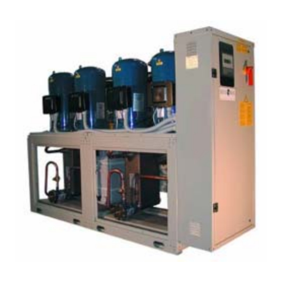
SIGMA 2002
42 ÷ 297 kW
Installation,
Installation,
Installation,
Installation,
Installation,
operating,
operating,
operating,
operating,
operating,
and maintenance
and maintenance
and maintenance
and maintenance
and maintenance
manual
manual
manual
manual
manual
Water chillers
Water chillers
Water chillers
Water chillers
Water chillers
Manual
Manual
Manual
Manual
Manual
Issue
Replaces
Water/water
Water/water
Water/water
Water/water
Water/water
self contained
self contained
self contained
self contained
self contained
ISO 9001 - Cert. n. 0201
101130A02
101130A02
101130A02
101130A02
101130A02
12.02
12.02
12.02
12.02
12.02
09.98
09.98
09.98
09.98
09.98
0062
0062
0062
0062
0062
Scroll compressors
Scroll compressors
Scroll compressors
Scroll compressors
Scroll compressors
Advertisement
Table of Contents

Related Manuals for Blue Box SIGMA 2002


Summary of Contents for Blue Box SIGMA 2002
- Page 1 SIGMA 2002 Manual Manual 101130A02 101130A02 101130A02 Manual Manual Manual 101130A02 101130A02 12.02 12.02 12.02 12.02 12.02 Issue 42 ÷ 297 kW 09.98 09.98 09.98 09.98 09.98 Replaces Installation, Installation, Installation, Installation, Installation, operating, operating, operating, operating, operating, and maintenance...
- Page 3 SIGMA 2002/LE/HP: motocondensing unit SIGMA 2002/LC: motoevaporating unit. SIGMA 2002 / LC /HP: motoevaporating unit ACCESSORY VERSIONS SIGMA 2002 /DC: unit with heat recovery condenser. SIGMA 2002 /DS: unit with desuperheaters SIGMA LN: low noise unit REFRIGERANT CIRCUIT ACCESSORIES HYDRAULIC CIRCUIT ACCESSORIES...
- Page 4 Version LC: remote air cooled condenser below the evaporating unit: TABLE 2 - PIPE DIAMETER FOR VERSIONS LC 4.9.8 Connection of Sigma 2002 LC/HP units to a remote air cooled condenser. TABLE 3 - CONNECTION PIPE EXTERNAL DIAMETERS FOR VERSIONS LC/HP 4.10 PRESSURE RELIEF VALVES 4.11...
- Page 5 High and low pressure alarms 8.2.13 Changeover from chiller to heat pump and vice versa 8.2.14 Desuperheater (Option) 8.2.15 Total heat recovery (only SIGMA 2002/DC) 8.2.16 Dual set-point (option) 8.2.17 Leaving water temperature control (option) 8.2.18 Defrost (heat pumps units /LC)
- Page 6 12.4 ENVIRONMENTAL CONSIDERATIONS DECOMMISSIONING THE UNIT REFRIGERANT CIRCUIT DIAGRAM DIMENSIONS, WEIGHTS AND HYDRAULIC CONNECTIONS Blue Box...
-
Page 7: Technical Characteristics
SIGMA 2002 - water chiller Water-cooled liquid chillers with hermetic scroll compressors and plate type evaporator, suitable for inside installations. TECHNICAL CHARACTERISTICS UNIT FRAME Self supporting frame, constructed in galvanized sheet steel with RAL 7032 powder paint baked at 180°C to provide a durable weatherproof finish. -
Page 8: Controls And Safety Devices
SIGMA 2002 /DC: unit with heat recovery condenser. Not available for HP versions. In addition to the components of version SIGMA 2002 this unit includes a 100% heat recovery condenser, for the production of hot water, and a liquid receiver on each refrigerant circuit. -
Page 9: Refrigerant Circuit Accessories
- Pallet/skid for shipment in a container - Non-standard RAL paint colours - Unit completely pre-assembled, the unit will be supplied without refrigerant charge, test and PED certificate. - Modular pre-asembled unit, only 4 compressors models, with the exception of model 14.4. Blue Box - 3... - Page 10 S E R I E S The SIGMA 2002 series of water cooled chillers, for installation inside the building, are available in various sizes with capacities from 42 to 297 kW. Model designations consist of two numbers: SIGMA 2002 16.4...
-
Page 11: Technical Data
Di men s i o n an d wei g h t Length 1.334 1.334 1.334 1.334 Width Heigth Shipping weight (*) evaporator entering/leaving temperature 12-7 °C; condenser entering/leaving temperature 30-35 °C (**) condenser entering/leaving temperature 40-45 °C; evaporator entering/leaving temperature 15-10 °C. Blue Box - 5... - Page 12 Di men s i o n an d wei g h t Length 1.334 1.356 1.356 1.356 Width Heigth 1.700 1.700 1.700 Shipping weight (*) evaporator entering/leaving temperature 12-7 °C; condenser entering/leaving temperature 30-35 °C (**) condenser entering/leaving temperature 40-45 °C; evaporator entering/leaving temperature 15-10 °C. Blue Box - 6...
- Page 13 Di men s i o n an d wei g h t Length 1.356 1.356 1.426 2.476 Width Heigth 1.700 1.700 1.787 1.700 Shipping weight (*) evaporator entering/leaving temperature 12-7 °C; condenser entering/leaving temperature 30-35 °C (**) condenser entering/leaving temperature 40-45 °C; evaporator entering/leaving temperature 15-10 °C. Blue Box - 7...
- Page 14 2.476 2.476 Width Heigth 1.700 1.700 1.700 1.700 Shipping weight 1.069 1.210 1.226 1.270 (*) evaporator entering/leaving temperature 12-7 °C; condenser entering/leaving temperature 30-35 °C (**) condenser entering/leaving temperature 40-45 °C; evaporator entering/leaving temperature 15-10 °C. Blue Box - 8...
-
Page 15: Electrical Characteristics
ELECTRICAL CHARACTERISTICS Refrigerant R407C MODEL SIGMA 2002 Maximum absorbed power 16,4 19,4 24,4 27,3 Maximum starting current Full load current Power supply V/f/Hz 400/3~/50 Control power supply V/f/Hz 230/~/50 MODEL SIGMA 2002 10.2 Maximum absorbed power 30,2 36,2 41,4 46,6... - Page 16 TECHNICAL DATA Refrigerant R22 MODEL SIGMA 2002 C o o l i n g ( * ) Nominal capacity 42,5 51,9 59,1 68,1 Evaporator water flow 2,03 2,48 2,823 3,253 (l/h) 7.309 8.928 10.162 11.710 Evaporator pressure drop 48,3 45,1...
- Page 17 TECHNICAL DATA Refrigerant R22 MODEL SIGMA 2002 10.2 C o o l i n g ( * ) Nominal capacity 77,1 88,5 104,5 120,5 Evaporator water flow 3,683 4,228 4,992 5,757 (l/h) 13.257 15.220 17.972 20.725 Evaporator pressure drop 33,4...
- Page 18 TECHNICAL DATA Refrigerant R22 MODEL SIGMA 2002 12.2 13.2 14.4 16.4 C o o l i n g ( * ) Nominal capacity 133,7 146,9 154,2 Evaporator water flow 6,389 7,021 7,365 8,455 (l/h) 23.000 25.275 26.514 30.440 Evaporator pressure drop...
- Page 19 TECHNICAL DATA Refrigerant R22 MODEL SIGMA 2002 18.4 20.4 24.4 26.4 C o o l i n g ( * ) Nominal capacity 267,4 293,9 Evaporator water flow 9,985 11,514 12,778 14,042 (l/h) 35.944 41.449 46.000 50.550 Evaporator pressure drop...
- Page 20 ELECTRICAL CHARACTERISTICS Refrigerant R22 MODEL SIGMA 2002 Maximum absorbed power 16,4 18,4 22,8 25,8 Maximum starting current Full load current Power supply V/f/Hz 400/3~/50 Control power supply V/f/Hz 230/~/50 MODEL SIGMA 2002 8 . 2 9 . 2 10.2 Maximum absorbed power...
-
Page 21: Sound Power And Pressure Levels
Lw: sound power values in free field conditions are calculated in accordance with ISO 3746. Lp : sound pressure values measured at 1 m from the unit in free field conditions in compliance with ISO 3746 Blue Box - 15... -
Page 22: Safety Precautions
- Pipe the discharge of the relief valves. - Do not work within the theoretical discharge trajectory of the relief valves. Blue Box - 16... -
Page 23: Mechanical Hazards
The outlet from the relief valves must be piped appropriately to eliminate risks of expulsion of high pressure gas from the machine. warnings regarding this discharge are fixed to the unit and given in the use and maintenance manual. Blue Box - 17... -
Page 24: Thermal Hazards
See safety sheets of refrigerants R407C and Maintenance FURTHER HAZARDS o eliminate any further hazard it is necessary to provide adequate protection to avoid access to the unit by non qualified people. Blue Box - 18... - Page 25 Personal precautions: Use personal protective equipment. Evacuate personnel to safe RELEASE MEASURES: areas. Do not breath vapours or spray mist. Ensure adequate ventilation. Methods for cleaning Shut off leaks it without risk. Solid evaporates. Ensure adequate ventilation. Blue Box - 19...
- Page 26 S59 - Refer to manufacturer/supplier for information on recovery/recycling. Contaminated Do not reuse empty containers. Empty pressure vessels should be packaging: returned to supplier. 12. TRANSPORT No. O.N.U. 3340 INFORMATIQN: ADR/RID UN 3340 Refrigerant gas R407C, 2, 2° A, ADR/RID Label: 2 Blue Box - 20...
- Page 27 Personal precautions: Use personal protective equipment. Evacuate personnel to safe RELEASE MEASURES: areas. Do not breath vapours or spray mist. Ensure adequate ventilation. Methods for cleaning Shut off leaks if without risk. Solid evaporates. Ensure adequate ventilation. Blue Box - 21...
- Page 28 S59 - Refer to manufacturer/supplier for information on recovery/recycling. Contaminated Do not reuse empty containers. Empty pressure vessels should be packaging: returned to supplier. 12. TRANSPORT No. O.N.U. 1018 INFORMATIQN: ADR/RID UN 1018 Chlorodifluoromethane, 2, 2° A, ADR/RID Label: 2 Blue Box - 22...
-
Page 29: Application Field
Therefore on receiving the unit any damage must be verbally described to the carrier and recorded on the Delivery Note before it is signed by both parties. Blue Box or their Agent must be informed as soon as possible of the extent of the damage. - Page 30 Side protection (not supplied) Space bars 2 m min. (not supplied) Side protection (not supplied) 2 m min. 2 m min. Space bars (not supplied) Figure 1 Blue Box - 24...
- Page 31 Unit vibration is very low. However it is advisable, to fit a rigid rubber pad between the floor or basement and unit base-frame. If very low levels of vibration are required spring or rubber anti-vibration isolators should be installed. For details see paragraph 4.2. Rubber pad Slab Figure 2 Blue Box - 25...
-
Page 32: Installation
R u b b e r / m e t a l a n t i - v i b r a t i o n i s o l a t o r Designed to reduce the vibration. Figure 4 Blue Box - 26... -
Page 33: Water Piping Connections
In all units with four compressors the water inlets and outlets of the condensers, evaporators and heat recovery heat exchangers must be connected together with a manifold (available as an option). Blue Box - 27... - Page 34 Blue Box - 28...
-
Page 35: Evaporator Water Pipe Connections
EVAPORATOR WATER HEAT PUMP units require a second flow switch is provided with the unit. This must be installed, by the contractor, on the condenser outlet connection labelled with: CONDENSER WATER Blue Box - 29... - Page 36 20 °C (see figure 5). The pressostatic valve must provide a condensing pressure higher than 12.5 bar relative. Consult Blue Box for further information. ACQUA CONDENSAZIONE...
- Page 37 20 °C. (See figure 6). Refrigerant gas inlet Condenser water outlet Condenser water inlet Refrigerant gas outlet Condenser 3 vay valve Circulating pump Figure 6 Blue Box - 31...
- Page 38 The hydraulic circuits to main condenser and recovery condenser will therefore have variable water flows. To keep the condensing pressure higher than 12.5 bars, two possible solutions are suggested: - with pressostatic valve (See figure 7) - with 3 way valve (See figure 8) Blue Box - 32...
-
Page 39: Diagram With 3 Way Valve
DIAGRAM WITH 3 WAY VALVE Refrigerant gas inlet Heat recovery water outlet Heat recovery water inlet Heat recovery condenser Main condenser 3 way valve Circulating pump 3 way valve Condenser water outlet Condenser water inlet Refrigerant gas outlet Figure 8 Blue Box - 33... - Page 40 Heat pump version only Heat exchanger (condenser) Heat exchanger (evaporator) Heat exchanger Heat exchanger (condenser) Heat exchanger (evaporator) Hole for electrical cable Connect to terminal box Connect to terminal box Figure 9 Blue Box - 34...
- Page 41 Plastic union nut “T” shaped brass manifold O Ring Flow direction Figure 10 Warning: When connecting or fabricating pipework never work with naked flames either inside the unit or in the immediate vicinity of the unit. Blue Box - 35...
-
Page 42: Refrigerant Connections
Pipe runs should be as short as possible to limit the pressure drop and the refrigerant charge volume. The maximum permissible pipeline length is 30 metres. If this limits cannot be adhered to contact Blue Box for further information. 4.9.3 Procedures to follow when sizing refrigerant lines Depending on the relative position of the sections, there are certain procedures to follow when installing the refrigerant line. - Page 43 D i s t a n c e b e t w e e n u n i t a n d r e m o t e e v a p o r a t o r [ m ] MODEL SIGMA 2002/LE Diameter connection pipes between unit and remote evaporator Suction Liquid Suction Liquid Suction Liquid [mm] [mm] [mm] [mm] [mm] [mm] 10.2 12.2 13.2 14.4 16.4 18.4 20.4 24.4 26.4 Blue Box - 37...
- Page 44 It is however advisable to install a non return valve close to the compressor inlet, to avoid liquid refrigerant entering the compressor during unit shutdown. This must be done with the unit off and when the ambient temperature of the condenser is higher than that of the compressor. Figure 14 Blue Box - 38...
- Page 45 (see the electrical diagram). If the remote condenser is not supplied by Blue Box, the defrost is controlled only by the evaporating pressure (for more information see the paragraph “Defrost”) and there is not a temperature sensor on the remote condenser.
-
Page 46: Pressure Relief Valves
When well or river water is applied for chilled water or condenser water, corrosion or debris problems may occur due to water quality. It is therefore necessary to analyse the quality of water by checking pH, electrical conductivity, ammonia ion content, sulphur and chloride content, total hardness, etc. and where necessary provide chemical treatment. Blue Box - 40... -
Page 47: Operation With Low Temperature Chilled Water At Evaporator
The units are not designed to operate with a condenser cooling water temperature below 20 °C. Below this limit, the unit could require substantial changes. Contact Blue Box for further information. 4.13 OPERATION WITH LOW TEMPERATURE CHILLED WATER AT EVAPORATOR Standard units are not designed to operate with a water temperature below 5°C at the evaporator outlet. -
Page 48: Operating Limits
OPERATING LIMITS SIGMA 2002 - Refrigerant R22 - R407C Refrigeratore Chiller Raffreddamento Cooling Leaving condenser water temperature [°C] Pompa di calore Heat pump Raffreddamento Cooling Leaving source water temperature [°C] The water temperature rise for all versions must be between 4 °C (min) and 7 °C (max) - Page 49 4.14 Water flow rate to evaporato and condenser The nominal water flow rate given by Blue Box refers to a 5 °C temperature difference between inlet and outlet in relation to the rated cooling capacity. The maximum permissible flow rate is that which represents a temperature difference of 4 °C. Higher flow rates would lead to excessive pressure drops and could damage the heat exchanger.
- Page 50 CONDENSER PRESSURE DROP 16.4 18.4 20.4 24.4 26.4 14.4 12 14 1618 20 Portata acqua [l/s] Water Flow The water temperature rise for all versions must be between 4 °C (min) and 7 °C (max) Blue Box - 44...
- Page 51 Portata acqua [l/s] Water Flow 18.4 20.4 24.4 26.4 16.4 14.4 12 14 1618 20 Portata acqua [l/s] Water Flow The water temperature rise for all versions must be between 3 °C (min) and 8 °C (max) Blue Box - 45...
-
Page 52: Electrical Connections
Line voltage fluctuations must not be more than ±5% of the nominal value, while the voltage unbalance between one phase and another must not exceed 2%. If these tolerances are not possible contact Blue Box to provide the necessary devices. -
Page 53: External Interlock
1 and 2 to enable the unit to start. 4.17 MICROPROCESSOR CONTROLLERS Chillers in the SIGMA 2002 series with 2 scroll compressors, models from 3.2 to 13.2, are equipped with the mCHILLER type microprocessor controller. Chillers in the SIGMA 2002 series with 4 scroll compressors, models from 14.4 to 26.4, are equipped with the microprocessor controller. -
Page 54: Rs485 Serial Interface (Optional)
- Versions SIGMA 2002 /LE and SIGMA 2002 HP/LE with two compressors are equipped with an mCHILLER controller. - Versions SIGMA 2002 /LE and SIGMA 2002 HP/LE with four compressors do not have an integral controller and therefore an external controller, or thermostats, must be connected to the auxiliary terminals 1-21, 1-31, 1-41 and 1-51. - Page 55 ELECTRIC PANEL LAY OUT SIGMA 2002 - SIGMA 2002 HP - SIGMA 2002 LE - SIGMA 2002 LE/HP - SIGMA 2002 LC - SIGMA 2002 LC/HP - Models 3.2 - 13.2 Models 3.2 - 10.2 CONTACTOR COMPRESSOR 1 CONTACTOR COMPRESSOR 2 KM41 CONTACT.
- Page 56 ELECTRIC PANEL LAY OUT SIGMA 2002 - SIGMA 2002 HP - SIGMA 2002 LE - SIGMA 2002 LE/HP - SIGMA 2002 LC - SIGMA 2002 LC/HP - Models 14.4 - 26.4 CONTACTOR COMPRESSOR 1 CONTACTOR COMPRESSOR 2 CONTACTOR COMPRESSOR 3...
- Page 57 ELECTRIC PANEL LAY OUT SIGMA 2002 - SIGMA 2002 HP - SIGMA 2002 LE - SIGMA 2002 LE/HP - SIGMA 2002 LC - SIGMA 2002 LC/HP - Models 14.4 - 26.4 SIGMA 2002 LC - SIGMA 2002 LC/HP - WITH ARRANGEMENT FOR REMOTE CONDENSER KM41 CONTACT.
- Page 58 ELECTRIC PANEL LAY OUT SIGMA 2002 LC - SIGMA 2002 LC/HP - WITH ARRANGEMENT FOR REMOTE CONDENSER AND POWER FACTOR CORRECTION CONDENSERS - Models 3.2 - 7.2 CONTACTOR COMPRESSOR 1 CONTACTOR COMPRESSOR 2 KM21 CONTACTOR FAN 1 KM23 CONTACTOR FAN 2...
- Page 59 ELECTRIC PANEL LAY OUT SIGMA 2002 LC - SIGMA 2002 LC/HP - Models 8.2 - 12.2 CONTACTOR COMPRESSOR 1 CONTACTOR COMPRESSOR 2 KM21 CONTACTOR FAN 1 KM23 CONTACTOR FAN 1 HP FUSES COMPRESSOR 1 FUSES COMPRESSOR 2 FU20 FUSES FAN SPEED CONTROL...
- Page 60 ELECTRIC PANEL LAY OUT SIGMA 2002 LC - SIGMA 2002 LC/HP - WITH ARRANGEMENT FOR REMOTE CONDENSER AND POWER FACTOR CORRECTION CONDENSERS - Models 8.2 - 13.2 Blue Box - 54...
- Page 61 ELECTRIC PANEL LAY OUT SIGMA 2002 LC - SIGMA 2002 LC/HP - WITH ARRANGEMENT FOR REMOTE CONDENSER AND POWER FACTOR CORRECTION CONDENSERS - Models 8.2 - 13.2 VOLTAGE RELAY RELAY ALARM FAN RELAY HP/LC KA31 RELAY HP 1 CONTACTOR COMPRESSOR 1...
-
Page 62: Preliminary Checks
The installer must provide a correctly sized expansion device. Warning: before starting the unit check that all the enclosure panels are in position and secured with the relative screws. Blue Box - 56... -
Page 63: Machine Status Information
6.1.3 Keypad The keypad allows machine operating parameters to be programmed. The wall-mounted version features an extended number of keys to facilitate use. The function of each key is illustrated on the following pages. Figure 17 Blue Box - Page 57... -
Page 64: Muting The Buzzer
Pressing the Up or Down keys for more than 5 seconds cancels any alarms currently in the memory (manual reset), clear the associated message from the display and deactivate the alarm relay. In wall mounted models this function is obtained by pressing the CLEAR key for 5 seconds. Figure 20 Blue Box - Page 58... -
Page 65: Activation/Deactivation Of Cooling Operation (Summer Mode)
To switch off the machine deactivate both Summer and Winter modes. Switch off the unit when working in cooling mode (Summer). Figure 23 Switch off the unit when working in heating mode (Winter). Figure 24 Blue Box - Page 59... -
Page 66: Inlet Water Temperature Control
On remote condensers/evaporators supplied by Blue Box when the defrost end temperature is reached, as measured by a thermostat with the relative sensor located in the lower part of the coil, the pressure switch allows the delivery pressure to reach the defrost end pressure. - Page 67 Disconnect the unit from the power supply only in the event of prolonged disuse (e.g. seasonal shutdowns). For temporary shutdown of the unit refer to the guide lines given in paragraph 6.3.1. Electronic components of the microprocessor may be damaged at temperatures below - 20 °C. Blue Box - Page 61...
-
Page 68: Starting The Unit
Models 3.2 - 13.2, controller µchiller 6.2 STARTING THE UNIT The SIGMA 2002 unit is equipped, as standard, with direct keypad control. Optionally the unit can be equipped to operate via a remote permissive (e.g. a clock, etc.). The remote interlock must be connected across terminals 1-2. -
Page 69: Seasonal Stop
We therefore recommend that Blue Box or other skilled HVAC engineers are contacted to identify and correct the problem. - Page 70 1 and 2 are closed, check other external consents. ⊗ ⊗ Compressor motor burnt Replace compressor out or compressor seized ⊗ ⊗ Anti-recycle timer running Wait for 5 minutes until the timer generates a consent Blue Box - Page 64...
- Page 71 No compressor ⊗ ⊗ Connections to evaporator Restore correct connection of running. (display On, inlet temperature sensor temperature sensor with alarm "E1") interrupted ⊗ ⊗ Evaporator inlet Replace temperature sensor temperature sensor faulty Blue Box - Page 65...
- Page 72 ⊗ 4-way reversing valve Check power supply and coils of locked or coil faulty valves and replace valves if necessary Blue Box - Page 66...
- Page 73 LC/HP) ⊗ ⊗ Metallic filter of condenser Clean filter clogged ⊗ ⊗ Insufficient condenser Check hydraulic circuit and water flow condenser water flow ⊗ ⊗ Condenser entering water Check condenser hydraulic circuit temperature too high Blue Box - Page 67...
- Page 74 (if present) ⊗ ⊗ Thermostatic expansion Check, clean, or replace if valve not operating necessary correctly ⊗ ⊗ Evaporator metallic filter Clean the filter clogged ⊗ ⊗ Evaporator circulating Check, and replace if necessary pump faulty Blue Box - Page 68...
- Page 75 ⊗ ⊗ Operating thermostat Check setting; replace constantly incorrectly set or faulty thermostat if necessary ⊗ ⊗ Lack of refrigerant gas Check and recharge if necessary charge ⊗ ⊗ Excess thermal load Reduce thermal load Blue Box - Page 69...
- Page 76 Contact service organisation to secure pipelines ⊗ ⊗ Casing panels vibrate Check that panels are properly fastened; contact service organisation if necessary If the display presents alarms other than those described previously, contact the Service organisation. Blue Box - Page 70...
-
Page 77: Microprocessor (Models From 14.4 To 26.4)
Print key: this key is currently not used. "I/O" key: pressing this key opens the menus containing the status of the digital inputs and outputs together with the values read on the analogue inputs and the value of the analogue outputs Blue Box - Page 71... - Page 78 “Enter” key: pressing this key allows you to access fields containing editable parameters and also to confirm any changes you make to such parameters. Electronic components could be damaged by air temperature below -20 °C. Blue Box - Page 72...
-
Page 79: Operating Description
In the standard version, in which the control acts on the evaporator entering water, the management of compressor operation and capacity steps is linked to the difference between the entering water temperature and the programmed set-point. Blue Box - Page 73... -
Page 80: Heat Pump Mode Operation
The consecutive starting of two compressors or the consecutive starting of one compressor, is executed with minimum delay intervals equal to the capacity step activation time. Stopping compressors is also performed with a minimum programmed delay interval. Blue Box - Page 74... -
Page 81: Compressor Management
SIGMA 2002/DC units have a 100% heat recovery condenser on each refrigeration circuit for the production of hot water (water inlet temperature 40 °C, water leaving temperature 45 °C at design conditions). The heat recovery condenser is positioned between the compressor and the main condenser (see refrigerant diagram). -
Page 82: Dual Set-Point (Option)
On remote condensers/evaporators supplied by Blue Box when the defrost end temperature is reached, as measured by a thermostat with the relative sensor located in the lower part of the coil, the pressure switch allows the delivery pressure to reach the defrost end pressure. - Page 83 Consecutive defrost cycles must be at least 30 minutes apart. If a forced defrost signal persists inform the Service organisation. Blue Box - Page 77...
- Page 84 8.5 EMERGENCY STOP Emergency stops are obtained by turning the red colour main disconnect switch on the electrical panel to position 0. Figure 32 Blue Box - Page 78...
- Page 85 We therefore recommend that Blue Box or other skilled HVAC engineers are contacted to identify and correct the problem.
- Page 86 No consent from Activate operation from running. Display On: supervision system supervision system ”OFF from supervision system” No compressor ⊗ ⊗ No consent from “on/off” Press “on/off” key running. Display On: key of user interface ”OFF” Blue Box - Page 80...
- Page 87 Compressor 1, 2, 3, 4” Drop in power feeding Check voltage stability and fit voltage appropriate protection if necessary ⊗ ⊗ Setting of thermal Contact assistance protections ⊗ ⊗ Circuits partially discharged Call service to replenish charge Blue Box - Page 81...
- Page 88 ⊗ ⊗ Refrigerant circuits partially Call assistance discharged (Only version LC) ⊗ ⊗ Depending upon the fan Check thermal consent of fans No compressor type installed running. Display On: unit ON with alarm “Fans protection” Blue Box - Page 82...
- Page 89 Display On: necessary unit OFF with alarm ”Incorrect Phase Sequence” and phase sequence ⊗ ⊗ One of the three phases is Check connection of each phase relay with green and not present orange LEDs Off Blue Box - Page 83...
- Page 90 Compressor 1 and 2 or ⊗ ⊗ 3 and 4” Thermostatic valve faulty Call service ⊗ ⊗ Solenoid valve of liquid Call service refrigerant line faulty (if present) ⊗ ⊗ Dehydrating filter clogged Call service Blue Box - Page 84...
- Page 91 “Unit Maintenance” All compressors ⊗ ⊗ Excess thermal load Call service running without stopping. Display On without alarm ⊗ ⊗ Refrigerant circuits partially Call service discharged ⊗ ⊗ Controller not working Call service Blue Box - Page 85...
- Page 92 Contact service organisation to secure pipes ⊗ ⊗ Casing panels vibrate Check that panels are properly fastened; contact service organisation if necessary If the display presents alarms other than those described above, contact the service organisation. Blue Box - Page 86...
-
Page 93: Checks During Operation
(saturation temperature corresponding to condenser delivery pressure); for units charged with R407C refrigerant, refer to the B.P. (Bubble Point) pressure gauge scale. The difference between the temperature values measured in this manner is equivalent to the subcooling value. Blue Box - 87... - Page 94 Defrost start setting automatic Defrost end setting automatic Defrost end thermostat setting °C automatic Defrost pressure switch setting automatic NOTE: Chiller / Version HP/LC (**) Only version HP/LC with remote condensers/evaporators supplied by Blue Box Blue Box - 88...
-
Page 95: Maintenance And Periodic Checks
Check the colour of the sight glass core (green = no moisture, yellow = moisture every 4 months present): if it has a yellow colour, change the refrigerant filter Check that the noise level has not increased. every 4 months Blue Box - 89... -
Page 96: High Vacuum And Dehydration Of The Refrigerant Circuit
- Repeat the operation described above. - Repeat the operation described above for the third time in order to reach the highest degree of vacuum possible. This procedure should guarantee the elimination of up to 99% of contaminants. Blue Box - 90... -
Page 97: Refrigerant Charge
Refrigerants R22 and R407C are mentioned among substances subject to special monitoring regimes established by law, and as such they are subject to the prescriptions indicated above. Use special care during maintenance work in order to limit the risk of refrigerant leakage as far as possible. Blue Box - 91... -
Page 98: Decommissioning The Unit
This procedure is designed to assist the work of collection, disposal, and recovery specialists and to reduce the associated environmental impact. Blue Box - 92... -
Page 99: Refrigerant Circuit Diagram
REFRIGERANT CIRCUIT DIAGRAM SIGMA 2002 - SIGMA 2002/DC - MODELS 3.2 - 13.2 Blue Box - 93... - Page 100 REFRIGERANT CIRCUIT DIAGRAM SIGMA 2002 - SIGMA 2002/DC - MODELS 14.4 - 26.4 Blue Box - 94...
- Page 101 REFRIGERANT CIRCUIT DIAGRAM SIGMA 2002/HP - MODELS 3.2 - 8.2 - 14.4 - 16.4 Blue Box - 95...
- Page 102 REFRIGERANT CIRCUIT DIAGRAM SIGMA 2002/HP - MODELS 9.2 - 13.2 - 18.4 - 26.4 Blue Box - 96...
- Page 103 REFRIGERANT CIRCUIT DIAGRAM SIGMA 2002/LE - SIGMA 2002/LE/DC - MODELS 3.2 - 26.4 Blue Box - 97...
- Page 104 REFRIGERANT CIRCUIT DIAGRAM SIGMA 2002/LE/HP - MODELS 3.2 - 26.4 Blue Box - 98...
- Page 105 REFRIGERANT CIRCUIT DIAGRAM SIGMA 2002/LC - MODELS 3.2 - 13.2 Blue Box - 99...
- Page 106 REFRIGERANT CIRCUIT DIAGRAM SIGMA 2002/LC - MODELS 14.4 - 26.4 Blue Box - 100...
- Page 107 REFRIGERANT CIRCUIT DIAGRAM SIGMA 2002/LC/HP - MODELS 3.2 - 13.2 Blue Box - 101...
- Page 108 REFRIGERANT CIRCUIT DIAGRAM SIGMA 2002/LC/HP - MODELS 14.4 - 26.4 Blue Box - 102...
- Page 109 REFRIGERANT CIRCUIT DIAGRAM SIGMA 2002/LC/DC - MODELS 3.2 - 13.2 Blue Box - 103...
- Page 110 REFRIGERANT CIRCUIT DIAGRAM SIGMA 2002/LC/DC - MODELS 14.4 - 26.4 Blue Box - 104...
- Page 111 DIMENSIONS, WEIGHTS AND HYDRAULIC CONNECTIONS SIGMA 2002 - MODELS 3.2 - 7.2 Rout Cout Uout 1056 1334 1534 TAGLIA B + C F + G TAGLIA B + C F + G 3.2 - 5.2 216,5 279,5 3.2 - 5.2...
- Page 112 DIMENSIONS, WEIGHTS AND HYDRAULIC CONNECTIONS SIGMA 2002 - FOOTPRINT - MODELS 3.2 - 7.2 FORI DI FISSAGGIO Ø18 FIXING HOLES PUNTI DI APPOGGIO ANTIVIBRANTI VIBRATION DAMPER FOOT HOLDS 1050 MODELLO PESO(Kg) PESO IN FUNZIONE(Kg) G1(Kg) G2(Kg) G3(Kg) G4(Kg) MODEL WEIGHT(Kg) OPERATING WEIGHT(Kg) SIGMA 3.2...
- Page 113 DIMENSIONS, WEIGHTS AND HYDRAULIC CONNECTIONS SIGMA 2002 - MODELS 8.2 - 13.2 Rout Cout SIGMA Uout 1056 1356 SIGMA/LN INGRESSO ACQUA UTILIZZO CHILLER, HP, G 2" M LC, HP/LC USER WATER INLET CONNESSIONI REFRIG. ASPIRAZIONE LE, HP/LE REFRIGERANT CONNECTION SUCTION INGRESSO ACQUA EVAPORATORE G 2"...
- Page 114 DIMENSIONS, WEIGHTS AND HYDRAULIC CONNECTIONS SIGMA 2002 - FOOTPRINT - MODELS 8.2 - 13.2 FORI DI FISSAGGIO Ø18 FIXING HOLES PUNTI DI APPOGGIO ANTIVIBRANTI VIBRATION DAMPER FOOT HOLDS IMPRONTA A TERRA / FOOT PRINT 1050 PESO IN MODELLO PESO(Kg) G1(Kg)
- Page 115 DIMENSIONS, WEIGHTS AND HYDRAULIC CONNECTIONS SIGMA 2002 - FOOTPRINT - MODELS 8.2 - 13.2 FORI DI FISSAGGIO Ø18 FIXING HOLES PUNTI DI APPOGGIO ANTIVIBRANTI VIBRATION DAMPER FOOT HOLDS IMPRONTA A TERRA / FOOT PRINT 1050 PESO IN MODELLO PESO(Kg) G1(Kg)
- Page 116 DIMENSIONS, WEIGHTS AND HYDRAULIC CONNECTIONS SIGMA 2002 - MODEL 14.4 Rout Cout Uout Cout Rout 218,5 263,5 263,5 310,5 Uout 1056 1426 1676 VERSIONE Rout G 1" F G 1" F G 2" M G 2" M INGRESSO ACQUA UTILIZZO CHILLER, HP, G 2"...
- Page 117 DIMENSIONS, WEIGHTS AND HYDRAULIC CONNECTIONS SIGMA 2002 - FOOTPRINT - MODEL 14.4 1050 FORI DI FISSAGGIO Ø18 FIXING HOLES PUNTI DI APPOGGIO ANTIVIBRANTI VIBRATION DAMPER FOOT HOLDS MODELLO PESO(Kg) PESO IN FUNZIONE(Kg) G1(Kg) G2(Kg) G3(Kg) G4(Kg) MODEL WEIGHT(Kg) OPERATING WEIGHT(Kg) SIGMA 14.4...
- Page 118 DIMENSIONS, WEIGHTS AND HYDRAULIC CONNECTIONS SIGMA 2002 - MODELS 16.4 - 26.4 Rout Cout SIGMA Uout 2106 2476 2726 SIGMA/LN INGRESSO ACQUA UTILIZZO CHILLER, HP, G 2" M USER WATER INLET LC, HP/LC CONNESSIONI REFRIG. ASPIRAZIONE LE, HP/LE REFRIGERANT CONNECTION SUCTION INGRESSO ACQUA EVAPORATORE G 2"...
- Page 119 DIMENSIONS, WEIGHTS AND HYDRAULIC CONNECTIONS SIGMA 2002 - FOOTPRINT - MODELS 16.4 - 26.4 FORI DI FISSAGGIO Ø18 FIXING HOLES PUNTI DI APPOGGIO ANTIVIBRANTI VIBRATION DAMPER FOOT HOLDS 2100 IMPRONTA A TERRA / FOOT PRINT MODELLO PESO(Kg) PESO IN FUNZIONE(Kg)
- Page 120 DIMENSIONS, WEIGHTS AND HYDRAULIC CONNECTIONS SIGMA 2002 - FOOTPRINT - MODELS 16.4 - 26.4 FORI DI FISSAGGIO Ø18 FIXING HOLES PUNTI DI APPOGGIO ANTIVIBRANTI VIBRATION DAMPER FOOT HOLDS 2100 IMPRONTA A TERRA / FOOT PRINT MODELLO PESO(Kg) PESO IN FUNZIONE(Kg)
- Page 121 DIMENSIONS, WEIGHTS AND HYDRAULIC CONNECTIONS SIGMA 2002/LC - SIGMA 2002/LC/HP - MODELS 8.2 - 13.2 Rout Cout SIGMA Uout 1056 1426 1626 SIGMA/LN OPTIONAL QUADRO ELETTRICO INGRESSO ACQUA UTILIZZO G 2" M ELECTRICAL PANEL USER WATER INLET QUADRO ELETTRICO RIFASAMENTO UNITA' USCITA ACQUA UTILIZZO G 2"...
- Page 122 DIMENSIONS, WEIGHTS AND HYDRAULIC CONNECTIONS SIGMA 2002/LC - SIGMA 2002/LC/HP - FOOTPRINT - MODELS 8.2 - 13.2 1050 IMPRONTA A TERRA / FOOT PRINT FORI DI FISSAGGIO Ø18 FIXING HOLES PUNTI DI APPOGGIO ANTIVIBRANTI VIBRATION DAMPER FOOT HOLDS PESO IN...
- Page 124 BLUE BOX srl is an associate company of BLUE BOX GROUP BLUE BOX srl Via E. Mattei, 20 35028 Piove di Sacco PD Italy Tel. +39.049.9716300 Fax +39.049.9704105 BLUE BOX GROUP on the internet Web Pages www.blueboxgroup.it E-mail Info@blueboxgroup.it Manual 101130A02 - Issue 12.02 - Replaces 09.98...
Need help?
Do you have a question about the SIGMA 2002 and is the answer not in the manual?
Questions and answers