Table of Contents
Advertisement
Available languages
Available languages
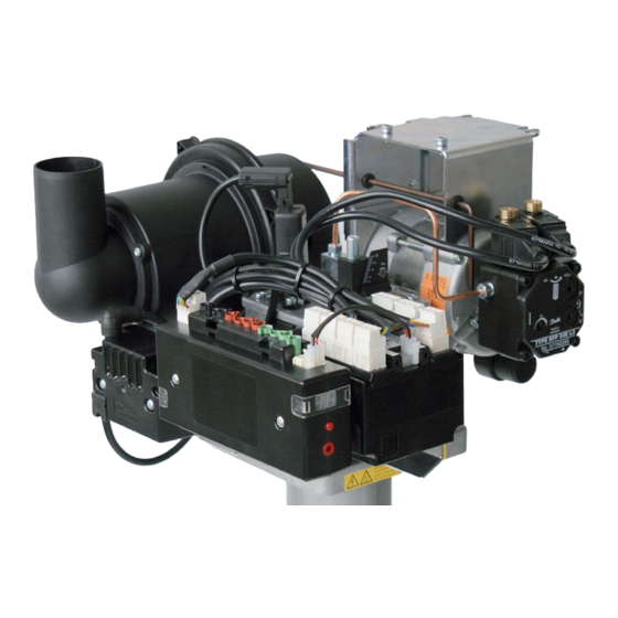
Ölbrenner /Oil burner/Brûleur fioul/Bruciatore gasolio
HLZ 45 A/BV 17/19/22/24/27/31 G1/2
Vertikal nach unten gerichtete Feuerung / Vertical down firing /
Chauffage vertical vers le bas / Riscaldamento per induzione a scorrimento verticale
Leistungsbereich/Power range/Puissance/Campo di potenza 10 - 82 kW
Technische Information, Montage- und Betriebsanleitung
Technical information, Assembly and operating instructions
Caractéristiques techniques, Instructions de montage et de service
Informazioni tecnici, istruzioni d'uso e di montaggio
BLAUBRENNER
BLUE FLAME BURNER
BRÛLEUR FLAME BLEUE
BRUCIATORE A FIAMMA BLU
BIOÖL - B10 - READY
Advertisement
Table of Contents

Related Manuals for herrmann HLZ 45 AV 17 G1


Summary of Contents for herrmann HLZ 45 AV 17 G1
- Page 1 Ölbrenner /Oil burner/Brûleur fioul/Bruciatore gasolio HLZ 45 A/BV 17/19/22/24/27/31 G1/2 Vertikal nach unten gerichtete Feuerung / Vertical down firing / Chauffage vertical vers le bas / Riscaldamento per induzione a scorrimento verticale Leistungsbereich/Power range/Puissance/Campo di potenza 10 - 82 kW Technische Information, Montage- und Betriebsanleitung Technical information, Assembly and operating instructions Caractéristiques techniques, Instructions de montage et de service...
-
Page 2: Table Of Contents
Mit einem Brenner von Herrmann hat Heizen mit Öl Tradition – und Zukunft. Heating with oil has a tradition as well as a future with a Herrmann burner. Auch künftig wird Öl als Brennstoff eine wichtige Rolle bei der Heizungsmodernisierung Oil as a fuel will play a decisive role for future heating modernization. - Page 3 Bruciatori di Herrmann – riscaldamento a olio combustibile con tradizione e futuro Avec un brûleur Herrmann le chauffage à fioul est une tradition avec avenir. Anche in futuro olio come combustibile svolgerà un ruolo importante nella modernizzazione Autant que combustible, le fioul continuera à...
-
Page 4: Technische Daten
Öldurchsatz Feuerungsleistung schwefelarm mit bis zu 10% FAME-Anteil entsprechend den Qualitäts- (USgal/h 80°H) m in kg/h in kW anforderungen der DIN 14214) HLZ 45 AV 17 G1 0,30 0,84 – 1,52 10 – 18 HLZ 45 AV 17 G1 0,35 1,10 –... -
Page 5: Verbrennungsluftgebläse
Um über den gesamten Leitungsbereich eine intensive Heizgasrezirkula- geschlossen ist, zur Einspritzdüse. Ein anderer Teilstrom fließt über Mag- tion bei hoher Stabilität der Flamme zu erreichen, wird die Verbrennungs- netventil V2, das stromlos geöffnet ist, sowie den Druckregler P1 wieder luft in einem verdrallten Freistrahl zugeführt. -
Page 6: Zündeinrichtung
onselektrode verwendet. Zur Auswertung des Signals ist innerhalb der gabe des Störcodes sowie der Entriegelung im Störfall. Zum Aufruf der je- Zündeinheit eine Schaltung integriert, die ähnlich dem optischen Flam- weiligen Menüs sowie zur Veränderung der voreingestellten Werte sind am menwächter das Vorhandensein einer Flamme über ein High/Low Signal Kommunikationsinterface (CI) ein Drehgeber sowie ein Taster vorgesehen. -
Page 7: Inbetriebnahme
Programmablauf Feuerungsautomat Elster CM 168 3.2 Elektroanschluß Bei der Elektroinstallation sind die einschlägigen VDE-, SEV-, bzw. ÖVE- Wärmeanforderung Stufe 1 Vorschriften sowie Forderungen der örtlichen Stromversorgungsunterneh- Wärmeanforderung Stufe 2 men zu beachten. Netzanschluss 230 V~ 50 Hz 10 A. Der Brenner muss Flammensignal Ölvorwärmer an die Norm-Steckverbindungen des Kessels angeschlossen werden;... -
Page 8: Brennereinstellung
Dimensionierungsdiagramm für Saugleitungen, Dimension Ø 4/6 mm • Wenn der höchste Punkt des Ölstandes im Öltank über der Ölpumpe Anwendungsbereich: 1-10 l/h, Öltemperatur: 0-10 °C (Aussentank) des Brenners liegt, muss an der höchsten Stelle der Ölleitung, so nahe [l/h] [m/s] wie möglich beim Öltank, ein Anti-Heber-Ventil eingebaut werden. -
Page 9: Wartung Des Brenners
Messung des CO ² -Gehalts sowie eine Bestimmung der Rußzahl unum- 4. Wartung des Brenners gänglich. Wir empfehlen in beiden Laststufen einen Betrieb des Brenners bei einem CO ² -Gehalt im Bereich von 12,5 - 13,0%. Die Rußzahl darf da- Im Wartungsfall die Klemmschraube am Flansch mit dem Innensechs- bei im Betrieb einen Wert von Rz=0,5 nicht übersteigen. -
Page 10: Grundeinstelltabelle
1./2. Stufe Gebläse Öldüse 1. Stufe 2. Stufe Luftdüse Brennerrohr USgal/h 80° H kg/h kg/h Ø mm Ø mm HLZ 45 AV 17 G1 HRG 134 0,30 0,84 1,52 17,50 HLZ 45 AV 17 G1 HRG 134 0,35 1,10 1,69 17,50... - Page 11 Gebläse- Gebläse- Gebläse- Gebläse- Rezirkulationsspalt Abstand Rezirkulations- drehzahl drehzahl druck druck Öldruck Öldruck (Einstellskala Luftdüse- rohr 1. Stufe 2. Stufe 1. Stufe 2. Stufe 1. Stufe 2. Stufe tatsächliche Weite) Öldüse Ø [mm] x l [mm] mbar mbar 80 x 160 3.780 5.640 10,9...
-
Page 12: Explosionszeichnung Mit Ersatzteilliste
7. Explosionszeichnung mit Ersatzteilliste... - Page 13 Mischkopf MB 819,0 komplett 10015.00138 Mischkopf MB 822,0 komplett 10015.00139 Mischkopf MB 824,0 komplett 10015.00140 Wichtig: Bitte verwenden Sie nur Original Herrmann-Ersatzteile, andernfalls erlischt Ihre Luftdüse MB 817,5 10015.00056 Luftdüse MB 819,0 10015.00006 Garantie (siehe Garantiebestimmungen). Alle Ersatzteilbestellungen mit Benen- Luftdüse MB 822,0 10015.00007...
-
Page 14: Fehlerdiagnose
8. Fehlerdiagnose Feststellung Ursache Behebung 1. Ölfeuerungsautomat/Kommunikationsinterface − Ausgegebene Fehlercodes „Time out“ Gebläsedrehzahl Verkabelung zwischen Feuerungsautomat Kabel austauschen und Gebläse defekt Gebläse defekt Gebläse austauschen Keine Flammenbildung während der Ölversorgung: Zu hoher Unterdruck in der Ölversorgung gemäß Spezifikation ausführen Sicherheitszeit Saugleitung Feuerraumdruck zu hoch Abgassystem überprüfen... - Page 15 Ölpumpe Öldruck schwankt, hohes Betriebsgeräusch, Saugleitung undicht (Lufteintrag) Ölversorgung prüfen Öldruck baut sich nicht auf Ölversorgung nicht gemäß Spezifikation Ölversorgung prüfen Saugleitung nicht entlüftet Saugleitung entlüften Ölabsperrhahn geschlossen Ölabsperrhahn öffnen Kupplung defekt Kupplung austauschen Ölpumpenfilter verschmutzt Ölpumpenfilter austauschen Vorfilter verschmutzt Vorfilter austauschen Getriebsatz Ölpumpe defekt Ölpumpe austauschen...
-
Page 16: Brennerabmessungen
9. Brennerabmessungen 215 Gebläse HGR 134 159 Gebläse HGR 134 233 Gebläse RG 148 171 Gebläse RG 148 Ø 80 x Ø 80 x 160 Ø 80 x Ø 100 x 150 132 Gebläse HGR 134 139 Gebläse RG 148... -
Page 17: Zubehör
11. Kundenservice wird hierzu über einen Interfaceadapter an die Für technische Fragen zum Brenner sowie zur Bestellung von Ersatzteilen USB-Schnittstelle wenden Sie sich bitte an unseren Kundenservice. PC angeschlossen. Herrmann GmbH u. Co. KG Tel.: 0049-7151-98928-0, Fax.: 0049-7151-98928-49 Email: info@herrmann-burners.de... -
Page 18: Menüstruktur Kommunikationsinterface
Menustruktur Kommunikationsinterface Error Status / Fehlerzustand Betriebszustand Bei der Anzeige Betriebszustandes des Feuerungsautomaten wird mit Hilfe der beiden Punkte die aktuelle Laststufe dargestellt. Ein Punkt leuchtet = Laststufe 1 Beide Punkte leuchten = Laststufe 2 Betriebsanzeige Blinkt im Wechsel Taster 3s drücken Im Menü... - Page 19 Parameter Error History / Fehlerhistorie (”Kalteinstellung”) Liegt externe Wärme- anforderungssignal vor, werden kurzzeitig Striche Das P-Menü ist nur zugäng- angezeigt und dann lich,wenn kein externes Wärmen- zurückgesprungen. anforderungs- signal vorliegt. Innerhalb des P-Menüs wird eine Wärme- anforderung unterdrückt. Ist in der Fehlerhistorie unter der jeweiligen Wird ein Parameter oder dessen Fehlernummer kein Fehler eingetragen, Grenzen vom Feuerungsautomat...
-
Page 20: Technical Data
DIN SPEC 51603-6, heating oil EL, low sulphur, with up to 10% portion (US gal/h 80°H) m in kg/h in kW of FAME, corresponding to the quality requirements of DIN 14214) HLZ 45 AV 17 G1 0,30 0,84 – 1,52 10 – 18 HLZ 45 AV 17 G1 0,35 1,10 –... -
Page 21: Combustion Air Blower
In order to achieve an intensive recirculation of flue gas over the entire Another partial flows back again through the current-less open solenoid performance range in combination with a high stability of the flame the valve V2 and the pressure regulator P1 to the suction side of the gear combustion air is supplied in a swirled jet. -
Page 22: Ignition Device
For evaluation of the signal a circuit element, similar to the optical flame normal occurrences. A rotary encoder and a button are visible at the com- detector, is integrated inside the ignition unit that displays the presence munication interface to call up the respective menu and to alter the pre- of a flame through a high/low signal. -
Page 23: Initial Operation
Program flow of Elster CM 168 control box; 3.2 Electricity supply While carrying out electrical installations you must observe the relevant Heat demand stage 1 provisions of VDE (Association of German Electro-technical Engineers), Heat demand stage 2 SEV (Swiss Association of Electro-technical Engineers) or ÖVE (Austrian Flame signal Association of Electro-technical Engineers). -
Page 24: Burner Adjustment
Diagram of dimensions for suction pipes, dimension Ø 4/6 mm • If the highest level of the oil in the tank is above the oil pump of the bur- Range of application: 1-10 liters/h, oil temperature: 0-10 °C (outdoor tank) ner you must install a solenoid valve at the highest point of the oil pipe, [l/h] [m/s]... -
Page 25: Maintenance Of The Burner
necessary to carry out the measuring of the CO content, as well as 4. Maintenance of the burner determining the soot number. We would therefore recommend for both on-load stages to run the burner with a CO content within the range When maintenance is required, loosen the clamping screw at the flange 12.5%-13.0%. -
Page 26: Basic Adjustment Table
Oil nozzle 1st level 2nd level Air nozzle Burner tube USgal/h 80° H kg/h kg/h Ø mm Ø mm HLZ 45 AV 17 G1 HRG 134 0,30 0,84 1,52 17,50 HLZ 45 AV 17 G1 HRG 134 0,35 1,10 1,69... - Page 27 Speed Speed Blower Blower Re-circulation gap Distance Re-circulation of blower, of blower, pressure, pressure, pressure pressure (Adjusting dial of oil > tube 1st level 2nd level 1st level 2nd level 1st level 2nd level of actual width) air nozzle Ø [mm] x l [mm] mbar mbar 80 x 160...
-
Page 28: Expanded View With Spare Parts List
7. Expanded view with spare parts list... - Page 29 Mixing head, MB 824.0, complete 10015.00140 Important: Air nozzle, MB 817.5 10015.00056 Please only use original Herrmann spare parts, since otherwise the guarantee Air nozzle, MB 819.0 10015.00006 is null and void (see guarantee conditions). When ordering spare parts, please Air nozzle, MB 822.0 10015.00007...
-
Page 30: Malfunction Diagnosis
8. Malfunction diagnosis Diagnosis Cause Rectification 1. Control box/Communication interface − Issued error codes 3: Time-out blower speed Electrical wiring between oil firing unit and Exchange the cables blower is defective Defective blower Exchange the blower 4: No formation of flame during the safety time Oil supply: Excessive low pressure in the Check oil supply in accordance with the suction line specification... - Page 31 5. Oil pump Oil pressure is fluctuating, heavy operating Leaking suction line (admission of air) Check oil supply noise, oil pressure is not established Oil supply not in accordance with the Check oil supply specifications Suction line is not de-aerated De-aerate the suction line Oil stop-cock is locked Open the oil stop-cock...
-
Page 32: Dimensions Of The Burner
9. Dimensions of the burner 215 Blower HGR 134 159 Blower HGR 134 233 Blower RG 148 171 Blower RG 148 Ø 80 x Ø 80 x 160 Ø 80 x Ø 100 x 150 Ø 80 x Ø 120 x 190 132 Blower HGR 134 139 Blower RG 148... -
Page 33: Accessories
For further information on the burner and for ordering spare parts please do not hesitate to contact our Customer Service Department at: Herrmann GmbH u. Co. KG Phone: 00 49 7151 98928-0, Fax: 00 49 7151 98928-49 Email: info@herrmann-burners.de... -
Page 34: Menustructure Of Communication Interface
Menu structure of communication interface Error status Operating state By means of both points the current power stage is shown at the display of the firing units state of operation. One point is lighting = power stage 1 System panel Both points are lighting = power stage 2 Flashes in turn Push button 3s... - Page 35 Parameter Error History (”Cold adjustment”) If an external heat request signal exists dashes are briefly displayed and then The P menu is only returned. available if no external request for a heat signal exists. A heat request is suppressed within the P menu ..
-
Page 36: Données Techniques
51603-6, fioul domestique pauvre en soufre jusqu’à 10% de part FAME, (USgal/h 80°H) m en kg/h chauffage QF en kW conformément aux exigences qualitatives de DIN 14214) HLZ 45 AV 17 G1 0,30 0,84 – 1,52 10 – 18 HLZ 45 AV 17 G1 0,35 1,10 –... -
Page 37: Ventilateur À Air De Combustion
Pour parvenir à une recirculation intense des gaz brûlés sur toute la plage mée lorsque hors tension. Une autre partie du flux traverse l’élec trovanne de puissance tout en conservant une haute stabilité de flamme, on injecte V2, ouverte lorsque hors tension, ainsi que le régulateur de pression P1, puis l’air de combustion sous la forme d’un jet libre torsadé. -
Page 38: Dispositif D'allumage
d’électrode ionisante. Pour analyser le signal, un circuit a été intégré dans service du brûleur, d’éditer le code d’un dérangement ainsi que de déver- l’unité d’allumage ; un peu comme un contrôleur visuel de flamme, il sig- rouiller en cas de dérangement. Pour appeler les menus respectifs ainsi nale la présence d’une flamme via un signal High/Low. -
Page 39: Mise En Service
3.2 Branchement électrique Au moment d’installer les circuits électriques, il faut respecter les directi- ves VDE, SEV et ÖVE applicables ainsi que les exigences publiées par les Demande de chaleur allure 1 Demande de chaleur allure 2 compagnies locales distributrices d’électricité. Raccordement au secteur Signale de flame 230 V~ 50 Hz 10 A. -
Page 40: Réglage Du Brûleur
Diagramme de dimensionnement pour conduites d’aspiration, dimension Ø 4/6 mm • Si le niveau de fioul le plus élevé dans la citerne se trouve au dessus de Domaine d’application : 1-10 l/h, température du fioul : 0-10 °C (citerne à l’extérieur) la pompe à... -
Page 41: Maintenance Du Brûleur
suie. Nous recommandons, aux deux niveaux de charge, d’exploiter le 4. Maintenance du brûleur brûleur avec une teneur en CO ² comprise entre 12,5 et 13,0% vol. En service, l’indice de noircissement ne doit pas dépasser la valeur R =0,5. En cas de maintenance, desserrez la vis de bridage située sur la bride à... -
Page 42: Tableau Des Réglages De Base
Soufflerie à fioul 1er niveau 2e niveau d’air foyer USgal/h 80° H kg/h kg/h Ø mm Ø mm HLZ 45 AV 17 G1 HRG 134 0,30 0,84 1,52 17,50 HLZ 45 AV 17 G1 HRG 134 0,35 1,10 1,69 17,50... - Page 43 Vitesse Vitesse Pression Pression Pression Pression Fente de recirculation Écart Tube de soufflerie soufflerie soufflerie soufflerie fiou fiou (échelle de réglage gicleur air / recirculation 1er niveau 2e niveau 1er niveau 2e niveau 1er niveau 2e niveau de l’ouverture réelle) gicleur de fioul Ø...
-
Page 44: Vue Éclatée Avec Liste Des Pièces De Rechange
7. Vue éclatée avec liste des pièces de rechange... - Page 45 Tête mélangeuse MB 822,0 complète 10015.00139 Tête mélangeuse MB 824,0 complète 10015.00140 Important: Prière d’utiliser exclusivement les pièces de rechange de marque Herrmann, Gicleur d’air MB 817,5 10015.00056 sinon la garantie n’est pas valable (Cf. conditions de garantie). Gicleur d’air MB 819,0 10015.00006...
-
Page 46: Diagnostic Des Erreurs
8. Diagnostic des erreurs Constat Cause Remède 1. Coffret de contrôle/Interface de communication − Codes de défaut émis 3: Time out vitesse ventilateur Câblage défectueux entre l’automate de Remplacer le câble chauffage et la ventilateur Ventilateur défectueuse Remplacer la ventilateur 4: Aucune formation de flamme pendant le Alimentation en fioul : dépression excessive Réaliser l’alimentation en fioul conformément... - Page 47 5. Pompe à fioul La pression du fioul varie, bruit de fonctionne- Conduite d’aspiration pas étanche Vérifier l’alimentation en fioul ment élevé, le fioul ne monte pas en pression (aspiration d’air) Alimentation en fioul non-conforme à la Vérifier l’alimentation en fioul spécification Conduite d'aspiration pas dégazée Dégazer la conduite de gaz...
-
Page 48: Dimensions Du Brûleur
9. Dimensions du brûleur 215 Ventilateur HGR 134 159 Ventilateur HGR 134 233 Ventilateur RG 148 171 Ventilateur RG 148 Ø 80 x Ø 80 x 160 Ø 80 x Ø 100 x 150 Ø 80 x Ø 120 x 190 132 Ventilateur HGR 134 139 Ventilateur RG 148... -
Page 49: Accessoires
à l’interface USB du PC Questions techniques sur le brûleur et commande de pièces de rechange: veuillez s.v.p. contacter notre service après-vente. via un adaptateur d’in- terface. Herrmann GmbH u. Co. KG Tél.: 0049-7151-98928-0, Fax: 0049-7151-98928-49 Courriel: info@herrmann-burners.de... -
Page 50: Structure Du Menu De L'interface De Communication
Structure du menu de l’interface de communication Error Status / État de défaut Mode de fonctionnement Concernant l’affichage de l’état de service dans lequel se trouve le coffret de contrôle, les deux points servent à représenter le niveau de charge actuel. Affichage de service Un point allumé... - Page 51 Paramètres Error History / Historique des défauts (« Réglage à froid ») En présence d’un signal de demande de chaleur, tous les trait s’affichent Le menu P n’est accessible brièvement puis s’éteignent qu’en l’ab- sence d’un signal successivement. extérieur de demande de chaleur. Dans le menu P, une demande de chaleur est...
-
Page 52: Dati Tecnici
(USgal/h 80°H) m in kg/h in kW di zolfo fino a una quota di 10% FAME. Come l’ho propone la conformita HLZ 45 AV 17 G1 0,30 0,84 – 1,52 10 – 18 DIN 14214. HLZ 45 AV 17 G1 0,35 1,10 –... -
Page 53: Ventilatore Dell'aria Per La Combustione
Per ottenere un intenso ricircolo dei gas combusti con una fiamma molto sta- V1 che è chiusa senza corrente all’ugello d’iniezione. L’altra parte del com- bile in tutto il condotto l’aria per la combustione viene portata in forma di un bustibile ritorna attraverso la valvola magnetica V2 che è... -
Page 54: Impianto D'accensione
viene usato come elettrodo d’ionizzazione. Per analisi del segnale l’impi- Per accendere al menu corrispondente e per la modifica dei valori presta- anto è dotato di un collegamento che simile al pirostato ottico indica la biliti ci sono previsti un trasduttore di velocità e un tasto dell’interfaccia di presenza della fiamma usando il segnale High/Low. -
Page 55: Messa In Funzione
Svolgimento del programma dell’impianto di combustione Elster CM 168 3.2 Collegamento elettrico In caso d'una installazione elettrica si deve rispettare le regole VDE, SEV o ÖVE, come pure le esigenze delle imprese di fornitura di energia elet- trica. L’allacciamento alla rete 230 V~ 50 Hz 10 A. Il bruciatore deve essere allacciato ad un connettore ad innesto di standard della caldaia, vuol dire secondo la norma DIN 4791:1985-09 tramite un connettore Euro a 7 poli ed un connettore Euro a 4 poli. -
Page 56: Impostazioni Del Bruciatore
Diagramma di dimensioni per condotti d’aspirazione, dimensione del diametro 4/6 mm • Se il punto più alto del livello del combustibile nel serbatoio sta sopra Campo d’impiego: 1-10 l/h, temperatura d’olio: 0-10°C (serbatoio esterno). la pompa del combustibile del bruciatore ci vuole una valvola magnetica [l/h] [m/s] montata al punto più... -
Page 57: Manutenzione Del Bruciatore
una misurazione del contenuto di CO ² e un’analisi della quantità di fulig- 4. Manutenzione del bruciatore gine durante la messa in funzione del bruciatore. Vi consigliamo un im- piego del bruciatore in entrambi stadi di carico con il contenuto di CO ² Per i lavori di manutenzione allentare la vite di serraggio sulla flangia per tra 12,5 –... -
Page 58: Tabella D'impostazioni Di Base
2° stadio 1°/2°stadio Ventilatore combustibile 1° stadio 2° stadio dell’aria bruciatore USgal/h 80° H kg/h kg/h Ø mm Ø mm HLZ 45 AV 17 G1 HRG 134 0,30 0,84 1,52 17,50 HLZ 45 AV 17 G1 HRG 134 0,35 1,10 1,69... - Page 59 N° di giri N° di giri Pressione Pressione Pressione Pressione Fessura di ricircolo Intervallo ugello Tubo di ventilatore ventilatore ventilatore ventilatore combustibile combustibile (scala di regolazione) dell’aria-ugello ricircolo 1° stadio 2° stadio 1° stadio 2° stadio 1° stadio 2° stadio larghezza reale del combustibile Ø...
-
Page 60: Disegno Esploso Con Lista Parti Di Ricambio
7. Disegno esploso con lista parti di ricambio... - Page 61 Importante: Ugello dell’aria MB 819,0 10015.00006 Si prega di usare soltanto i parti di ricambio originali di Herrmann, altrimenti la ga- Ugello dell’aria MB 822,0 10015.00007 ranzia si estinge (vedi condizioni di garanzia). Il modulo d'ordine dei parti di ricambio Ugello dell’aria MB 824,0...
-
Page 62: Diagnostica Errore
8. Diagnostica errore Segnalazione Possibile causa Rimedio 1. Impianto di combustionne/Interfaccia di comunicazione – indicazione codici errori “Time out” Numero di giri ventilatore Cablaggio fra impianto di combustione e Cambiare il cavoCambiare ventilatore è difettoso Ventilatore è difettoso Cambiare il ventilatore La fiamma non si accende durante Alimentazione combustibile: la sottopressione Eseguire l’alimentazione del combustibile... - Page 63 Pompa del combustibile La pressione del combustibile varia, rumore Il condotto d’aspirazione non tiene (entrata aria) Controllare l’alimentazione del combustibile rotolante,la pressione del combustibile L’alimentazione del combustibile non corrisponde Controllare l’alimentazione del combustibile non sorge alle specificazioni Il condotto dell’aria non è disaerato Disaerare il condotto dell’aria Il rubinetto di chiusura del combustibile è...
-
Page 64: Dimensioni Del Bruciatore
9. Dimensioni del bruciatore 215 Ventilatore HGR 134 159 Ventilatore HGR 134 233 Ventilatore RG 148 171 Ventilatore RG 148 Ø 80 x Ø 80 x 160 Ø 80 x Ø 100 x 150 Ø 80 x Ø 120 x 190 132 Ventilatore HGR 134 139 Ventilatore RG 148... -
Page 65: Accessori
11. Servizio clienti all’interfaccia USB del Per qualsiasi informazione tecnica sul bruciatore oppure per l’ordine dei pezzi di ricambio si prega di contattare il nostro servizio clienti. Herrmann GmbH u. Co. KG Telefono: 0049-7151-98928-0, Fax.: 0049-7151-98928-49 Email: info@herrmann-burners.de... -
Page 66: Struttura Del Menu Interfaccia Di Comunicazione
Struttura del menu Interfaccia di comunicazione Stato errore Stato d’esercizio Il display dello stato d’esercizio dell’impianto di combustione visualizza lo stadio di carico attuale per mezzo di entrambi punti. Un punto è acceso = stadio di carico 1 Entrambi punti sono accesi = stadio di carico 2 Indicazione d’esercizio Lampeggia in mod o alternato Premere il tasto per 3 s... - Page 67 Parametri Storia d’errori (“impostazione a freddo”) Se c’è un segnale di richiesta del calore esterno sarà visualizzata Il menu P è solo accessi- brevemente una barra dopo bile, quando non c’è un segnale di di che si salterà all’indietro. richiesta del calore esterno.
- Page 68 Herrmann GmbH u. Co. KG Liststraße 8 D-71336 Waiblingen Tel. +49 (0) 71 51-9 89 28-0 Fax +49 (0)7151-9 89 28-49 E-Mail info@herrmann-burners.de Internet www.herrmann-burners.de...
Need help?
Do you have a question about the HLZ 45 AV 17 G1 and is the answer not in the manual?
Questions and answers