Table of Contents
Advertisement
Operation
Manual
INVERTER-DRIVEN
MULTI-SPLIT SYSTEM
HEAT PUMP
AIR CONDITIONERS
Type
Model
TIWM006B21S
TIWM008B21S
TIWM012B21S
Wall Mount
TIWM015B21S
TIWM018B21S
TIWM024B21S
TIWM030B21S
IMPORTANT:
READ AND UNDERSTAND
THIS MANUAL BEFORE
USING THIS HEAT PUMP
AIR CONDITIONER.
KEEP THIS MANUAL FOR
FUTURE REFERENCE.
P5417053
Advertisement
Table of Contents

Related Manuals for Johnson Controls TIWM006B21S


Summary of Contents for Johnson Controls TIWM006B21S
- Page 1 Operation Manual INVERTER-DRIVEN MULTI-SPLIT SYSTEM HEAT PUMP AIR CONDITIONERS Type Model TIWM006B21S TIWM008B21S TIWM012B21S Wall Mount TIWM015B21S TIWM018B21S TIWM024B21S TIWM030B21S IMPORTANT: READ AND UNDERSTAND THIS MANUAL BEFORE USING THIS HEAT PUMP AIR CONDITIONER. KEEP THIS MANUAL FOR FUTURE REFERENCE. P5417053...
- Page 3 Important Notice Johnson Controls Inc. pursues a policy of continuing improvement in design and performance in its products. As such, Johnson Controls Inc. reserves the right to make changes at any time without prior notice. Johnson Controls Inc. cannot anticipate every possible circumstance that might involve a potential hazard.
-
Page 4: Table Of Contents
......................6 4. Name of Parts and Indications for Safety Consideration ................7 4.1 Wall Mount Type .............................7 4.1.1 TIWM006B21S, TIWM008B21S and TIWM012B21S ..............7 4.1.2 TIWM015B21S, TIWM018B21S, TIWM024B21S and TIWM030B21S ........8 4.2 Wired Controller (CIW01) ........................10 4.3 Wireless Controller (CIR01) ......................... 11 5. -
Page 5: Introduction
Introduction Read this manual carefully before working with this product. Keep this information with the product. Ask them to keep this manual with the air conditioning unit. (Refrigerant Piping Work) (Electrical Wiring Work) (Ref. Charge Work) (Test Run) (User) manual for the outdoor unit. controller module. - Page 6 This unit is the pressurized system. Never loosen threaded joints while the system is under pressure and never open pressurized system parts. Johnson Controls will not assume any liability for injuries or damage caused by not following steps outlined or May create hazards which could result in death, serious injury, equipment damage or property damage;...
- Page 7 Operation electrical components. electrical shock. equipment (space heaters). It may interfere with the combustion process in these units. pockets that can make people uncomfortable. refrigerant gases that happen to come into contact with any heat source can become toxic on contact which can cause suffocation in the immediate area.
- Page 8 Repair / Relocation Others result in damage to internal components with severe or fatal electrical shock. contractor. Serious or fatal injury can occur. may cause falling or injury. About Wireless Controller 1. Never use new and used batteries together. 2. Never use the different types of batteries (for example manganese battery and alkaline battery) together.
-
Page 9: Before Operation
Before Operation NOTICE Power is turned on. Apply power to the outdoor unit(s) at least 12 hours prior to operation of the system for preheating of the compressor oil. Make sure that the outdoor unit is not covered with snow or ice. If it is, remove it by using hot water that is approximately 122 F (50 If the water temperature is higher than 122 F (50... - Page 10 Air Outlet Angle Louver Angle Louver Angle Air Outlet Angle Unit Type Unit Type TIWM006B21S ~ 012B21S TIWM006B21S ~ 012B21S TIWM015B21S ~ 030B21S TIWM015B21S ~ 030B21S (Refer to Sections 5.1.6 and 5.2.5 for details.) (Refer to Sections 5.1.6 and 5.2.5 for details.) wider than “MED”.
-
Page 11: Name Of Parts And Indications For Safety Consideration
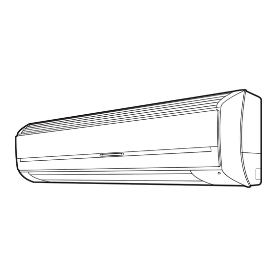
Name of Parts and Indications for Safety Consideration Read and understand this manual before using the indoor unit. Wall Mount Type 4.1.1 TIWM006B21S, TIWM008B21S and TIWM012B21S WARNING Label Air Inlet Indoor Unit Electrical Hazard Located on electrical box cover. Louver... -
Page 12: Tiwm015B21S, Tiwm018B21S, Tiwm024B21S And Tiwm030B21S
4.1.2 TIWM015B21S, TIWM018B21S, TIWM024B21S and TIWM030B21S WARNING Label Air Inlet Indoor Unit Indicator Louver Electrical Hazard Located on electrical box cover. Front Cover Panel Flat Panel attached inside.) WARNING Label Receiver Air Outlet Wired Controller or Wireless Controller (Option) Location of Indoor Unit Model Indicator Indication It is indicated on the unit nameplate... - Page 13 NOTICE connected, restrictions are in place limiting operation of indoor units with a single wireless controller or utilize wired and wireless controllers together. Contact your distributor or contractor for details. timer settings is indicated on the wired controller only. P5417053-rev.1...
-
Page 14: Wired Controller (Ciw01)
Wired Controller (CIW01) the unit according to the manual for that controller. The example below references the control panel and all adjustable settings. The wired controller display may be Display Part different during actual operation. Fan Speed Indicator Schedule Timer Indicator is displayed when the schedule timer function is set. -
Page 15: Wireless Controller (Cir01)
Wireless Controller (CIR01) This controller is used to send commands about operation mode timer settings and so on, to the indoor unit. commands to indoor unit. The effective transmission range limit is approximately 19.7ft (6m). The effective distance for transmitting shortens if the transmitter is not perpendicular to the receiver or if there is other electronic interference in the room. -
Page 16: Operation Method
Operation Method Wired Controller (CIW01) Meeting Room FLTR MODE SPEED LOUV. TEMP 5.1.1 Basic Operation Avoid COOL Motion Sensor ON LOUV. Adj. Menu On/Off Back/Help ECO By pressing “ ”or “ ”, the icon “ ” will move between “MODE”, “SPEED”, Menu “LOUV.”... - Page 17 Function * Cooling Operation: To decrease the room temperature. * Heating Operation: To increase the room temperature. * Dry Operation: To decrease the humidity in the room. Dry operation may not be performed properly if there are other heat sources which exceed the capacity of the unit.
-
Page 18: Temperature Setting
5.1.3 Temperature Setting Press “ ” or “ ” and select “TEMP”. Menu Back/Help By pressing “ ”, the temperature is Menu By pressing “ ”, the temperature is Back/Help In case the optional function “Automatic Reset of Setting Temperature” is set: Even if changing the setting temperature on the wired controller, it automatically returns to the temperature set by “Automatic Reset Temperature”... -
Page 19: Operation
5.1.5 Operation Press “ The RUN indicator is turned ON and the operation will start. Operation On/Off Start Temperature/Air Flow Setting required, refer to Sections 5.1.2 to 5.1.4. Press “ operation will stop. Operation On/Off Stop The indoor unit fan may continue to operate for up to two minutes following the heating cycle to dissipate residual heat from the indoor unit. -
Page 20: Louver Swing Direction
Menu Back/Help LCD Indication Auto Swing : Auto-swing operation will be started. At this time, the louver animation will swing repeatedly on LCD. TIWM006B21S TIWM012B21S Step LCD Indication Louver Angle Approx. 15 Approx. 22 Approx. 28 Approx. 35 Approx. - Page 21 Adjust the vertical blade by hand as shown below. Vertical Blade Louver Vertical Blade Louver TIWM006B21S TIWM012B21S TIWM015B21S ~ TIWM030B21S The swing louver is stopped and moved by controlling the wired controller. The louver will automatically close when the unit is stopped from the wired controller.
-
Page 22: Setback Operation
Contact your distributor or contractor for details. operation, during auto mode both cooling setpoint and heating setpoint can be selected. are as follows. Cooling mode changes to heating mode when the indoor temperature is heating setpoint -2 Heating mode changes to cooling mode when the indoor temperature is cooling setpoint +2 If the temperature for changing modes requires to be changed, NOTE:... -
Page 23: Wireless Controller (Cir01)
Wireless Controller (CIR01) Function * Cooling Mode (COOL): To decrease the room temperature. * Heating Mode (HEAT): To increase the room temperature. * Dry Mode (DRY): To decrease the humidity in the room. Turn ON the power supply. Apply power to unit(s) for approximately 12 hours before operation Before in order to preheat the compressor. - Page 24 RUN indicator (orange) on indoor unit is turned ON and the beep sound is heard. The operation is started. Beep NOTE: (TIWM015B21S (TIWM006B21S Do not press “On ” and “Off ” switches to TIWM030B21S) to TIWM012B21S) repeatedly (within 3 seconds).
- Page 25 NOTE When the wireless controller is pressed, the transmitting indicator “ the wireless controller and the beep sound is heard from the indoor unit. Point the transmitter towards the receiver and press “Temp” switch to set the temperature. By pressing “ ”, the temperature is increased by Tempera- By pressing “...
- Page 26 note that there is quite temperature difference between cooling and heating operation when using this function. and contractor for details. Function NOTE switches cooling and heating based on the set temperature. heating operation, the operation tends to be stopped by activation of the protection devices, The cooling operation is performed when the inlet etc.
- Page 27 ON and the beep sound is heard. The operation is started. Beep NOTE: (TIWM015B21S (TIWM006B21S Do not press “On ” and “Off ” switches to TIWM030B21S) to TIWM012B21S) repeatedly (within 3 seconds). If the switch is...
-
Page 28: Timer Setting
5.2.4 Timer Setting Function This function is used to start or stop unit operation at a pre-set time. On Timer The operation is started beyond the set time. Off Timer : The operation is stopped beyond the set time. Press “On Timer ”... -
Page 29: Louver Swing Direction
2 Step 3 Step 4 Step 5 Step 6 Step 7 Step Swing The louver angle is set to 1 step at “HIGH” in the cooling mode. By pressing the “LOUVER” switch, the louver direction will be changed as follows. TIWM006B21S to TIWM012B21S Step LCD Indication Approx. 15 Approx. 22 Approx. - Page 30 Adjust the vertical blade by hand as shown below. Vertical Blade Louver Vertical Blade Louver TIWM006B21S ~ TIWM012B21S TIWM015B21S ~ TIWM030B21S The swing louver is stopped and moved by controlling the wireless controller. The louver will automatically close when the unit is stopped from the wireless controller. Louver...
-
Page 31: Emergency Operation
When the wireless controller battery power dies, The operation is as follows. the emergency operation switch on the unit is used. Louver Angle: Horizontal TIWM006B21S ~ TIWM012B21S TIWM015B21S ~ TIWM030B21S Press the emergency operation switch. Press the emergency operation switch with a non- metallic tool, etc. -
Page 32: Other Indications
Operation Stoppage during Defrosting Operation (for FILTER/DEF FILTER/DEF Unit Only) when pressing “Off ” switch during the (TIWM015B21S (TIWM006B21S defrosting. to TIWM030B21S) to TIWM012B21S) The figure shows for TIWM015B21S to TIWM030B21S. operation. Filter Sign This occurs when the operation time has Filter accumulated 200 hours. -
Page 33: Identifying Indoor Units Installed Side By Side
5.2.8 Identifying Indoor Units Installed Side by Side This function is used when operating several receivers or indoor units side by side, to prevent a malfunction because incorrect signals were received from the wireless controllers used in other areas. Only the communication between the paired setting is possible, and four pairs (A, B, C, D) are available. cannot receive signals from wireless controller set as B, C or D. -
Page 34: Handling Wireless Controller
5.2.9 Handling Wireless Controller The distance for transmitting is approximately 16.4ft (5m) maximum. (The distance for transmitting shortens if the transmitting angle is not vertical to the receiver or if there is other electronic interference in the room.) Maintain a minimum of 3.3ft (1m) distance between the Direct Line: 16.4ft (5m) The figure shows for TIWM015B21S to 030B21S. -
Page 35: Automatic Control
Automatic Control This air conditioner automatically starts the following operations according to the indoor conditions. The system is equipped with the following functions. The compressor remains off for at least three minutes once it has stopped. If the system is started within approximately three minutes after it has stopped, the RUN indicator is activated. -
Page 36: Maintenance
SPEED LOUV. TEMP Avoid COOL Motion Sensor ON LOUV. Adj. Menu On/Off Back/Help ECO CIR01 Filter Sign (The yellow lamp is turned ON.) To reset TIWM006B21S to TIWM012B21S Filter Sign (The yellow lamp is turned ON.) TIWM015B21S to TIWM030B21S P5417053-rev.1... - Page 37 indicators in the proper position. may cause malfunction of the indoor unit. CIW01 Release the two (2) catches and pull the air NOTE been set, the indication “ ” appears and “Setting Disabled” will be displayed. Press “Menu”. and press “OK”. Menu 15:10(Fri) Simple Timer...
- Page 38 NOTICE attention that the parts around the air outlet (louver, guide, etc.) may be damaged if an excessive force is applied. TIWM006B21S to TIWM012B21S Insert both support arms into the recessed After the right arm shaft is expanded outward openings and close the lid. Check that the and shafts are removed from the front panel, pull expanded outward.
-
Page 39: Maintenance Prior To And After Use
Maintenance Prior to and After Use Prior to Use Remove any obstacles around the air inlet grilles and the air outlet of the indoor unit and outdoor unit. After Use Replacing Batteries (CIR01) Under the normal use, battery life should be about 1 year (in the case of alkaline batteries). Replace the batteries if the following phenomenon occurs: The transmission distance between the wireless controller and the receiver gets shorter for operation or fan speed adjustment. -
Page 40: Troubleshooting
Troubleshooting This is Not Abnormal Phenomenon Cause and Action All indication lamps on the The micro-computer is activated to protect the wired controller are turned device from electromagnetic waves. Restart the operation. Operation Stopped Restart the operation. If the instantaneous power failure is within two seconds, the operation restarts automatically. -
Page 41: Before Contact
Before Contact Refer to the information below before contacting a contractor. Trouble Check Point Action Check that the main power Turn ON the main power source for the air source is turned ON. conditioner. Check that the fuse is not Operation Unavailable Replace the fuse or reset the circuit breaker. -
Page 42: Contact Distributor
Contact Distributor If problem still remains even after checking previous issues or other problems not mentioned in the previous issues occur, stop using the product and contact your distributor or contractor. If an abnormality such as a burnt odor or something similar occurs, stop the operation and turn OFF the main power source immediately. -
Page 43: Alarm Code
Alarm Code Code Category Content of Abnormality Code Category Content of Abnormality Indoor Unit Activation of Protection Device Incorrect Setting of Indoor Unit No. Activation of Protection Device Outdoor Unit System Incorrect Indoor Unit Combination (High Pressure Cut) Operational Irregularities between Problem with Protective Pickup Circuit Indoor and Outdoor in Outdoor Unit... - Page 44 © 2017 Johnson Controls, Inc. P5417053-rev.1 Code No. LIT-12012617 Revised April 2018...
Need help?
Do you have a question about the TIWM006B21S and is the answer not in the manual?
Questions and answers