Advertisement
Quick Links
Advertisement

Related Manuals for Smart Caregiver TL-2015R2


Summary of Contents for Smart Caregiver TL-2015R2
- Page 1 Installation and Use Instructions TL-2015R2 Wireless Central Monitor and Nurse Call Paging System Optional Accessories 433-PGD 433-NC Caegiver Pocket Pager with Wireless Nurse Call Button LCD Display S M A R T C A R E G I V E R C O R P O R AT I O N Tel: (800) 650-3637 www.smartcaregivercorp.com...
- Page 2 Connection Diagrams for Large Facility Central Monitor (TL-2015R2) Large Facility Central Monitor (TL-2015R2)
-
Page 3: Table Of Contents
CONTENTS INTRODUCTION SETTING UP AND INSTALLING THE CARE STATION OPTIONAL INTERFACE/EXPANSION UNIT APPROVALS SUMMARY OF FEATURES AND FUNCTIONS TECHNICAL SPECIFICATIONS USER INSTRUCTIONS LIST OF COMPATIBLE AND ASSOCIATED EQUIPMENT... -
Page 4: Introduction
1.0 INTRODUCTION The multi-purpose, TL-2015R2 central monitor can operate in small stand-alone call bell systems, or can be the heart of an extensive Smart wireless or cabled alert system. Ease of installation, simplicity of operation and economy are the main system features. - Page 5 A rotary switch is provided in the rear of the unit, fourth from left. Position “0” sets the unit to universally decode and indicate calls from any compatible ield equipment. If a particular door monitor unit, bed monitor, or other Smart device is required to work with a particular TL-2015R2, the Area/ID in the door monitor/bed monitor must...
- Page 6 2.1.5 PC and Printer Connection The COM port socket in the rear of the TL-2015R2 can be used for connection of the system e.g. to a PC, or printer for recording events. A database on the PC may be optionally used to display a mimic of the premises plan showing alert positions as events occur and to analyze events history for management purposes.
-
Page 7: Optional Interface/Expansion Unit
Following a short delay, the TL-2015R2 will display the unit ID as “added”. If the TL-2015R2 does not receive its periodic (6 hourly) signal from that particular unit for a total period of 24 hours, the missing ield unit ID will be displayed as a fault. (You must make sure the periodic checking signal is switched on, on the ield transmitter unit) To turn “off”... - Page 8 3.2.1 Power A socket is provided at the rear of the TL-2015R2, also on the Interface unit for connection of a 12VDC power supply, or AC main adaptor. If the Interface unit is to be used, only one power supply unit is required as power is routed to the TL-2015R2 via the standard interconnection cable (see drawing 5).
-
Page 9: Approvals
Caregiver key (Refer to section 2.1.1). On drawing 9, each TL-2015R2 is located at different zone with a master reset button nearby. Pressing on the master reset button will reset the same zone’s TL-2015R2, and then the TL-2015R2 transfers it to the next TL-2015R2. -
Page 10: Technical Specifications
7.1 Adding field units into the central monitoring system Each TL-2015R2 unit has a memory capacity for up to 200 ield units for a supervised system. When an alert is activated in your area, the ield unit is automatically added into the TL-2015R2 memory. No action is required by... - Page 11 When the TL-2015R2 receives an alert signal, it is automatically displayed in the LCD showing type of alert with ield unit identity number. A pulsing sounder alerts the user that there is an alert. To reset an active alert at the TL-2015R2, press the manual reset button on the front panel and then attend to the patient calling.
- Page 12 The cordless PAD function is implemented in “menu” style. It uses Caregiver key and “Acknowledge” button (A-Key) to operate this function. ® 7.4.1 Register the CordLess To use a cordless PAD, you must irst is to register its ID in to TL-2015R2. So it needs the following functions to operate the registration. Wireless TL-2015R2 - Enter into setup mode (You must use the caregiver key for this) Press the A-Key and also put C-Key on the “Key”...
- Page 13 Record: nn-<XXXX> :> Room: 00 Where “nn” is the record number within TL-2015R2, “XXXX” is the S/N number (ID) of TM-04, and “00” is the irst number (room) assigned for this ID. Use A-Key to increate the room-number, its range is from “00” to “25”. Once conirm the number, use C-Key to enter to next display.
- Page 14 Repeat these steps to add all other devices. - Show record Move to “List Rec. [nn]”. Cordless PAD :> Add Rec. [nn] Where, “nn” is the number of record that stored within the system. And select it with C-Key, it shows below. ## Room Bed S/N * nn RR B XXXX Where : “*”, valid record, if no character at this position, it means no record at that position.
- Page 15 7.4.2 Normal User Operation The irst time a new pad is used (after being programmed in as above) the TL-2015R2 will show that this pad has been added to the working list memory. The TL-2015R2 is now checking this pad continuously looking for the handshake signal every 30 seconds.
- Page 16 When any TM-04 in lost state, pressing Reset-Key (refer to section 2.1.1) will remove all TM-04 (in lost state) from the working list within TL-2015R2. It then will never track it any more until another “Add” message received. (To totally delete it from the storage, please refer to section 7.4.1.) Once the TL-2015R2 power-down, all the operation states will be reset.
- Page 17 All codes shown below are examples only. All units are completely programmable to suit user requirements. Important: For TL-2015R2, it shows the last 3 digits only on the LCD display, and the room and bed number is now in other digits.
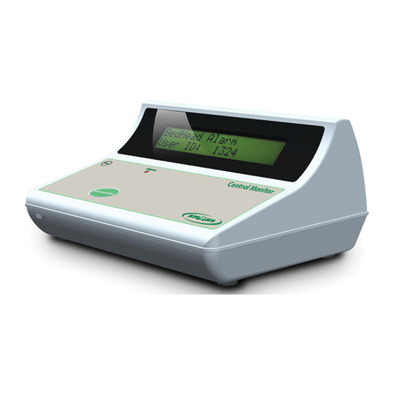
- Page 18 LCD Display: “BedHead Alarm” “User ID: 103” Bed pad “103” = patient has left pad at room 11 bed 3. (or bed 103) LCD Display: “BedPad Alarm” “User ID: 103” Sensor “103” = patient has stepped on loor mat or broken beam sensor. LCD Display: “Sensor Alarm”...
- Page 19 This is for information only to show a restless patient and is not an alert. The display will remain showing this information until another alert or reset button is pressed. Fault detect examples (TL-2015R2 OORC switch “on”) Example a bed transmitter unit is not being received (for example battery needs changing): Fault Bedhead 0203 - bed transmitter fault at “203”...
-
Page 20: List Of Compatible And Associated Equipment
If not, check the AC power (display is on or power LED on for door monitor) 2) Test unit by initiating an alert (press alert button etc) If alarm accepted at TL-2015R2, clear the fault and see if it reappears in 24 hrs. It may be that this unit is just on the edge of its range and the receivers or transponders need adjusting.
Need help?
Do you have a question about the TL-2015R2 and is the answer not in the manual?
Questions and answers