Table of Contents
Advertisement
Advertisement
Table of Contents

Related Manuals for DANA Spicer Torque-Hub C017A1


Summary of Contents for DANA Spicer Torque-Hub C017A1
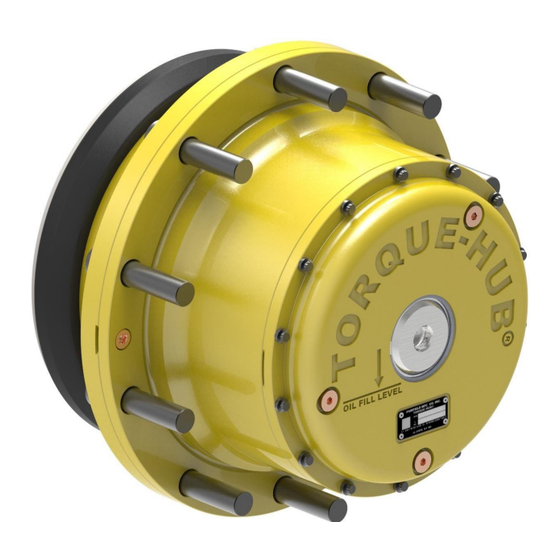
- Page 1 ® Torque-Hub Planetary Final Drive C017A1 Service Manual Rev. 6/6/16...
- Page 2 Fairfield Manufacturing Co. Inc., Lafayette, IN, is now a part of Dana Incorporated While every precaution has been taken in the preparation of this document, Fairfield Manufacturing Co. Inc. assumes no liability with respect to the use of the documentation described herein, or for any act or omission ®...
-
Page 3: Table Of Contents
Planetary Final Drive Service Manual Table of Contents Introduction..............................4 Park Brake Test ............................5 Service Brake Test ............................6 Roll and Leak Test ............................7 Tightening and Torquing Bolts ........................9 Lubrication Information ..........................10 Park Brake Disassembly ..........................12 Main Disassembly ............................ -
Page 4: Introduction
Introduction This manual is a step-by-step guide to the disassembly and assembly ® of the specific Torque-Hub family of units shown on the cover. It is designed for the customer or mechanic who is repairing this particular ® Torque-Hub model. Users of this manual should note that each part mentioned is followed by an identification number enclosed in parentheses. -
Page 5: Park Brake Test
Park Brake Test The Park Brake Test 1) Install Roll and Leak Test fixture into coupling and onto spindle. Install an SAE J1926-1 #6 (9/16-18) O-ring fitting into the “Park” port on the spindle. 2) Apply 25 in-lbs. torque to the input while slowly increasing the pressure to the “Park”... -
Page 6: Service Brake Test
Service Brake Test The Service Brake Test 1) Install Roll and Leak Test fixture into coupling and onto spindle. Install an SAE J1926-1 #6 (9/16-18) O-ring fitting into the “Park” and “Service” ports on the spindle. Release the Park brake by applying 1500 psi to this port. -
Page 7: Roll And Leak Test
Roll and Leak Test ® Torque-Hub units should always be roll and leak tested before disassembly (if possible) and after assembly to make sure the unit’s gears, bearings, and seals are working properly. The following information briefly outlines what to look for when performing these tests. - Page 8 The Leak Test The purpose of a leak test is to make sure the unit is airtight. To perform a leak test use the leak test fixture from the table below. If the tool is not available, the gearbox must be sealed to perform the test. This can be accomplished by replacing one of the oil plugs in the cover with an air chuck.
-
Page 9: Tightening And Torquing Bolts
Tightening and Torquing Bolts If an air impact wrench is used to tighten bolts, extreme care should be taken to ensure the bolts are not tightened beyond their specified torque. The following steps describe how to tighten and torque bolts or socket head cap screws in a bolt circle. -
Page 10: Lubrication Information
Lubrication Information ® General Properties The lubricant used in most Torque-Hub drives should be petroleum based gear fluid containing anti-oxidation, anti-foaming and extreme pressure additives. The lubricant should have a minimum viscosity index of 95 cst and maintain a minimum viscosity of 40 cst under normal operating conditions. - Page 11 DISASSEMBLY...
-
Page 12: Park Brake Disassembly
Park Brake Disassembly Place the gearbox flange up on the bench. Install M6-1.0x20 Bolts (17M) thru the Pressure Plate (17L) into the Piston (17A). Tighten the bolts evenly to compress the Brake Springs (17D). Carefully remove the Retaining Ring (17K). Remove the Piston (17A), this may be done by applying low air pressure to the “PARK”... -
Page 13: Main Disassembly
Main Disassembly Remove Oil Plugs (6H) and drain the oil. Notice the condition of the oil and the volume. Remove the Bolts (15) from the housing. 3) Remove the Sun Gear (6). 4) Remove the Input Carrier Sub-Assembly. 5) Remove the Sun Gear (10H). Continued on Next Page... - Page 14 6) Remove Socket Head Bolts (8) and (9). There are two different lengths. 7) Remove the Bearing Carrier (1M) with the Bearing Cone (1C). 8) Remove the Shims (13) from the Spindle (1A). Note: the shims can be very sharp. 9) Remove the Socket Head Screws (8).
- Page 15 12) Thread Socket-Head Bolt (9) partially into the threaded hole of the Planet Shaft (1N), pull the Planet Shaft (1N) from the Spindle/Carrier while holding onto the Planet Gear. 13) Rotate the housing so that the studs straddle the planet gear. Lift the Planet Gear (1H) from the carrier window.
-
Page 16: Service Brake Disassembly
Service Brake Disassembly 18) Using a pick remove the Rotors (19C 19N) and Stators (19D). CAUTION: Safety glasses must be worn during this next step. 19) Remove the Retaining Ring (19E). There is spring pressure against the retaining ring. 20) Remove the Spacer (19G) and the Wave Spring (19F). Continued on Next Page... - Page 17 21) Remove housing (1G) from Spindle (1A). The Bearing Cup (1C), Seal Boot (1Z), Seal (1B), Piston (19B) will also come off with the Housing (1G). Seal Ring (19A) may also come off with the housing. 22) Remove the Seal Boot (1Z) from the Housing (1G) if the Seal boot (1Z) is to be replaced. 23) Remove the Piston (19B) and Seal Ring (19A) out of the housing.
-
Page 18: Cover Disassembly
Cover Disassembly CAUTION: Safety glasses must be worn during this next step. Remove the Retaining Ring (2B) form the Cover (2). Use a .750 hex driver and remove the Cover Cap (2A). (Threaded) Remove O-ring (2C) from the groove in the Cover Cap (2A). Discard. Remove the O-ring (21) from Cover (2) pilot. -
Page 19: Input Carrier Disassembly
Input Carrier Disassembly Drive the Roll Pin (10E) down into the Planet Shaft (10D). This will allow the Planet Shaft (10D) to be driven from the Carrier (10A). Remove the Planet Gear (10F) with the Needle Rollers (10C) and Thrust Washers (10B). Remove the Thrust Washers (10B) from each end of the Planet Gear (10F). - Page 20 THIS PAGE INTENTIONALLY LEFT BLANK...
- Page 21 ASSEMBLY...
-
Page 22: Input Carrier Subassembly
Input Carrier Subassembly Use grease to install the Needle Rollers (10C) into the bore of the Planet Gear (10F). The last needle roller may need to be slid in axially. Use grease to fix the thrust Washers (10B) into the counter-bores on each side of the planet gear. Repeat steps 1-2 for the remaining planet gears. -
Page 23: Cover Subassembly
Cover Subassembly Use grease to locate the Thrust washer (2D) onto the hub of the Cover (2). Lightly grease the O-ring (21) and assemble it onto cover pilot diameter. Lightly grease the O-ring (2C) and assemble it into the groove on the Cover Cap (2A). Thread the cover cap into the cover and torque to 200-250 ft-lbs. -
Page 24: Main Assembly
Main Assembly Place the Hub (1G) onto the bench with the scalloped end down. Using tool T226197 Press the Seal (1B) into the counter-bore of the hub until the tool stops on the loose ring of the tool (item # 101). Install the Seal Boot (1Z) onto the Housing (1G) with “LOCTITE H3151”... -
Page 25: Service Brake Subassembly
Service Brake Subassembly Install the Wave Spring (19F) onto the Spindle (1A) and into the Piston (19B). CAUTION: Safety glasses must be worn during this next step. 10) Place the Washer (19G) onto the Wave Spring (19F). Put the Retaining Ring (19E) onto the Spindle (1A) against the Washer (19G). - Page 26 15) Install Thrust Spacer (4) into the counter-bore of the Spindle (1A) 16) Liberally grease the bore of the Planet Gear (1H) and install the Needle Rollers (1R). Install the Spacer (1J) and install the remaining Needle Rollers (1R) to complete two paths of needle rollers. 17) Grease and install Thrust Washer (1K) into both counter-bores of the Planet Gear (1H).
- Page 27 22) Grease and install O-ring (19H) into the groove of the Housing (1G). 23) Lower the Housing (19L) onto the Housing (1G). Note: The Ring Gear (19L) will need to be rotated to line up the scallops in the brake flange with the Planet Gears 24) The scallops in the Housing (19L) must be aligned with the planet gears for proper assembly and aligned with the studs and threaded holes in Housing (19L).
- Page 28 26) Install the Shims (13) onto the spindle. NOTE: the shims are sharp. 27) Install the Bearing Carrier (1M) with the Bearing Cone (1C). 28) Insure that the holes in the Spindle (1A) and the threads on the Bolts (8) and (9) are clean and dry. 29) Install the Bolts (8) and (9) (two different lengths) with LOCTITE 263 into the appropriate holes and torque to 69 - 79 ft-lbs.
- Page 29 30) Install Sun Gear (10H) into mesh with planet gears. 31) Install the Input Carrier Sub-Assembly onto the Sun Gear (10H). 32) Install the Sun Gear (6) into the output sun gear and in mesh with the input planet gears. Continued on Next Page...
- Page 30 33) Install the Cover (2) into the Hub (19L). There is no timing requirement. 34) Install Bolts (15) with Loctite 243 and torque to 23-27 ft-lbs. 35) Install the Oil Plugs (6H) and torque to 33-36 ft-lbs. This concludes the Main Assembly.
-
Page 31: Park Brake Subassembly
Park Brake Subassembly Place the gearbox on bench, Spindle (1A) flange up. Place the Input Coupling (11), with retaining rings (20B) and (20C) into the brake cavity in the spindle resting on the Washer (4). Grease and install Quad-Ring (17J) into the small groove in the spindle bore. Grease and install Quad-Ring (17G) into the large groove in the spindle bore. -
Page 32: Assembly Drawing
Assembly Drawing... -
Page 33: Parts List
Parts List Item Qty. Description SPINDLE/CARRIER SEAL BEARING HOUSING PLANET GEAR THRUST SPACER THRUST WASHER BEARING CARRIER PLANET SHAFT NEEDLE BEARING SEAL BOOT COVER COVER CAP RETAINING RING O-RING THRUST WASHER THRUST SPACER RING GEAR SUN GEAR O-RING PLUG RING GEAR SOCKET HEAD CAP SCREW SOCKET HEAD CAP SCREW CARRIER... -
Page 34: Service Kits
PRESURE PLATE BOLT SEALING RING PISTON ROTOR STATOR RETAINING RING WAVE SPRING THRUST WASHER O-RING QUAD RING QUAD RING HOUSING ROTOR RETAINING RING RETAINING RING O-RING STUD O-RING PLUG Service Kits SERVICE BRAKE SEAL KIT AM9024144B PARK BRAKE SEAL KIT AM9024146B PARK BRAKE SPRING KIT AM9024146C... -
Page 35: Assembly Tools
Assembly Tools T226197 (SEAL PRESSING TOOL) - Page 36 T226232 (PISTON & SEAL RING TOOL)
- Page 37 226229 (RETAINING RING PRESSING TOOL)
- Page 38 226235 (SERVICE BRAKE TEST TOOL)
- Page 39 221667 (CARRIER CRADLE TOOL)
- Page 40 226231-1 (ROLLCHECK AND LEAK TEST TOOL)
- Page 41 226231-2 (ROLLCHECK AND LEAK TEST TOOL)
- Page 42 226231-3 (ROLLCHECK AND LEAK TEST TOOL)
-
Page 43: Contact Information
For more information, contact Fairfield today. Mailing Address Dana Incorporated Off-Highway Drive and Motion Technologies 2400 Sagamore Parkway South / P.O. Box 7940 Lafayette, IN 47903 USA... - Page 44 Dana Incorporated Off-Highway Drive and Motion Technologies 2400 Sagamore Parkway South / P.O. Box 7940 Lafayette, IN 47903 USA 765-772-4000 www.grazianofairfield.com...
Need help?
Do you have a question about the Spicer Torque-Hub C017A1 and is the answer not in the manual?
Questions and answers