Table of Contents
Advertisement
Quick Links
Advertisement
Table of Contents

Related Manuals for DANA Spicer Torque-Hub S350 Series


Summary of Contents for DANA Spicer Torque-Hub S350 Series
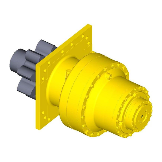
- Page 1 ® Torque-Hub Planetary Final Drive S350 Series Service Manual Rev 04/11/13...
- Page 2 Fairfield Manufacturing Co. Inc., Lafayette, IN, is now a part of Dana Incorporated While every precaution has been taken in the preparation of this document, Fairfield Manufacturing Co. Inc. assumes no liability with respect to the use of the documentation described herein, or for any act or omission of Fairfield Manufacturing ®...
-
Page 3: Table Of Contents
Planetary Final Drive Service Manual Content Introduction Roll and Leak Test Tightening and Torquing Bolts Lubrication Information Disassembly Instructions Main Disassembly Cover Disassembly Output Carrier Disassembly Stage Intermediate Carrier Disassembly Stage Intermediate Carrier Disassembly Input Carrier Disassembly Output Pinion Disassembly Assembly Instructions Cover Subassembly Output Carrier Subassembly... -
Page 4: Introduction
Planetary Final Drive Service Manual Introduction This manual is a step-by-step guide to the disassembly and ® assembly of the S350 series Torque-Hub units. It is designed for the customer or mechanic who is repairing this particular Torque- ® model. Users of this manual should note that each part mentioned is followed by an identification number enclosed in parentheses. -
Page 5: Roll And Leak Test
Planetary Final Drive Service Manual Roll and Leak Test ® Torque-Hub units should always be roll and leak tested before disassembly (if possible) and after assembly to make sure the unit’s gears, bearings and seals are working properly. The following information briefly outlines what to look for when performing these tests. - Page 6 The Leak Test The purpose of a leak test is to make sure the unit is airtight. To perform a leak test, use the leak test fixture from the table on page 10. If the tool is not available, the gearbox must be sealed to perform the test.
-
Page 7: Tightening And Torquing Bolts
Planetary Final Drive Service Manual Tightening and Torquing Bolts If an air impact wrench is used to tighten bolts, extreme care should be taken to ensure the bolts are not tightened beyond their specified torque. The following steps describe how to tighten and torque bolts or socket head cap screws in a bolt circle. -
Page 8: Lubrication Information
Planetary Final Drive Service Manual Lubrication Information ® General Properties The lubricant used in most Torque-Hub drives should be petroleum-based gear fluid containing anti-oxidation, anti-foaming and extreme pressure additives. The lubricant should have a minimum viscosity index of 95 cst and maintain a minimum viscosity of 40 cst under normal operating conditions. - Page 9 ® Maintenance Oil amounts for each series of Torque-Hub drives are indicated in the appropriate series literature. An initial oil change should be made after the first 50 hours of operation. Subsequent oil changes should be made at 1,000 hour intervals or annually, whichever comes first.
- Page 10 THIS PAGE INTENTIONALLY LEFT BLANK...
- Page 11 DISASSEMBLY...
-
Page 12: Main Disassembly
Planetary Final Drive Service Manual Main Disassembly Perform a roll check and a leak check prior to disassembling the unit. Remove the two O-Ring Pipe Plugs (85) and drain the oil out of the gearbox by slightly tilting the whole Unit. NOTE: Record the condition and volume of the oil. - Page 13 Remove four Socket Head Bolts (12) with Washer (13) in X pattern. Remove sixteen Hex Bolts (11) with Washer (13) in X pattern. Lift the Input Cover (5) off of the Unit. Remove two Thrust Washers (9) from the Cover (5). Remove the O-Ring (8) from the groove of the Ring Gear (18) and discard the O-Ring.
- Page 14 Remove Intermediate Sun Gear (7) out of Intermediate Carrier Subassembly. CAUTION: Safety glasses must be worn during these next step. Remove the Retaining Ring (26) from the external groove of the Sun Gear (7). Lift the Intermediate Carrier Subassembly out of the unit. Remove the Spacer (60) from the Output Sun Gear (23).
- Page 15 Remove the Ring Gear (24) from the Housing (32). Remove O-Ring (79) from the Housing (32) and Discard the O-Ring. Remove five Spacers (1) off of the Housing (32) by removing Screws (51). NOTE: Refer page 23 for disassembly instruction of Output Pinion Subassembly. Turn over the Unit and remove the Output Pinion Subassembly out of the Housing (32) by removing Hexagonal Bolts (48) with Flat Washers (49).
- Page 16 THIS PAGE INTENTIONALLY LEFT BLANK...
-
Page 17: Cover Disassembly
Planetary Final Drive Service Manual Cover Disassembly Remove the O-Ring (36) from groove in the Cover (46) and discard O-Ring. Remove Thrust Washers (31) from the Cover (46). Remove Thrust Bearing (39) from the Cover (46). Remove Thrust Washers (30) from the Cover (46). Remove Thrust Washers (38) from the Cover (46). -
Page 18: Output Carrier Disassembly
Planetary Final Drive Service Manual Output Carrier Disassembly Place Output Carrier Subassembly with internal spline side down. Remove Adapter (17D) from the Carrier (17A) by removing twelve Bolts (17E) from the Carrier (17A). Drive the Planet Shaft (17K) out of the Carrier (17A) planet shaft bore.(with punch through small hole at spline end of Carrier (17A).) Slide Planet gear subassembly out of the Carrier (17A) window. -
Page 19: St Stage Intermediate Carrier Disassembly
Planetary Final Drive Service Manual Stage Intermediate Carrier Disassembly Unbend the tang of Lock-Tanged Washer (2I) from the Bearing Nut (2H) and remove the Bearing Nut (2H) from the Planet Shaft (2K). Remove Planet Shaft (2K) from the Carrier (2A). Remove Lock-Tanged Washer (2I) from the Carrier (2A) and discard it. - Page 20 Planetary Final Drive Service Manual Stage Intermediate Carrier Disassembly Remove the three Retainer Plates (27) from the groove of the Carrier (4A) by removing Socket Head Cap Screws (28) from the Internal Coupling (1H). Remove the Internal Coupling (1H) from the Carrier (4A). Remove the Thrust Spacer (1L) from the Internal Coupling (1H).
- Page 21 CAUTION: Safety glasses must be worn during these next steps. Remove Retaining Ring (4E) from internal groove of the Planet Gear (4B). Repeat the steps 4 through 13 for the remaining two Planet Gears (4B). This concludes the 2nd Stage Intermediate Carrier Disassembly.
-
Page 22: Input Carrier Disassembly
Planetary Final Drive Service Manual Input Carrier Disassembly Unbend the tang of Lock-Tanged Washer (3H) from the Bearing Nut (3G) and remove the Bearing Nut (3G) from the Planet Shaft (3E). Remove Planet Shaft (3E) from the Carrier (3A) Remove Lock-Tanged Washer (3H) from the Planet Shaft (3E) and discard it. Remove Lock Pin (3D) from slot of Carrier (3A). -
Page 23: Output Pinion Disassembly
Planetary Final Drive Service Manual Output Pinion Disassembly Remove the fourteen Hex Bolts (47) from Retainer Plate (40) through Spacer (41). Remove the Retainer Plate (40) from the Pinion. Remove the Spacer (41) from the Pinion. Use Bearing Puller and pull Bearing Carrier (33) with Bearing (56) and Seal (54) off the splined end of Pinion Remove Bolts (48) and Washers (49) from Bearing Carrier (33) and lift off Seal Carrier (34). - Page 24 ASSEMBLY...
-
Page 25: Cover Subassembly
Planetary Final Drive Service Manual Cover Subassembly Place Cover (46) with bore side up on the table. Grease and install Thrust Washer (38) onto the Cover (46).The grease should hold the washer in place for assembly. Grease and install Thrust Washer (30) onto the Cover (46) on top of Thrust Washer (38). Grease and install Bearing (39) on top of Thrust Washer (30). -
Page 26: Output Carrier Subassembly
Planetary Final Drive Service Manual Output Carrier Subassembly Place Output Carrier (17A) with internal spline side down. Grease and install O-Ring (17H) into the o-ring groove of Thrust Plate (17G). Install Thrust Plate (17G) into the bore of the Carrier (17A) with O-Ring side down. Align bolt holes in Thrust Plate (17G) with bolt holes in Carrier (17A). - Page 27 Roll all the Planet Gears (17B) to insure they roll freely. Install Adapter (17D) with flange side down onto the Carrier (17A). Apply Loctite-243 and install Hex Bolts (17E) into Carrier (17A) through Adapter (17D).Torque bolts to 80ft-lbs This concludes the Output Carrier Subassembly.
-
Page 28: St Stage Intermediate Carrier Subassembly
Planetary Final Drive Service Manual Stage Intermediate Carrier Subassembly Place Carrier (2A) onto press table. CAUTION: Safety glasses must be worn during these next steps. Place Planet Gear (2B) with part number up onto press table. Install Internal Retaining Ring (2G) into the groove of Planet Gear (2B). - Page 29 Slide Planet Gear (2B) assembly into planet window of Carrier (2A) with Retaining Ring (2G) towards internal spline. Align planet shaft bore in Planet Gear (2B) with Thrust Washer (2F) bore and Carrier (2A) planet shaft bore Inspect the Planet Shaft (2K) for nicks and burs. Insure that the planet shaft hole and Planet Shaft (2K) are free from debris, burrs, sharp corners.
- Page 30 Planetary Final Drive Service Manual Stage Intermediate Carrier Subassembly Place Carrier (4A) onto press table. CAUTION: Safety glasses must be worn during these next steps. Place Planet Gear (4B) with part number up onto press table. Install Internal Retaining Ring (4E) into the groove of Planet Gear (4B).
- Page 31 Slide Planet Gear (4B) assembly into planet window of Carrier (2A) with Retaining Ring (4E) towards internal spline. Align planet shaft bore in Planet Gear (4B) with Thrust Washer (4G) bore and Carrier (4A) planet shaft bore Inspect the Planet Shaft (4K) for nicks and burs. Insure that the planet shaft hole and Planet Shaft (2K) are free from debris, burrs, sharp corners.
-
Page 32: Input Carrier Subassembly
Planetary Final Drive Service Manual Input Carrier Subassembly Place Carrier (3A) onto press table. CAUTION: Safety glasses must be worn during these next steps. NOTE: Bearing (3C) is a matched set and must stay as a set. Place Planet Gear (3F) with part number up onto press table. Install Internal Retaining Ring (3C) into the groove of Planet Gear (3F). - Page 33 Align planet shaft bore in Planet Gear (3F) with Thrust Washer (3B) bore and Carrier (3A) planet shaft bore Inspect the Planet Shaft (3E) for nicks and burs. Insure that the planet shaft hole and Planet Shaft (3E) are free from debris, burrs, sharp corners. Start the Planet Shaft (3E) on the wide side of the Carrier (3A).
-
Page 34: Output Pinion Subassembly
Planetary Final Drive Service Manual Output Pinion Subassembly Place Seal Carrier (19) with larger bore side up onto the press table. Spray the Seal Carrier (19) seal bore with alcohol, then wipe with a clean rag. Insure there is no debris left in the bore. Spray the O.D. - Page 35 Apply Loctite-243 and install Socket Head Bolts (59) onto the Housing (1G) through the Seal Carrier (19). Torque bolts (59) to 80-90 ft-lbs. Place Bearing (56) and Bearing Carrier (33) into oven at 200° F for 3 hours. Place Pinion with splines up. Spray the Seal Carrier (34) seal bore with alcohol, then wipe with a clean rag.
- Page 36 Insure the Bearing Carrier (33) in Pinion assembly has fully seated onto Housing (32). Apply Loctite-243 and install Hex Bolts (48) through Washer (49) into Housing (32) through the Bearing Carrier (33). Torque Bolts to 78-92 ft-lbs. This concludes the Output Pinion Subassembly.
-
Page 37: Main Assembly
Planetary Final Drive Service Manual Main Assembly Place Housing (32) flange side down onto assembly fixture. Install bolts into fixture through Housing (32) flange. Spray the Housing (32) bushing bore with alcohol, then wipe with a clean rag. Insure there is no debris left in the bore. - Page 38 NOTE: Insure not to Grease O-Ring (79) in step below. Install O-Ring (79) onto the Housing (32) o-ring groove. Lower Ring Gear (24) onto the Housing (32) by aligning the Ring Gear (24) teeth with the planet gear teeth of the Output Carrier Subassembly. Insure that the Ring Gear (24) dowelpin holes are aligned with the dowel pins in housing.
- Page 39 Lower Spacer Housing (29) onto Ring Gear (24) with flange side down. Align bolts holes in Spacer Housing (29) with Ring Gear(24) bolt holes. Insure the Spacer Housing (29) has seated against Ring Gear (24). Install four Hex Bolts (52) through Washer (53) into the Spacer Housing (29). Torque Bolts (52) to 680 ft-lbs.
- Page 40 Lower Sun Gear (23) with spline side up into the output planet gear mesh. Insure Sun Gear (23) is engaged with planet gears of Output Carrier Subassembly.. Install Spacer (60) onto the Sun gear (23). Lower Intermediate Carrier Subassembly with internal coupling side down onto sun gear (23).
- Page 41 Lower Intermediate Carrier subassembly (2) into the Ring Gear (18). Rotate the planet gears slowly until the planet gear drops into engagement with Ring Gear (18) teeth and Carrier splines with Sun Gear (7) splines. Install Sun Gear (6) into the planet gear mesh. Spray the internal components with RP oil.
- Page 42 Grease and install Thrust Washer (43) onto the Intermediate Sun Gear (6). The grease should hold the Washer (43) in place for assembly. Grease and install O-Ring (36) onto the Cover (5). Insure that the O-Ring (26) is fully seated. Install Input Carrier Subassembly (3).
-
Page 43: Assembly Drawing
Planetary Final Drive Service Manual Assembly Drawing... -
Page 44: Parts List
Planetary Final Drive Repair Instructions Parts List Number Description FLT HD HEX BOLT WASHER THRUST PLUG PLANET SHAFT SPACER(SPECIAL) BEARING CARRIER SEAL CARRIER SUN GEAR PLANET GEAR RING GEAR RETAINER PLATE SPACER THRUST HUB SPACER HOUSING MAIN HOUSING CARRIER CARRIER CARRIER CARRIER PLANET GEAR... - Page 45 Number Description BEARING CONE THRUST WASHER PLANET SHAFT BEARING CUP BEARING CONE THRUST WASHER 2F4G THRUST WASHER RETAINER PLATE THRUST SPACER THRUST BEARING THRUST WASHER INPUT COVER O-RING ROLLER BEARING STEEL BUSHING ROLLER BEARING STEEL BUSHING SPACER ID PLATE LIP SEAL LIP SEAL RETAINIGN RING RETAINIGN RING...
- Page 46 PIPE PLUG PLANET GEAR COUPLING LOCK WASHER TANGED LOCK WASHER 2I4I TANGED LOCK WASHER FLAT WASHER THRUST WASHER BEARING NUT 2H4H BEARING NUT GREASE FITTING...
-
Page 47: Assembly Tools
Planetary Final Drive Repair Instructions Assembly Tools T149933 – LOCKNUT WRENCH... - Page 48 T158149 – BEARING CUP PRESS TOOL...
- Page 49 T170237 – LEAK TEST ADAPTOR...
- Page 50 T214147 – ASSEMBLY PRESSING TOOL...
- Page 51 T216332 – ASSEMBLY PRESSING TOOL...
- Page 52 T222390 – LEAK TEST ADAPTER PLATE...
- Page 53 T223131 – LOCKNUT WRENCH...
- Page 54 T223989 – ROLL CHECKING TOOL...
-
Page 55: Contact Information
For more information, contact Fairfield Manufacturing Co Inc. today. Mailing Address Dana Incorporated Off-Highway Drive and Motion Technologies 2400 Sagamore Parkway South / P.O. Box 7940 Lafayette, IN 47903 USA... - Page 56 Dana Incorporated Off-Highway Drive and Motion Technologies 2400 Sagamore Parkway South / P.O. Box 7940 Lafayette, IN 47903 USA 765-772-4000 www.grazianofairfield.com...
Need help?
Do you have a question about the Spicer Torque-Hub S350 Series and is the answer not in the manual?
Questions and answers