Table of Contents
Advertisement
Advertisement
Table of Contents

Related Manuals for LG CE-21F66X


Summary of Contents for LG CE-21F66X
- Page 2 website:http://biz.LGservice.com e-mail:http://www.LGEservice.com/techsup.html COLOR TV SERVICE MANUAL CHASSIS : MC-00AA MODEL : CE-20/21F66/66X MODEL : CE-20/21F86X CAUTION BEFORE SERVICING THE CHASSIS, READ THE SAFETY PRECAUTIONS IN THIS MANUAL. Dec.,2000 P/NO : 3828VD0078D Printed in Korea...
-
Page 3: Table Of Contents
CONTENTS Contents ......................... 2 Safety Precautions ....................3 Servicing Precautions ..................4 Specifications ..................... 6 Description of Controls .................. 7 Disassembly Instructions ................10 Adjustment ......................11 Purity & Convergence Adjustment ............14 Exploded View ....................18 Exploded View Parts List ................19 Replacement Parts List ................22 SVC. -
Page 4: Safety Precautions
SAFETY PRECAUTIONS IMPORT ANT SAFETY NOTICE Many electrical and mechanical parts in this chassis have special safety-related characteristics. These parts are identified by the Schematic Diagram and Replacement Parts List. It is essential that these special safety parts should be replaced with the same components as recommended in this manual to prevent X-RADIATION, Shock, Fire, or other Hazards. -
Page 5: Servicing Precautions
SERVICING PRECAUTIONS CAUTION: Before servicing receivers covered by this service transistors and semicounductor "chip" components. The manual and its supplements and addenda, read and follow the following techniques should be used to help reduce the SAFETY PRECAUTIONS on page 3 of this publication. incidence of component damage caused by static by static NOTE: If unforeseen circumstances create conflict between the electricity. - Page 6 c. Qulckly move the soldering iron tip to the junction of the Fuse and Conventional Resistor component lead and the printed circuit foil, and hold it Removal/Replacement there only until the solder flows onto and around both the 1. Clip each fuse or resistor lead at top of the circuit board component lead and the foil.
-
Page 7: Specifications
SPECIFICA TIONS Note : Specification and others are subject to change without notice for improvement. ¡ Video input system: SOUND IF : 33.4MHz (B/G) PAL-B/G, D/K, I/I 32.9MHz (I/I) SECAM-B/G, D/K/L/L’ 32.4MHz (D/K,L) NTSC M 34.4MHz (M) 40.4MHz (L’) ¡ Intermediate Frequency (Unit : MHz) VISION IF : 38.9MHz,33.9MHz(SECAM-L’) COLOR IF : 34.47MHz(4.43) ¡... -
Page 8: Description Of Controls
PLAY These buttons are used for teletext. For further details, see the ‘Teletext’ section. P/STILL STOP 8. VCR BUTTONS (option) control a LG video cassette recorder. 9. MUTE switches the sound on or off. With TELETEXT 10. TV/AV selects TV or AV mode. - Page 9 11. ARC (Aspect Ratio Control) changes the picture format. 12. SURROUND ( ) (option) º selects surround sound. 13. Q. VIEW returns to the previously viewed programme. 14. LIST MUTE POWER displays the programme table. I/II/ 15. SSM/ (Sound Status Memory) (option) recalls your preferred sound setting.
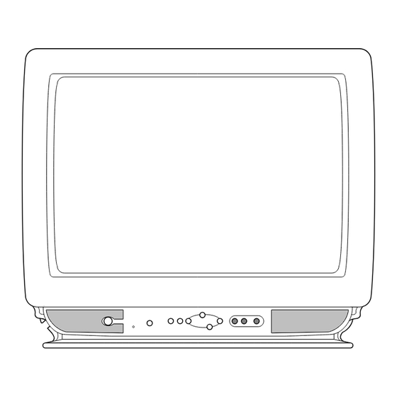
- Page 10 Front panel Shown is a simplified representation of front panel. Here shown may be somewhat different from your set. Mono models POWER OK F F VOL G G E E PR D D § § MENU VIDEO AUDIO POWER MENU OK F F VOL G G E E PR D D §...
-
Page 11: Disassembly Instructions
DISASSEMBLY INSTRUCTIONS Chassis Assy Removal Important note Grasp both side of Frame and pull it backward smoothly. This set is disconnected from the power supply through the converter transformer. An isolating transformer is necessary for service operations on the primary side of the converter transformer. -
Page 12: Adjustment
6700VPF005D Tuner P/N 2. Never disconnect leads while the TV receiver is on. 3. Don't short any portion of circuits while power is on. LG Innotek LG Innotek Marker 4. The adjustment must be done by the correct appliances. But this is changeable in view of productivity. - Page 13 located within the effective screen of the CPT. SC (Vertical “S” Correction) Adjust so that all distance between each horizontal lines are to be the same. VS (Vertical Shift) Adjust so that the horizontal center line of a digital circle pattern is in accord with geometric horizontal center of the CPT.
- Page 14 ¡ OPTION Adjustment (SVC MODE:OPTION-1, OPTION-2) Option Code Function Remark EUROPE STANDARD VOL CURVE NOTE: When the EEPROM has been replaced, the Option data should be restored as the function of individual system and specification. TURBO P/S OFF T P/S TURBO P/S ON 1) Press OK buttons on both TV set and Remote Controller at the same time to get into SVC mode.
-
Page 15: Purity & Convergence Adjustment
PURITY & CONVERGENCE ADJUSTMENT Caution: 5. Reconnect the internal degaussing coil. Convergence and Purity have been factory aligned. Do not attempt to tamper with these alignments. 6. Position the beam bender locking rings at the 9 o'clock However, the effects of adjacent receiver components, or position and the other three pairs of tabs (2,4 and 6 pole replacement of picture tube or deflection yoke may require the magnets) at the 12 o'clock position. - Page 16 1.ADJUST YOKE Z-AXIS FIRST 2 .ADJUST BEAM BENDER 2 POLE TO GET EQUAL BLUE MAGNET TO GET FOUR EQUAL COLOR CIRCLES COLOR CIRCLES MAGNETS 8. Referring to above, perform the following two steps: 6. Reconnect the internal degaussing coil and apply AC power. a.
- Page 17 ROTATION DIRECTION RING MOVEMENT OF RED OF BOTH TABS PAIRS AND BLUE BEAMS OPPOSITE POLE SAME OPPOSITE POLE SAME UP/DOWN ROCKING OF THE YOKE LEFT/RIGHT ROCKING OF THE YOKE UP/DOWN ROCKING OF THE YOKE LEET/RIGHT ROCKING OF THE YOKE CAUSES OPPOSITE ROTATION OF RED CAUSES OPPOSITE SIZE CHANGE OF THE CAUSES OPPOSITE ROTATION OF RED CAUSES OPPOSITE SIZE CHANGE OF...
- Page 18 MEMO - 17 -...
-
Page 19: Exploded View
EXPLODED VIEW:20/21F66X P801 OPTION - 18 -... -
Page 20: Exploded View Parts List
The components identified by mark critical for safety. EXPLODED VIEW PARTS LIST Replace only with part number specified. PART NO LOCA. NO DESCRIPTIONS 20" 21" 343-B52A 343-B52A SUPPORTER,PCB 2055-V1221B 6341V21006B 6400VA0019A 6400VA0019A SPEAKER,GENERAL G9050401 8 OHM 5/ 150-D02Y 150-D02X COIL,DEGAUSSING 153-276A 6150Z-1023A 170-A01D... - Page 21 EXPLODED VIEW:20F86X P801 OPTION - 20 -...
- Page 22 The components identified by mark critical for safety. EXPLODED VIEW PARTS LIST Replace only with part number specified. LOCA. NO PART NO DESCRIPTIONS 343-B52A SUPPORTER,PCB 2055-V1221B CPT,A48QAD220X 03N7ND(+0.4) 6400VA0019A SPEAKER,GENERAL G9050401(C93G) 8 OHM 150-D02Y COIL,DEGAUSSING CU 20” 60T 15 OHM 153-276A DY,DCAM1-20PLAA 170-A01D...
-
Page 23: Replacement Parts List
The components identified by mark critical for safety. REPLACEMENT PARTS LIST Replace only with part number specified. LOCA. NO PART NO DESCRIPTION LOCA. NO PART NO DESCRIPTION D807 0DD300009AC DIODE,RECTIFIER RU3AMV(1) D808 0DD200009AF DIODE,RECTIFIER RU2M V(1) IC01 0ISM555000B IC,SDA555XFL 52DIP ST FLASH MEMOR D813 0DD414809ED DIODE,1N4148 TA... - Page 24 The components identified by mark For Capacitor & Resistors, CC, CX, CK, CN : Ceramic RD : Carbon Film the charactors at 2nd and 3rd CQ : Polyestor RS : Metal Oxide Film critical for safety. digit in the P/No. means as CE : Electrolytic RN : Metal Film Replace only with part number specified.
- Page 25 The components identified by mark For Capacitor & Resistors, CC, CX, CK, CN : Ceramic RD : Carbon Film critical for safety. the charactors at 2nd and 3rd CQ : Polyestor RS : Metal Oxide Film digit in the P/No. means as CE : Electrolytic RN : Metal Film Replace only with part number specified.
- Page 26 The components identified by mark For Capacitor & Resistors, CC, CX, CK, CN : Ceramic RD : Carbon Film the charactors at 2nd and 3rd CQ : Polyestor RS : Metal Oxide Film critical for safety. digit in the P/No. means as CE : Electrolytic RN : Metal Film Replace only with part number specified.
- Page 27 The components identified by mark For Capacitor & Resistors, CC, CX, CK, CN : Ceramic RD : Carbon Film critical for safety. the charactors at 2nd and 3rd CQ : Polyestor RS : Metal Oxide Film digit in the P/No. means as CE : Electrolytic RN : Metal Film Replace only with part number specified.
- Page 28 2.4K 1/6W 5 TA52 ACCESSORIES R808 0RD4701F609 4.70K 1/6W 5% TA52 R809 0RS4702K607 47K 2W 5% TA62 3828VA0221L MANUAL,OWNERS MK/REG LG HU/EN 028R/05 R811 0RS0391K607 3.90 2W 5% TA62 6710V00056B REMOTE CONTROLLER TXT&W/O TURBO R812 0RKZVTA001C 8.2M OHM 1/2 W 5% TA52...
- Page 29 Service Sheet Of MC-00AA P/No : 3854VA0076A-S1 2000.09.09...
- Page 30 PRINTED CIRCUIT BOARD WIRING DIAGRAM COMPONENT LOCATION GUIDE MAIN & CPT C708..E5 F801A ..G2 P207 ..B3 R07 ..C2 R212 ..D4 R609..A2 Z103 ..C5 C02 ..C1 C301..E4 C302..E4 C709 ..G4 F801B ..G1 P208 ..B3 R08 ..C1 R213 ..D4 R610..B2 Z104 ..B4 C03 ..C2 C303..E4 C710 ..G5...
-
Page 31: Svc. Sheet
SVC. SHEET : 3854V A0076A-S...
Need help?
Do you have a question about the CE-21F66X and is the answer not in the manual?
Questions and answers