Table of Contents
Advertisement
Quick Links
Advertisement
Table of Contents

Summary of Contents for ROPA Tiger 6
- Page 1 Translation of the Translation of the Original Operating Manual Original Operating Manual Tiger 6 with RR lifting unit Tiger 6 with RR lifting unit Edition 3 Edition 3 Software version: 19T0017 Software version: 19T0017 Printed in Germany: 07/2019 Printed in Germany: 07/2019...
- Page 2 – with the express approval of ROPA GmbH. Any type of reproduction, distri- bution or storage on data medium in any form and of any type not authorised by ROPA GmbH forms a violation of current domestic and international copyright law and will be judicially prosecuted.
- Page 3 Contents Contents 3 / 564...
- Page 4 Contents 4 / 564...
-
Page 5: Table Of Contents
Contents Preface................. 13 Name plate and important data...............17 Type overview..................18 Serial numbers and name plates............19 Declaration of Conformity................ 21 Safety................23 General....................25 Obligations of the entrepreneur...............25 General symbols and instructions............25 2.3.1 Safety signs..................... 26 Proper use....................27 2.4.1 Foreseeable misuse................ - Page 6 Contents 5.1.2 Ladder bunker..................61 Driver's cabin overview................62 Steering column..................64 5.3.1 Steering column switch................65 Driver’s seat.....................66 Operating components on the floor of the driver‘s cabin......72 Operating console R-Concept..............73 5.6.1 Colour terminal R-Touch................74 5.6.1.1 Positioning R-Touch.................75 5.6.2 R-Select....................76 5.6.3 R-Direct....................
- Page 7 Contents 6.3.4 Light control................... 145 6.3.4.1 Configure light programs............... 146 6.3.4.2 Ladder light.................... 146 Joystick....................147 Diesel engine..................154 6.5.1 Start/shut down diesel engine............... 157 6.5.2 Engine speed adjustment..............159 6.5.3 Power reduction SCR system (only at RT6c)........161 6.5.3.1 Power reduction AdBlue filling level............162 6.5.3.2 Power reduction AdBlue quality and system error........
- Page 8 Contents 6.10.2.10 Quick description: steering modes in operating mode "Field"....209 6.10.3 Automatic steering (Autopilot)............... 210 6.10.3.1 Activating autopilot front axle steering..........210 6.10.3.2 Quick description: activating only front axle autopilot......211 6.10.3.3 Activating rear wheels autopilot............212 6.10.3.4 Quick description: manual activation of rear wheels autopilot....214 6.10.3.5 Quick description: automatic activation of rear wheels autopilot...
- Page 9 Operating panel bunker emptying............326 6.19.2 Adjustment of unloading stage 2 cross conveyor speed....... 333 6.19.3 Setting the unload rotating speed............334 6.19.4 Instruction on piles creation (with the ROPA loader)......335 6.20 Pump distributor gears................336 6.21 Hydraulic system................... 337 6.22 Compressed air system.................341...
- Page 10 Cooling system diesel engine............... 379 7.1.4.1 Cleaning of the cooling system............. 380 7.1.4.2 Checking coolant................... 383 7.1.4.3 Replacing coolant.................. 384 7.1.4.4 Remarks of ROPA on the coolant (general information)....... 385 7.1.5 Valve clearance adjustment..............385 7.1.6 SCR exhaust after-treatment with AdBlue ........... 386 ® 7.1.6.1 Exchanging the AdBlue filter insert............386...
- Page 11 Contents 7.8.5 Scalper....................427 Lifter....................... 429 7.9.1 Lifting shares..................429 7.9.2 Lifter gears for lifting rollers..............432 7.9.3 Paddle gears..................434 7.9.4 RR 6-row depth-control roller drive............435 7.9.5 Shaking share gears................436 7.9.6 Shaking share drive only with the "variable row distance" option..437 7.9.7 Eccentric shaft bearing................438 7.9.8...
- Page 12 AdBlue® information sheet..............547 Maintenance verification................ 550 9.9.1 Maintenance verification oil change + filter exchange......550 9.9.2 Maintenance confirmation..............552 9.9.3 Software updates...................552 9.10 Confirmation about instructions given to the driver....... 553 9.11 Safety instructions................. 554 9.12 ROPA Handover confirmation............... 556 Index................559 12 / 564...
-
Page 13: Preface
Preface Preface 13 / 564... - Page 14 Preface 14 / 564...
- Page 15 They conform to the high ROPA standards for safety and reliability. We would like to point out that parts and accessories not approved by ROPA may not be used on ROPA machines, otherwise the safety and operability of the machine may be impaired.
- Page 16 We expressly point out that any damage caused by the fact that this operating man- ual is not or not completely followed is not covered by the statutory warranty of ROPA. Even though this operating manual is comprehensive, in your own interest you should completely and carefully read it and slowly familiarize yourself with the machine using this operating manual.
-
Page 17: Name Plate And Important Data
Please enter the data of your machine in the following image of the name plate. You will need this data for ordering spare parts. If you have not yet exchanged the defo- liator unit and/or lifting unit, these may also be identified by ROPA using the chassis number. -
Page 18: Type Overview
Preface Type overview Type overview Classification of the defoliator identification by example of ROPA "RBSO-45": → R ROPA version → B Leaf-spreader defoliator including leaf auger Integrated defoliator All-round defoliator Rubber defoliator → S Defoliator → O Eastern version (4 depth-control wheels) -
Page 19: Serial Numbers And Name Plates
Preface Serial numbers and name plates Serial numbers and name plates The serial number of the engine (1) is located on the engine block. Viewed from the bunker in the direction of forward movement it can be found on the right on the belt side of engine under the intake manifold. - Page 20 Preface Serial numbers and name plates The serial number (3) of the defoliator is located on the left side or top of the defoliator side wall. RIS defoliator RASW/RASO defoliator RES rubber-defoliator 20 / 564...
-
Page 21: Declaration Of Conformity
The Declaration of Conformity belongs to separately provided documents and is handed over on the delivery of the machine. The CE marking of the machine is a constituent part of the nameplate. ROPA TIGER 6 from 6*1449 from 2015 2016-09-01... - Page 22 Safety 22 / 564...
-
Page 23: Safety
Safety Safety 23 / 564... - Page 24 Safety 24 / 564...
-
Page 25: General
Safety General symbols and instructions General The machine has been manufactured according to the current state of technology and tested for safety. The machine is CE compliant and therefore conforms to the respective European reg- ulations for free movement of goods within the European Union respectively the Euro- pean economic region. -
Page 26: Safety Signs
Safety General symbols and instructions CAUTION This signal word warns you of a possibly dangerous situation which may lead to seri- ous injury or to death and damage to the machine or other serious property dam- age. Non-observance of these instructions may lead to loss of warranty. This hazard may always occur if the operating or working instructions are not or only imprecisely observed. -
Page 27: Proper Use
Safety Proper use Warning against explosion hazard, battery area This warning symbol stands for activities during which the hazards of corrosive liquid and gases exist. Warning against falling hazard This warning symbol stands for activities during which the hazards of falling with possi- ble deadly consequences exist. -
Page 28: Hazard Zone
Safety Hazard zone Hazard zone Hazard zone does not apply to RIS* and RES* Keep clear of the hazard zone during operation of the machine. The operator must immediately shut down the machine in case of any threatening hazard and request the people concerned to leave the hazard zone immediately. - Page 29 The meaning of each individual pictograph is explained below. In addition, a six-fig- ure number is given for each pictograph. This is the ROPA order number. Stating this number, you may reorder the respective pictograph from ROPA. The number stated in brackets is printed on the respective sticker.
-
Page 30: Safety Stickers On The Machine
Safety Safety stickers on the machine Safety stickers on the machine The illustration shows an example of a machine with the RR-45 and RIS-45 harvesting attachment 30 / 564... - Page 31 Safety Safety stickers on the machine 355007000 (34) 355006800 (39) Shut down the engine before per- Hazard due to electrical current! forming maintenance and repair Observe a sufficiently safe distance work and pull out the ignition key. to high-voltage power lines. Read the operating manual and comply with remarks on safety.
-
Page 32: Safety And Health Protection
Safety Safety and health protection 355007700 (25) Hazard that body parts can be pulled in. Do not reach into the rotating rollers. Do not climb on the rollers. Never step into the loading areas when the drive activated and motor run- ning. -
Page 33: Requirements For Operating And Maintenance Personnel
All maintenance work which is not specifically the responsibility of the operator may only be carried out by instructed or trained maintenance personnel. Some activities may only be performed by people expressly authorised by ROPA for these activities. In case of doubt, ask the manufacturer whether you may perform a specific activity yourself without any hazard. -
Page 34: Residual Risks
Safety Hazards caused by electricity 2.12 Residual risks Residual risks are special hazards involved in the use of the machine which cannot be fully eliminated despite a safety-conscious design. These residual risks are not readily recognizable and may result in injury or damage to health. In the event such unforeseen residual risks become apparent, the machine must be shut down immediately and the responsible supervisor informed accordingly (if applic- able). -
Page 35: Hazards Caused By Process Materials
Safety Hazards caused by noise 2.15 Hazards caused by process materials WARNING Oil, fuel and grease can cause the following damages: poisoning by inhalation of fuel vapours, allergies due to skin contact with fuel, oil or grease, fire and explosion hazard due to smoking or the use of fire or naked flame when handling fuel, oil or grease. -
Page 36: Hazards Caused By The Hydraulic System
Safety Hazards caused by hot substances/surfaces 2.17 Hazards caused by the hydraulic system WARNING Hydraulic fluid may cause irritation of the skin. Leaking hydraulic fluid may damage the environment. High pressure and partially high temperatures exist within hydraulic systems. Hydraulic fluid emitting at high pressure may enter the body through the skin and cause the most severe tissue damage and scalding. -
Page 37: Personal Protective Equipment
Safety Leakage 2.20 Personal protective equipment Wear tight-fitting clothing to prevent accidents. Particularly, do not wear ties, scarves, rings or chains that may be caught by moving machine parts. Wear appropriate head- gear for long hair. Do not carry highly inflammable objects, e.g. matches and lighters in your pockets. All persons staying within the area of effect of the machine are situationally obliged to wear the following protective equipment: Always... -
Page 38: General Notes On Safety When Handling Acid Batteries
Safety Prohibition of unauthorised modifications and alterations 2.22 General notes on safety when handling acid batteries Fire, sparks, smoking and open flames are prohibited. Avoid generation of sparks formed by connecting and disconnecting electrical loads or measuring devices directly to battery terminals. Before connecting and disconnecting batteries, switch off the main battery switch. -
Page 39: Safety And Protective Equipment
Safety Safety and protective equipment 2.24 Safety and protective equipment Perform a documented function test after work on safety equipment. Perform a regular function check of safety equipment, keep maintenance intervals. The safety equipment of the machine consists of: Emergency stop switch in the operating console. Back run warning system. -
Page 40: Emergency Exit
Safety Emergency exit 2.25 Emergency exit Depending on the design, the machine is not equipped with a dedicated emergency exit. If the driver's cabin is deformed by external forces, e.g. during an accident, the driver's cabin can generally be exited via the access doors since these doors are glazed with safety glass. -
Page 41: General View And Specifications
General View and Specifications General View and Specifications 41 / 564... - Page 42 General View and Specifications 42 / 564...
-
Page 43: General View
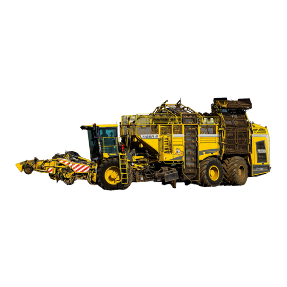
General View and Specifications General view General view This overview is intended to familiarize you with the most important components of your machine. Bunker auger Unload elevator Hydraulic oil tank Engine compartment Climbing ladder bunker Strainer wheel cleaner Climbing ladder driver's cabin Lifting unit Leaf-spreader (not shown here, only with RBS/RAS) (10) - Page 44 General View and Specifications General view Machine ready for driving on roads Shown here including the option additional chassis (See Page 183) 44 / 564...
- Page 45 General View and Specifications General view Shown here without the optional additional chassis. (See Page 183) 45 / 564...
-
Page 46: Technical Data
515 kW / 700 hp Max. torque: 3260 Nm/1250 rpm 3200 Nm/1260 rpm Rated speed (engine manufacturer): 1900 rpm 1800 rpm Rated speed (ROPA): 1600 rpm Maximum speed: 1690 rpm Engine type: Diesel engine 4-stroke, direct fuel injection Displacement: 16 120 cm³... - Page 47 General View and Specifications Technical data Designation: RT6a RT6c 800/70 R38 (184A8) (standard) Tyres front axle: 900/60 R38 (184A8) (optional only with 50 cm or XL) Michelin CEREXBIB 1050/50 R32 (178A8) Michelin MEGA X BIB Tyres 1nd rear axle: Tyres 2nd rear axle: 1000/55 R32 (188A8) Michelin CEREXBIB Tyres additional chassis (optional):...
-
Page 48: Tyre Pressure
General View and Specifications Tyre pressure Tyre pressure min. max. Tyre type min. Recommendation max. (plain+slight slopes) Front axle 800/70 R38 900/60 R38 1st rear axle 1050/50 R32 1000/55 R32 2nd rear axle 1050/50 R32 1000/55 R32 Others min. Recommenda- max. -
Page 49: Transport Draft For Low-Loader Transport Of Machine Without Additional Chassis
General View and Specifications Transport draft for low-loader transport of machine without additional chassis Transport draft for low-loader transport of machine without additional chassis All data in mm. 49 / 564... -
Page 50: Transport Draft For Low-Loader Transport Of Machine With Additional Chassis
General View and Specifications Transport draft for low-loader transport of machine with additional chassis Transport draft for low-loader transport of machine with additional chassis All data in mm. 50 / 564... -
Page 51: Lashing Eyes For Transport By Low-Loader/Ship
General View and Specifications Lashing eyes for transport by low-loader/ship Lashing eyes for transport by low-loader/ship The front axle is equipped with eyes for clamping it down in ground direction. These eyes are located on the right and left next to the mount point for the axle support cylinders. - Page 52 General View and Specifications Lashing eyes for transport by low-loader/ship Lashing eyes on the front axle Lashing eye behind the 2nd axle Lashing eye over the 3rd axle Image shows as an example euro-Tiger (MAN) The machine has no attachment points by which it can be lifted. For hoisting it into a ship for example, special, approved and TÜV-approved lifting devices are necessary.
-
Page 53: General Description
General Description General Description 53 / 564... - Page 54 General Description 54 / 564...
-
Page 55: Function
General Description Function Function The machine is a self-propelled working machine for lifting sugar beets. The lifted beets are collected in the bunker. When the bunker is filled up, the sugar beets may either be deposited in a pile or directly loaded onto an accompanying vehicle using the unloading conveyor. -
Page 56: Scope Of Delivery
General Description Scope of delivery Scope of delivery The scope of delivery of the machine includes a fire extinguisher, a first-aid kit, 4 wheel chocks and a tool set with small parts package. The first-aid kit is located in the driver's cabin, the fire extinguisher on the platform before the driver's cabin door. -
Page 57: Operating Components
Operating Components Operating Components 57 / 564... - Page 58 Operating Components 58 / 564...
-
Page 59: Ladders
Operating Components Ladders Ladders DANGER – Nobody may stay on the platform in front of the driver‘s cabin and bunker door when the machine works. – Ascend ladders and machine only when the machine stands still! Use of ladders See Page 33 5.1.1 Ladder driver's cabin Ladder to driver's cabin in transport respectively working position... - Page 60 Operating Components Ladders ADVICE We recommend to fold up and lock this ladder during lifting! Thus, the forbidden climb- ing on the machine is not possible while driving! 60 / 564...
-
Page 61: Ladder Bunker
Operating Components Ladders 5.1.2 Ladder bunker Rope bunker ladder Bunker ladder unlocking rope Pull the unlocking rope (4) to release the ladder, pull the ladder down at the same time with the pull rope (3). Bunker ladder and platform are ready for ascend Bunker door lock Lower ladder part Fold down the lower half of the ladder (2) until stop. -
Page 62: Driver's Cabin Overview
Operating Components Driver's cabin overview Driver's cabin overview Roof console Roof console storage compartment Roller blind Video monitor Steering column Operating console at driver’s seat Bottle holder Central electrical system cover Rear driver's cabin wall storage compartment (10) Emergency seat (11) Cool box (12) - Page 63 Operating Components Driver's cabin overview (13) First-aid box (14) Blow gun (15) USB interface 63 / 564...
-
Page 64: Steering Column
Operating Components Steering column Steering column DANGER Hazard of deadly injuries if the steering column is moved while driving. In this case, the machine can go out of control and cause the severest damages. – Therefore, NEVER move the steering column while driving! Rotating handle (1) height adjustment Release rotating handle (1) (turn to the left), move the steering column to the desired height, retighten the rotating handle (turn to the right) and block the steering column. -
Page 65: Steering Column Switch
Operating Components Steering column 5.3.1 Steering column switch – Press lever to the right: Turn indicator right (R) – Press lever to the left: Turn indicator left (L) – Lever up/down: driving lights/high beam/headlight flasher (F) – Pressure switch on the end: Horn (H) –... -
Page 66: Driver's Seat
Operating Components Driver’s seat Driver’s seat Safety instructions: To prevent damage to the driver’s back, the seat must be adjusted for the driver’s weight before use and before every change of driver. To prevent injury, no objects should be placed within the moving area of the driver’s seat. - Page 67 Operating Components Driver’s seat Height adjustment The seat height can be set pneumatically and is infinitely adjustable. The seat height can be altered by pulling or pressing the actuator lever (arrow). If the adjustment reaches the top or bottom end stop, the height is adjusted automat- ically in order to guarantee a minimum spring travel.
- Page 68 Operating Components Driver’s seat Headrest The headrest can be individually adjusted for height by pulling it upward over the various increments up the end stop. By pushing forward or backward the angle of the headrest can be adjusted individually. To remove the headrest, pull it over the end stop.
- Page 69 Operating Components Driver’s seat Armrest The armrests can be folded up backward if required. Armrest inclination The inclination of the armrest can be modified by turning the adjustment hand wheel (arrow). 69 / 564...
- Page 70 Operating Components Driver’s seat Backrest adjustment CAUTION Take care with the backrest frame – it may jerk forward and cause injury! – Hold the backrest hand tight before adjusting. The backrest is adjusted using the locking lever (arrow). The locking lever must latch into the desired position.
- Page 71 Operating Components Driver’s seat Cleaning Dirt can impair the function of the seat. Make sure you keep your seat clean. It is not necessary to remove the uphol- stery from the seat frame for cleaning. Avoid soaking the upholstery when clean- ing the upholstered surface.
-
Page 72: Operating Components On The Floor Of The Driver's Cabin
Operating Components Operating components on the floor of the driver‘s cabin Operating components on the floor of the driver‘s cabin Opener for cleaning flap Foot switch autopilot Foot switch driving direction Brake pedal Drive pedal 72 / 564... -
Page 73: Operating Console R-Concept
Foldable armrest with storage compartment Switches on operating console (10) Joystick with multi-functional handle (11) Main steering switch (12) Lever height adjustment operating console ADVICE Use only the USB stick supplied by ROPA or a similar stick formatted in FAT 32. 73 / 564... -
Page 74: Colour Terminal R-Touch
Operating Components Operating console R-Concept Printer and outlets at the front side of the operating console (13) Outlet 24V/8A maximum (14) Outlet 12V/5A maximum (15) Printer (option) 5.6.1 Colour terminal R-Touch With R-Touch (1) different settings can be performed only by touching on the screen. -
Page 75: Positioning R-Touch
Operating Components Operating console R-Concept 5.6.1.1 Positioning R-Touch The R-Touch colour terminal has four different ways to change its position in order to operate it optimally. Adjustment of the operation panel (1): Hereby the whole carrier tube can be rotated forward and backward. Fold the operating console backwards, loosen the knurled screw, swing the holding tube to the desired position and tighten the knurled screw. -
Page 76: R-Select
Operating Components Operating console R-Concept 5.6.2 R-Select The R-Select (2) (BLUE screen and operating panel colour) allows the driver to per- form about 20 different functions without knowing the menu structure. There are no submenus here which require additional knowledge. Generally, there are two possibili- ties to operate the R-Select mode. - Page 77 Operating Components Operating console R-Concept Rpm infeed conveyor R-Select mode (e.g. rpm infeed conveyor is selected) 77 / 564...
- Page 78 Operating Components Operating console R-Concept The following functions are included in R-Select mode: Service position defoliator Fold leaf sensor Elevator rpm Defoliator pressure relief left Defoliator flap up/down (only Defoliator pressure relief right with RAS) Leaf-spreader rpm (not with RIS) Pressure stone protection Rpm defoliator shaft Leaf-spreader fold/unfold (not...
-
Page 79: R-Direct
Operating Components Operating console R-Concept 5.6.3 R-Direct The R-Direct function area (5) (YELLOW screen and operating panel colour) allows the driver to perform different settings, e.g. access to the main menu with submenus. When touching one of the R-Direct selecting field (5) the R-Touch accepts commands as well as when turning or pressing wheel on the R-Direct (5a). -
Page 80: Keypad I
Operating Components Operating console R-Concept 5.6.4 Keypad I (10) Operating mode "Road": In the operating mode Road all-wheel drive is automatically switched off. Operating mode Road is active when the LED lights. (11) Operating mode "Field": In the operating mode Field (lifting) all-wheel drive is automatically switched on. Oper- ating mode Field is active when the LED lights. -
Page 81: Keypad Ii
(23) Shift depth-control roller 45-50: (See Page 284). Shifts only depth-control wheels on the depth-control roller (only with variable lifter RR- (24) Service key: E.g. required for activating of automatic folding. (25) Activate/switch off additional axle: (not used at Tiger 6) 81 / 564... -
Page 82: Keypad Iii
Operating Components Operating console R-Concept 5.6.6 Keypad III (26) Stop diesel engine: Key to stop the engine. (27) START diesel engine: Key to start the engine. (28) Additional chassis – coupling mode: (See Page 183.). Required for coupling/uncoupling an additional chassis (option). (29) Light - working lights: (See Page 145). -
Page 83: Switches On Operating Console
Operating Components Operating console R-Concept 5.6.7 Switches on operating console (34) Cruise control ON/OFF (35) Not used (36) Not used (37) Manually shift roller position (only with variable lifter RR-V) (38) Not used (39) Parking brake (hand brake) (40) Analogue rocker Automatic unfolding in the lifting position (See Page 320). -
Page 84: Main Steering Switch
Operating Components Operating console R-Concept 5.6.8 Main steering switch (44) Main steering switch DANGER When the main steering switch is unlocked the driving speed of the machine is limited. – When driving on public roads and paths, the main steering switch must generally be locked. -
Page 85: Joystick With Multi-Functional Handle
Operating Components Operating console R-Concept 5.6.9 Joystick with multi-functional handle The joystick enables easy control of a multitude of functions of the machine with a single hand without distracting the attention of the operator. For better orientation, a transparent sticker is located on the side window of the driver's cabin containing the following schematic overview of all functions of the joystick with multifunctional handle. - Page 86 Operating Components Operating console R-Concept Joystick movements Press joystick for- = Increase speed of driving power/cruise con- ward trol. ONLY in operating mode "Field". Pull joystick back- = Reduce speed of the traction drive/cruise con- ward trol. ONLY in operating mode "Field" (See Page 174).
-
Page 87: Ignition Lock
Operating Components Operating console R-Concept 5.6.10 Ignition lock The ignition lock has three switching positions: Position 0: Shut down engine/ignition off – the key may be removed Position I: Ignition on, the engine is ready for starting Position II: Start engine (not connected) For details (See Page 157). -
Page 88: Operating Panel Bunker Emptying
Operating Components Operating panel bunker emptying Operating panel bunker emptying The bunker is emptied with this operating panel. (45) Rotating wheel to adjust speed of the bunker unloading (46) Bunker unloading +: This key is used to switch on bunker unloading in stages. (See Page 332) (47) -
Page 89: Switches On Roof Console
Operating Components Switches on roof console Switches on roof console (58) Radio with Bluetooth (see separate operating manual) (59) Rotating switch to fold in/out the left rearview mirror (60) Switch for rotating beacons (61) Not used (62) Not used (63) Not used (64) High beam control (above) / turn signal control (below) - Page 90 Operating Components Switches on roof console ATTENTION The voltage transformer can become damaged if these 12 V outlets are overloaded. (72) Outlet 12V/5A maximum (73) Internal lamps on driver's cabin ceiling LED (74) Switch for LED internal lamps on dirver's cabin ceiling (75) Not used (76)
-
Page 91: Air Conditioning
Operating Components Air conditioning Air conditioning Air vents in the roof console (view from below) Ventilation nozzles (suction from the driver's cabin) As example: air vents in the right A column of the driver’s cabin Air vents in the foot room at the front side of the driver’s seat Inside temperature 91 / 564... -
Page 92: Switch Ground Operation Over Front Wheels
Operating Components Switch ground operation over front wheels 5.10 Switch ground operation over front wheels 355604 Outside button right over the front wheel Outside button left over the front wheel Pressing this key (80) (Leaving Home) you activate the ladder lighting. ADVICE Even though the battery main switch in the roof console is off, 2 lights in the driver's cabin roof are switched on after pushing this key (it activates at the same time with... - Page 93 Operating Components Switch ground operation over front wheels When this key (83) is pressed, then the 2nd and 3rd strainer wheels rotate. In addition, the elevator and the auger run for as long as the key is pressed. When this key (84) is pressed, then the 1st, 2nd and 3rd strainer wheels rotate. In addition, the elevator and the auger run for as long as the key is pressed.
-
Page 94: Ground Operation Lifting Unit
Operating Components Ground operation lifting unit 5.11 Ground operation lifting unit Ground operation lifting unit left Ground operation lifting unit right The following keys are ONLY active, when no one is sitting in the driver’s seat. Deadman switch Chain hoist right up (only with additional chassis option) Chain hoist right down (only with additional chassis option) Chain hoist left up (only with additional chassis option) Chain hoist left down (only with additional chassis option) -
Page 95: Engine Compartment
Operating Components Engine compartment 5.12 Engine compartment Release lever side apron engine compartment CAUTION Falling hazard! Never enter the unfolded side aprons of the engine compartment. (90) Outlet 24V/8A maximum (91) Engine compartment lighting ON/OFF 95 / 564... - Page 96 Operating Components Engine compartment View from bunker to the engine compartment (92) Engine compartment lighting ON/OFF (93) "External stop engine" key (without function) There are two keys (91), (92) in the engine housing, which serve to switch on respec- tively off engine compartment light. They are active only with the ignition switched on.
-
Page 97: Battery Emergency Shutdown
Operating Components Battery emergency shutdown 5.13 Battery emergency shutdown Power supply at the emergency switch turned on (See Page 357) ATTENTION Danger of machine damage. If this switch is tilted backward while the ignition is on, it can lead to data loss. It may also seriously damage the exhaust gas after-treatment system (SCR system) (only RT6c). - Page 98 Operation 98 / 564...
-
Page 99: Operation
Operation Operation 99 / 564... - Page 100 Operation 100 / 564...
- Page 101 Operation This chapter provides all information for operation of the machine. For most work in an agricultural area, the mode of working and the work results are under the influence of many individual and different factors. The scope of this operating manual would be exceeded if we have considered all conceivable situations (ground condition, sugar beet varieties, weather, individual growing conditions, etc.).
-
Page 102: First Startup
Operation Safety regulations for operation of the machine First startup For safety reasons, check all oil levels, the coolant level, the current fuel and AdBlue level (RT6c only). Otherwise, all work and measures are required for first startup as they must be performed for daily startup. All bolted connections must be checked for tightness after the first 10 operating hours and retightened in case of need. - Page 103 Operation Safety regulations for operation of the machine – Shut off the engine when refilling fuel. Smoking, fire and open flames are strictly prohibited when handling fuel. Explosion hazard! Do not use cell phones or radios while refuelling. – Always give a short signal with the horn before starting up the engine. This draws the attention of all people in the vicinity to the need of exiting the hazard zones.
-
Page 104: Working In The Vicinity Of Power Lines
Operation R-Concept 6.2.1 Working in the vicinity of power lines DANGER Hazard to life due to electrical current! Due to the dimensions of the machine, the landscape and the construction of power lines, the prescribed safety distance may be violated when working in the vicinity of or under power lines. -
Page 105: Colour Terminal R-Touch
Operation R-Concept 6.3.1 Colour terminal R-Touch The machine is operated with 3 essential elements: R-Touch, a user-friendly touch screen (1). R-Direct, a push/rotating wheel for operating the menu (2) (yellow). R-Select, a push/rotating wheel for operating the machine settings (3) (blue). In all menus you move by turning and pressing the rotating wheel, left and right, verti- cally and horizontally through the menu. -
Page 106: Display Areas On The R-Touch
Operation R-Concept 6.3.1.1 Display areas on the R-Touch [A] Display area for warning indicators and hints (See Page 139) ADVICE When a warning indicator activates the warning buzzer, you can suppress the sound- ing of the buzzer for a short period clicking on the display area A or pressing the key [B] Display area lifter/defoliator Defoliator depth left Defoliator depth right... - Page 107 Operation R-Concept [C] Display area cleaning path Guide grid height strainer wheel 1 Guide grid height strainer wheel 2 Guide grid height strainer wheel 3 Rpm strainer wheel 1 Rpm strainer wheel 2 Rpm strainer wheel 3 Load infeed conveyor drive Load strainer wheel drive Automatic speed adjustment strainer wheels...
- Page 108 Operation R-Concept The quick overview of lifting parameters can be adjusted individually. Press and hold the icon (e.g. Shaking share speed), which you want to remove from the quick overview, for approx. 2 sec., draw it on the place of the icon which you want to put on the place of Shaking share speed.
- Page 109 Operation R-Concept [L] Fold out fast access window Touch the display area [A] with the finger and swipe from top to bottom. Identical func- tion also by pressing the OPT key. The fast access window opens. To close the fast access window touch it and swipe from bottom to top. Day/night display ON/OFF Expert mode ON/OFF Key sounds ON/OFF...
- Page 110 Operation R-Concept [M] Individual display areas Adjust display areas in the top and bottom Select display area in the top or bottom using the R-Direct and switch by pressing on the middle of the wheel. Each press on the R-Direct switches between the possi- ble display areas.
- Page 111 Operation R-Concept (3) Display field: Quick overview order data See Page 130 client field (4) Display field: Operating parameters Voltage vehicle power supply Hydraulic oil temperature Hydraulic oil level Cooling water temperature Compressed air system reservoir pressure (10) Pressure traction drive –...
-
Page 112: Functional Area R-Direct
Operation R-Concept 6.3.2 Functional area R-Direct R-Direct operating panel The R-Direct (5) (YELLOW colour of screen and operating panel) allows the driver to access the main menu, order management and warning thresholds adjustment. The display fields can be switched the same way and by pressing the HOME you can return to the main screen. -
Page 113: Main Menu
Operation R-Concept 6.3.2.2 Main menu All submenus of the main menu can be selected with the help of R-Touch or R-Direct rotary wheel (5a). Main menu Programmable keys (P1/P2/P3) Main settings Autopilot Light control Special functions System Operating data Service ADVICE The key RETURN (6) is always available in the menu area as well as on the R-Direct operating panel. - Page 114 Operation R-Concept Call up the saved machine settings Pressing on one of three programmable keys P1 (7), P2 (8), P3 (9) you can activate one of three different machine settings. It enables you to call up the optimum settings for specific - recurrent - lifting conditions or ground types by pressing just one key. After pressing one of the programmable keys P1, P2 or P3, a brief overview of the machine settings appears on the R-Touch.
- Page 115 Operation R-Concept In order to avoid accidental activation of a programmable key, the submenu "Program- mable keys activation" in the menu "Special functions" can be set from "Standard" to "Multi-key". With the setting "Multi-key" you have to press multi-key (11) additionally to programmable keys P1/P2/P3.
- Page 116 Operation R-Concept After confirmation of the selection, the following menu is displayed: Programmable keys (P1/P2/P3) Import Export Defoliator depth Memory (teach) Defoliator relief No memory Depth-contr. wh. height Memory (teach) Scalper No memory Share depth Memory (teach) Pinch roller on/off No memory Guide grid height No memory...
-
Page 117: Menu Main Settings
Operation R-Concept Mode 3: Memory (edit) In this mode machine settings may be allocated to the programmable keys P1/P2/P3 via editing. The settings are directly edited in the table and saved by pressing the mid- dle of the rotary wheel. Mode 4: Emergency operation In this mode machine settings may not be allocated to the programmable keys P1/P2/ P3. - Page 118 Operation R-Concept Submenu Attachment attachment (lifter/defoliator) additional topper lifting depth-control stage row distance (mm) 50OFF limit rollers AUTO lifter up + multifunction single-row automatic stage AUTO lifter side shift AUTO Additional topper lifting See Page 237 Step depth guidance See Page 253 Row width (mm) See Page 287 Limit rollers shift...
- Page 119 Operation R-Concept Submenu Bunker Bunker Bunker auger delay (sec) Unloading engine rpm pile Unloading engine rpm lifting 1300 Unloading stage 2 speed % Start delay unloading stage 4 Unload conveyor lag (sec) Leaf-spreader speed by overload Bunker auger delay (sec) See Page 316 Unloading engine rpm pile See Page 334...
-
Page 120: Menu Autopilot
Operation R-Concept Submenu Others Other Min. working rpm 1100 Max. working rpm 1500 Interval time windshield-wiper Drive partial shutdown Drive pedal damping "Field" Drive pedal damping "Road" Warning-limit fuel tank (%) AdBlue reserve warning % Greasing time (min) Step additional drive Min. -
Page 121: Menu Light Control
Operation R-Concept 6.3.2.2.4 Menu Light control Main menu Main settings Autopilot Light control Special functions For detailed information See Page 145. 121 / 564... -
Page 122: Menu Special Functions
Operation R-Concept 6.3.2.2.5 Menu Special functions Main menu Main menu Programmable keys (P1/P2/P3) Main settings Autopilot Light control Special functions System Operating data Special functions B638 fuel pressure fine filter 3819 mbar Service fuel filter Central lubrication Auto Hand steering articulation Reverse ventilator drives Auto Programmable keys activation... -
Page 123: Menu System
Operation R-Concept 6.3.2.2.6 Menu System Main menu Main settings Autopilot Light control Special functions System System Operating data date/time settings terminal units headline printer Submenu Date/time date/time 123 / 564... - Page 124 Operation R-Concept Submenu Terminal settings settings terminal Language display setting Standard volume level day/night brightness/day brightness/night Key tone R-Transfer Wi-Fi In the line "Language" you can set the language of the R-Touch. In the line "Display setting" there is a possibility of switching between standard display and expert mode.
-
Page 125: Menu Operating Data
Operation R-Concept Submenu Printer header Headline printer You can determine the content of the headline for your printouts here, e.g. your com- pany‘s address. Up to 4 rows can be input. 6.3.2.2.7 Menu Operating data Main menu Main settings Autopilot Operating data Light control Statistics season... - Page 126 Operation R-Concept Submenu Season statistics Statistics season Vehicle identification number 6F1447 Operating hours engine working-hours harvesting Distance Time Consumption consumption/time diesel/ha consumption/km The „Season statistics“ may only be deleted, if you press the combination of keys 1 and 4 after pressing reset key on the R-Touch keypad. This avoids inadvertent delet- ing.
-
Page 127: Menu Service
Operation R-Concept 6.3.2.2.8 Menu Service Main menu Main settings Autopilot Light control Special functions System Operating data Service Service Version Diagnosis Tuning Tuning teach in teach in Master data Change of hardware Change of hardware Data service > Submenu Version For the operator, only the submenus "Version"... - Page 128 Operation R-Concept Submenu Data service Data service data import service data export service data export service data operating company delete data print data activation software update The "Data service" submenu is required to import, export and to delete databases. Software updates are also implemented using this submenu. Submenu Empty menu Service Tuning...
-
Page 129: Order Management
R-Touch and cannot be restored if the R-Touch is defective. No backup is possible. With the system "R-Transfer Basic" (optional) the order database can be exported on a USB stick or via Wi-Fi on a smartphone with ROPA app. It makes comfortable orders evaluation possible. -
Page 130: Order Data Quick Overview
Operation R-Concept 6.3.2.3.1 Order data quick overview The display field "Order data quick overview" (1) displays the relevant data of the lift- ing performance from the end of the last order (See Page 111). client field Display field: quick overview order data Lifted area per hour Average speed at lifting Empty driving on the field in metres... -
Page 131: Number Of Rows Setting
Operation R-Concept 6.3.2.3.2 Number of rows setting The number of rows may only be set on the machines, for which this function has been released. When the lifting unit has been lowered, the number of rows (6) can be gradually changed in the order data quick overview exclusively by clicking the field (16). -
Page 132: Finish Order
The order management described here is a standard equipment. In case you do not want to enter the data (17-20) when completing the order, so you can deactivate this function by ROPA service team. Deactivation is not possible if the machine is equipped with R-Transfer. -
Page 133: Finish Order At Standard Equipment And R-Transfer Basic
Operation R-Concept 6.3.2.3.4.1 Finish order at standard equipment and R-Transfer Basic client new client clients client name client no. The following describes how to enter the customer name, field name, driver name and additional info at standard equipment or R-Transfer Basic. This data will be associ- ated along with the machine data to the current order. -
Page 134: Finish Order At R-Transfer Professional
Operation R-Concept 6.3.2.3.4.2 Finish order at R-Transfer Professional client new client clients No. Name With R-Transfer Professional you can select from the imported by you data (See Page 136) the customer name, field name and driver name. This data will be associated along with the machine data to the current order. -
Page 135: Data Export
With the "R-Transfer Basic" and "R-Transfer Professional" systems the order data- base can be exported on a USB stick or a smartphone with ROPA app. Insert a USB stick into the USB port, confirm the message "The USB stick is ready". Then click on the field "Data export"... -
Page 136: Data Import R-Transfer Professional
With the "R-Transfer Professional" system the database for clients, fields and dri- vers can be imported via a USB stick or a smartphone with ROPA app. Insert a USB stick into the USB port, confirm the message "The USB stick is ready". Click on the field „Import data“... -
Page 137: Evaluating Orders
Operation R-Concept 6.3.2.3.7 Evaluating orders Order no.: 1 Client Start Stop 0,000 ha Distance 0,000 km 0,000 km Time 00:00 h 00:00 h Consumption 0.0 l 0.0 l Consumption/time 0.0 l/h 0.0 l/h Field Consumption/ha 0.0 l/ha Consumption/km 0.00 l/km 00:00 h/lifting 0.000 ha/h Driver... -
Page 138: Readjusting Warning Thresholds
Operation R-Concept 6.3.2.4 Readjusting warning thresholds Select section Warning thresholds using the R-Direct and confirm the selection by pressing the middle of the wheel. The warning thresholds for the infeed conveyor drive, strainer wheel drive and eleva- tor drive may be adjusted in this functional section. Select the display bar for the desired drive by turning the wheel and confirm the selec- tion by pressing the middle of the wheel. -
Page 139: Warning And Status Indications On The R-Touch
Operation R-Concept 6.3.3 Warning and status indications on the R-Touch Red warning indicators that lead to engine stop Engine oil pressure too low Hydraulic fluid too hot Serious engine problems, immedi- Lubrication pump distributor gear ately switch off engine failed Coolant level too low Hydraulic oil level too low Coolant temperature too high... - Page 140 Operation R-Concept Red warning indicators Security code active Engine oil level too low Coolant temperature too high Brake-air pressure brake reservoir too low Stop! Insufficient supply pressure Battery voltage too low or too high (under 24V or over 32V) Automated engine STOP active Release pressure parking brake too low WARNING! Injury hazard...
- Page 141 Operation R-Concept Orange warning indicators Front lifting rollers overloaded Front lifting rollers blocked Last lifting roller overloaded Last lifting roller blocked Elevator drive overloaded Elevator blocked Infeed conveyor drive overloaded Infeed conveyor blocked Strainer wheels drive overloaded Battery is not charged Strainer wheel 1 stone blockage Error in engine control Strainer wheel 2 stone blockage...
- Page 142 Operation R-Concept Orange warning indicators on operation Please close engine housing door Please occupy driver‘s seat left Please close rear cover Please leave driver's cabin Please close bunker door Please put unload conveyor in transport position Please close protective cover lon- Please put unloading conveyor in gitudinal conveyors drive lifting position...
- Page 143 Operation R-Concept Please fold down bunker bar Raise bunker auger front Lower bunker auger rear Raise bunker auger front and rear Lower bunker auger front Lower bunker auger front and rear Differential lock engaged Elevator not raised Operating temperature not Please switch analogue-rocker to reached neutral position...
- Page 144 Operation R-Concept Status indicators Operating mode Field active Operating mode Road active Differential lock switched on Differential lock switched off Differential lock selected, lock not Depth guide active, hectare yet engaged counter runs Three-point up, reversing lock Off Three-point down, reversing lock Three-point suspension transport Lower three-point suspension height...
-
Page 145: Light Control
Operation R-Concept 6.3.4 Light control The lighting in the machine is controlled at the R-Touch. The light control menu appears when the key (4) on keypad III is pressed for three seconds. Briefly pressing this key switches the light on or off with the last selected setting. 12 13 Switch light on/off Spotlight driver's cabin roof... -
Page 146: Configure Light Programs
Operation R-Concept 6.3.4.1 Configure light programs The light programs 1-3 can be individually assigned according to your wish. To do this switch on the lights you want to save in a program. Press and hold one of the program keys to save the active lights in a program. 6.3.4.2 Ladder light The "Coming Home"... -
Page 147: Joystick
Operation Joystick Joystick The joystick is the most important operating component of the machine. Here the con- trol of the machine essential functions is ergonomically combined in one operating component. Joystick front side Joystick rear side 2 1 0 0 1 2 355475a Tiger 5 Press joystick forward: ONLY applies in operating mode "Field": The set speed of cruise control is increased. - Page 148 Operation Joystick Press joystick to the left: If the main steering switch is unlocked, the rear axles steer to the left. Press joystick to the right: If the main steering switch is unlocked, the rear axles steer to the right. (1) Mini joystick (1) forward/backward (lower/raise three-point suspension, only with engine running) FORWARD:...
- Page 149 Operation Joystick Suppress automatic raise Select the "MANUAL“ option in the “Main settings" menu, "Attachment" submenu, "Raise lifter and multi-key" line. attachment (lifter/defoliator) additional topper lifting depth-control stage row distance (mm) 50OFF limit rollers MANUAL lifter up + multifunction single-row automatic stage AUTO lifter side shift AUTO...
- Page 150 Operation Joystick Suppress automatic shutdown Select the "AUTO" option in the "Main settings" menu, "Attachment" submenu, "Lifter up + multifunction" line. attachment (lifter/defoliator) additional topper lifting depth-control stage row distance (mm) 50OFF limit rollers AUTO lifter up + multifunction single-row automatic stage AUTO lifter side shift AUTO...
- Page 151 Operation Joystick Mini joystick (1) left/right Move mini joystick (1) left/right and hold tight for approx. 2 sec. = (Pre-select offset-steer left/right) Move mini joystick (1) to the left and hold tight for approx. 2 sec. = Pre-select offset-steer left Move mini joystick (1) to the right and hold tight for approx.
- Page 152 Operation Joystick (3) Key for activation of offset-steer 0-1-2 in operating mode "Field" and central position of rear axles in operating mode "Road" The driving speed must be over 0.5 km/h! For comprehensive description Page 202. (4) X-Y key defoliator depth Push the key diagonally to the front left/right: Depth-control wheels left/right higher = leaf topping lower.
- Page 153 Operation Joystick If, before pressing this key (6), the "Gas" key (42) is pressed and held in this position, then the minimum lifting speed is set. (7) (8) (9) Programmable keys P1, P2 and P3 Using these keys, three different combinations of machine settings may be saved and called up by pressing one key.
-
Page 154: Diesel Engine
Operation Diesel engine Diesel engine A summary of the maintenance work required on the engine can be found in Chapter 7 and in the original operating manual and original maintenance documentation from Volvo. Notes about measures, that should be taken if any malfunctions occur, can be found in Chapter 8 "Malfunction and Remedies"... - Page 155 Operation Diesel engine Coolant temperature too high. Shut off engine, determine and fix the cause (e.g. clean the radiator). Coolant level too low. Shut off engine and immediately refill coolant.(See Page 383) Serious engine problems! Turn off the engine IMMEDIATELY and call customer ser- vice.
- Page 156 Operation Diesel engine Other Max. working rpm 1500 Interval time windshield-wiper Drive partial shutdown Drive pedal damping "Field" Drive pedal damping "Road" Warning-limit fuel tank (%) AdBlue reserve warning % Greasing time (min) Step additional drive You can set the warning threshold for the spare fuel in the menu "Main settings", sub- menu "Others", line "Spare fuel warning at (%)".
-
Page 157: Start/Shut Down Diesel Engine
Operation Diesel engine 6.5.1 Start/shut down diesel engine If the drive pedal is not in resting position during starting, then for safety reasons, trac- tion drive is blocked. The block remains for so long until the drive pedal is completely released and pressed again. - Page 158 Operation Diesel engine If the engine cannot be started due to a starting block, then the R-Touch displays the following warning icon: This warning icon and one of the following alternately flash on the R-Touch: Please close engine housing Please close engine housing door left door right Please close rear cover...
-
Page 159: Engine Speed Adjustment
Operation Diesel engine 6.5.2 Engine speed adjustment Operating mode "Field", machine is not running Adjustment of the engine rotational speed is performed using the drive pedal. When the vehicle stands still, engine rotational speed may be manually adjusted using the key Engine speed + (41) or the key Engine speed - (42). - Page 160 Operation Diesel engine Operating mode "Field", machine is running After switching on the machine drive, the speed of the diesel engine is automatically set to the value preset in the menu "Main settings", submenu "Others", line "Min. work- ing rpm". This activates automotive lifting. Other Min.
-
Page 161: Power Reduction Scr System (Only At Rt6C)
Operation Diesel engine 6.5.3 Power reduction SCR system (only at RT6c) The diesel engine of the vehicle is supplied with the certification Tier 4 final. There are 3 types of targeted power reductions regarding the SCR system: – Empty AdBlue tank –... -
Page 162: Power Reduction Adblue Filling Level
Operation Diesel engine 6.5.3.1 Power reduction AdBlue filling level 1 When the AdBlue® level falls to 15%, the DEF control light shows YELLOW. 2 When the AdBlue® has fallen to approximately 6%, the DEF control light flashes RED, the LIM control light also turns on. The engine torque is reduced to 75%. -
Page 163: Power Reduction Adblue Quality And System Error
Operation Diesel engine 6.5.3.2 Power reduction AdBlue quality and system error 1 A fault is detected, the DEF control light shows YELLOW. 2 If the fault is not corrected within 3.5 hours, the DEF control light flashes RED, the LIM control light also turns on. The engine torque is reduced to 75%. -
Page 164: Modifications And Additions To The Engine Operating Manual From Volvo
The "Warning lamp electronics" and the "Stop lamps" mentioned in the Volvo oper- ating manual are replaced by warning indications on the R-Touch for the ROPA machines. But the meaning for these indications is identical to the lamps described in the Volvo operating manual. -
Page 165: Operating Mode "Field" And "Road
Operation Operating mode "Field" and "Road" Operating mode "Field" and "Road" The icon ("Field"/"Road") of the currently active operating mode is displayed on the R- Touch. This machine can be operated in the following modes: Operating mode "Field": Max. 17 km/h, always 3 drive motors are active. Operating mode "Road"... -
Page 166: All-Wheel Switching
Operation Operating mode "Field" and "Road" (10) Operating mode "Road" (11) Operating mode "Field": 6.6.2 All-wheel switching After switching to the operating mode "Road", all-wheel drive is automatically switched off. Should not the clutch release itself due to locking up between the front and rear axles, then the following warning icon appears on the R-Touch: If the driver shortly presses the foot brake while driving, then these lockups are released. - Page 167 Operation Operating mode "Field" and "Road" Switch off differential lock: – Press the key (33) on the keypad III. The LED does not light. – If one of the following icons appears on the R-Touch after switching off the differen- tial lock: then an axle is locked and therefore the differential lock is not completely released yet.
-
Page 168: Driving
Operation Driving Driving Electronic control relieves the driver and lightens the load on the environment by auto- motive driving. Automotive driving means that the driving speed is preselected by the pressure on the gas pedal. The electronics controls the hydrostatic drive and the diesel engine so that the preselected speed is always driven at the lowest possible engine rotational speed, independent on the fact whether you are driving uphill or downhill. - Page 169 Operation Driving Hydrostatic drives are deemed very safe. The following measure additionally increases this safety, if there should be any operating faults of the drive. If, when releasing the driving pedal, the machine should neither reduce driving speed nor stand still, then a safety circuit is activated by engaging the parking brake (39). This safety circuit bypasses the standard control behaviour of the hydraulic system and opens a safety valve that quickly shuts off the traction drive.
- Page 170 Operation Driving If it is not possible to move the vehicle, then the cause for this is shown on the R- Touch: Please release parking brake. Please release brake pedal. Error of the drive pedal sensors! Brake-air of pressure brake reservoir too low! Release pressure parking brake too low! Supply pressure in hydrostatic drive is very low Call customer service...
-
Page 171: Speed Limiting - Diesel Engine Too Cold
Operation Driving 6.7.1 Speed limiting - diesel engine too cold At engine oil temperatures below 55 °C the engine brake (See Page 191) cannot be actuated, the driving speed is limited to approx. 20 km/h. Once the preset from the drive pedal driving speed is over 20 km/h, a note appears on the R-Touch Engine oil temperature too low Please wait... -
Page 172: Selection Of The Driving Direction (Forward+/Backward)
Operation Driving 6.7.2 Selection of the driving direction (forward+/backward) Foot switch driving direction (3): NOT PRESSED driving direction „forward“ PRESSED driving direction „backward“ Foot switch driving direction Drive pedal ADVICE For driving backward in the operating mode "Road", the drive pedal must be released completely. -
Page 173: Drive Pedal Damping
Operation Driving 6.7.3 Drive pedal damping The response of the drive pedal can be set separately in the menu "Main settings", submenu "Others", lines "Field drive pedal damping" and "Road drive pedal damping" for the Field operating mode and Road operating mode. The value 3 stands for a more comfortable response, the value 1 means an aggres- sive drive pedal response. -
Page 174: Cruise Control
Operation Driving 6.7.4 Cruise control In order to relieve the driver, the vehicle is equipped with a cruise control. Therefore, the driving speed may be preselected either by pressing the drive pedal or by switch- ing on cruise control. 6.7.4.1 Switching on cruise control in operating mode "Road"... -
Page 175: Switching Off Cruise Control In Operating Mode "Road
Operation Driving Ways to switch on the cruise control: – Press the toggle switch (34) "Cruise control on/off" – Hold the multifunctional key (11) pressed, while briefly pressing the joystick all the way forward. – Press briefly the key (10) on the joystick Green LED lights on the R-Touch. -
Page 176: Quick Description: Cruise Control In Operating Mode "Road
Operation Driving 6.7.4.3 Quick description: cruise control in operating mode "Road" Start engine. ↓ Select operating mode "Road" ↓ Drive faster than 10 km/h. ↓ Press the toggle switch (34) "Cruise control on/off" Briefly press the key (10) on the joystick Hold the multifunctional key (11) pressed, while briefly pressing the joystick all the way forward ↓... -
Page 177: Change Set Speed Of Cruise Control (Operating Mode "Field")
6.7.4.5 Change set speed of cruise control (operating mode "Field") ROPA provides two different strategies for setting the desired speed of cruise control. 1st strategy Adjusting the desired speed in steps of 0.2 km/h each. For this purpose: – Very shortly push the joystick forward to the stop and immediately release it. In each case, the desired speed is increased by 0.2 km/h. -
Page 178: Switching Off Cruise Control In Operating Mode "Field
Operation Driving 6.7.4.6 Switching off cruise control in operating mode "Field" The simplest way is to switch off the cruise control at the end of the beet rows by pressing down the drive pedal so far until you are assuming the speed driven by cruise control. -
Page 179: Quick Description: Cruise Control In Operating Mode "Field
Operation Driving 6.7.4.7 Quick description: cruise control in operating mode "Field" Start engine. ↓ Select operating mode "Field" ↓ Close driver's cabin door. ↓ Switch on machine drive. ↓ Lower three-point suspension. ↓ Drive at least 0.5 km/h. ↓ Press the toggle switch (34) "Cruise control on/off" Briefly press the key (10) on the joystick Hold the multifunctional key (11) pressed, while briefly pressing the joystick all the way forward... -
Page 180: Road Traffic
ADVICE ROPA expressly wants to point out that the driver and owner of the machine are always alone responsible for compliance with the respective regulations and condi- tions of the competent road traffic authorities. - Page 181 Operation Road traffic – the depth-control wheels must be swung in and locked (does not apply to R*SO and R*SU). – The red/white warning signs (as shown in the illustration) must be attached and secured using split pins. In addition, all red/white warning signs and warning stripes must always be kept in clean and perfect condition.
- Page 182 The vehicle owner must keep these acknowledgements for at least one year. A form for these instructions is included in Chapter 9 (See Page 553). ROPA rec- ommends copying this form before completing it. As already mentioned, the regionally competent road traffic authorities may estab- lish additional conditions or conditions deviating from the regulations listed.
-
Page 183: Additional Chassis (Option)
Operation Road traffic 6.8.2 Additional chassis (option) In order not to exceed the prescribed axle load on the public roads, e.g. in Federal Republic of Germany, in certain states the machine has to be equipped with the addi- tional chassis. 6.8.2.1 Additional chassis coupling To couple the additional chassis, please proceed as follows:... - Page 184 Operation Road traffic The LED in the button lights, the coupling mode icon appears on the R-Touch. ATTENTION Danger of machine damage. The reversing lock is also switched off with the lifter lowered in "three-point suspension coupling mode" and in "chain hoist coupling mode". In "three-point suspension coupling mode"...
-
Page 185: Actuate Chain Hoists In Coupling Mode
Operation Road traffic 6.8.2.1.2 Actuate chain hoists in coupling mode – Raise the three-point suspension to the stop. – Press the key on keypad III twice to activate "chain hoists coupling mode". ADVICE In the "chain hoists coupling mode" the chain hoists are controlled with the joystick (1) exactly as the three-point suspension in the "three-point suspension coupling mode". - Page 186 Operation Road traffic – Move the lifting unit centrally over the additional chassis. The two chain hoists can be lowered with the mini-joystick (1) for a better view. – Set parking brake. Leave diesel engine running. – Exit the machine. If the chain hoists are not yet lowered or not lowered far enough, they can be lowered with the ground operation.
- Page 187 Operation Road traffic – Press and hold the deadman switch (12). Lift the additional chassis with the keys (2) and (4). – Lift the additional chassis until the safety hooks (6) and (7) lock, as shown in the pictures. – Lock them by lowering the unlocking step (10). –...
-
Page 188: Road Drive With The Additional Chassis
Operation Road traffic 6.8.2.2 Road drive with the additional chassis In order to comply with the prescribed axle loads on public roads, the three-point sus- pension must be set to the "three-point suspension transport height" mode. In the "three-point suspension transport height" mode part of the defoliator-lifting unit weight is distributed to the additional chassis. -
Page 189: Additional Chassis Uncoupling
Operation Road traffic 6.8.2.3 Additional chassis uncoupling To uncouple the additional chassis, proceed as follows: – Uncouple the additional chassis on a flat level surface where possible. – Switch into the "Field" operating mode. – Raise the three-point suspension with the additional chassis to the stop. –... - Page 190 Operation Road traffic – Secure the additional chassis against accidental movement. – Remove the hook on the right and left chain hoist from the eyelets. – Press and hold the deadman switch (12). Raise the two chain hoists fully up with the keys (2) and (4).
-
Page 191: Braking System
Operation Braking system Braking system The braking system of the machine is executed as a hydraulically activated wet full disk braking system. For safety reasons, the braking system consists of two indepen- dent brake circuits: The operating brake activated by the brake pedal on the driver's cabin floor. The parking brake, which is activated by the toggle switch. -
Page 192: Parking Brake
Operation Braking system 6.9.3 Parking brake Operating of the parking brake is performed using the toggle switch on the console. The parking brake affects front wheels. Even when the ignition is switched off and the hydraulic system is pressureless, the parking brake is automatically engaged and in effect. -
Page 193: Steering
Operation Steering 6.10 Steering Display field: Steering Display: Steering rear wheels with joystick Active steering Position indication articulation Indication of the preselected offset-steer and direction Indication hand potentiometer setting Position indication rear axle steering (See Page 330) 193 / 564... - Page 194 Operation Steering Overview of steering variants in the operating mode "Road" Display in case of successful Display in case of required synchronization synchronization See Page 197 Display with active U-turn steer Page 198 ADVICE Without the steering display field the driver often lacks the necessary information. We therefore always recommend to display this field.
- Page 195 Operation Steering Overview of steering variants in the operating mode "Field" Display in case of active U-turn steer Display by all-wheel steer Page 205 Page 205 Display of active offset-steer left Display of active offset-steer right Activating offset-steer See Page 204 Display of active lifting through steer Display of active crab steer Page 201...
-
Page 196: Steering In Operating Mode "Road
Operation Steering 6.10.1 Steering in operating mode "Road" In operating mode "Road", the rear wheels may be steered by moving the joystick back and forth, if the main steering switch (44) is unlocked. When driving on public roads and paths, the main steering switch must generally be locked. It may ONLY be unlocked for driving through narrow curves and at low speed (below 12 km/h). -
Page 197: Synchronise Articulation Steering
Operation Steering 6.10.1.3 Synchronise articulation steering – Select operating mode "Road" – Synchronize articulation steering, to do it: – Unlock the main steering switch (44) – Drive at a speed of 1-10km/h – Simultaneously press the key (2) and multi-key (11) on the joystick –... -
Page 198: U-Turn Steer In The Operating Mode "Road
Operation Steering 6.10.1.4 U-turn steer in the operating mode "Road" For safety reasons, this function may and can be used only at a reduced speed. In practice, this function is used for passing narrow turns. Once the steering variant U-turn is enabled, the articulated joint bends always match- ing the front wheels. - Page 199 Operation Steering If the U-turn steer was not activated, then the cause of it is shown on the R- Touch: – Unlock the main steering switch (44). – Drive faster, the minimum speed (0.5 km/h) shouldn’t be reached. – The speed is too high. Please continue reducing the speed. ADVICE Once the main steering switch is opened during the road driving, the speed is reduced automatically for the safety reasons.
-
Page 200: Quick Description: Steering In Operating Mode "Road
Operation Steering 6.10.1.5 Quick description: steering in operating mode "Road" Start engine. ↓ Select operating mode "Road" ↓ Drive slowly (below 8 km/h). ↓ Unlock the main steering switch. Drive between 1 and 10 km/h. ↓ ↓ Rear wheels may be steered to the Activate synchronized steering. -
Page 201: Steering In Operating Mode "Field
Operation Steering 6.10.2 Steering in operating mode "Field" In the operating mode "Field" the machine has five different steering variants, namely: Offset-steer left or right Lifting through steer U-turn steer All-wheel steer Crab steering For offset-steer there is a distinction between different offset-steer stages: Offset-steer 0 left no articulation Offset-steer 1 left... -
Page 202: Preselecting Offset-Steer Direction Left/Right
Operation Steering 6.10.2.2 Preselecting offset-steer direction left/right The direction of offset-steer left or right is preselected using the mini joystick (1). For this purpose, move mini joystick (1) left/right and hold it for about 2 sec. (preselect off- set-steer left/right). Slide mini joystick (1) to the left and hold it for about 2 sec. -
Page 203: Preselect Offset-Steer Stage
Operation Steering 6.10.2.3 Preselect offset-steer stage Set the stage of offset-steer on keypad II using the keys offset-steer left/offset-steer right. To the left: offset-steer left The articulation joint articulates into the position preselected on the keypad II using the To the right: offset-steer right The articulation joint articulates into the position preselected on the keypad II using the Side shift of the lifter is performed automatically according to pre-selection of off- set-steer. -
Page 204: Activating Offset-Steer
Operation Steering 6.10.2.4 Activating offset-steer The preselected offset-steer is activated by briefly pressing the key (3) on the joystick. Conditions for it: Operating mode "Field" switched on and unload conveyor in lifting position. Main steering switch unlocked. The speed of the machine is at least 0.5 km/h. Only after activation the articulation joint moves into the preselected position. -
Page 205: U-Turn Steer
Operation Steering 6.10.2.5 U-turn steer The conditions already described for activation of offset-steer apply here. As the name implies, the steering variant U-turn serves almost exclusively for turning the machine in the smallest space. In this variant the vehicle is programmed so that the machine U-turn can be relatively simply performed without further switching even in a limited space. -
Page 206: Crab Steering
Operation Steering 6.10.2.7 Crab steering The conditions already described for activation of offset-steer apply here. To activate the steering variant "Crab steering" press the multi-key (11), hold it and then press the key (2) on the joystick for 2 sec. Now the rear wheels move in the same direction as the front wheels. -
Page 207: Steering Rear Wheels With Joystick
Operation Steering 6.10.2.8 Steering rear wheels with joystick After activation of offset-steer, U-turn, all-wheel or crab steering, the selected steering mode is displayed in the steering indication field. If the autopilot is on, the icon appears, informing you that the rear wheels are auto- matically steered by the autopilot. -
Page 208: Manual Control
Operation Steering Once the rear wheels are steered by the joystick, both the manual potentiometer as well as the automatic tracking of the rear wheels are switched off. 6.10.2.9 Manual control We refer to manual steering of the articulation joint using the joystick as manual control. -
Page 209: Quick Description: Steering Modes In Operating Mode "Field
Operation Steering 6.10.2.10 Quick description: steering modes in operating mode "Field" Start engine. ↓ Unlock the main steering switch. ↓ Switch to operating mode "Field" ↓ ↓ Activate R-Direct menu "Special Drive at least 0.5 km/h. * functions manual control" ↓... -
Page 210: Automatic Steering (Autopilot)
Operation Steering 6.10.3 Automatic steering (Autopilot) During lifting, the front and rear wheels may be steered fully automated using the row sensors and share bodies. This steering variant enables relaxed and precise lifting. But, if extremely deep tracks, extreme weed quantities, roughness of the ground, etc. occur, then the rear axle autopilot can not be used in such circumstances. -
Page 211: Quick Description: Activating Only Front Axle Autopilot
Operation Steering Alternately to the foot switch "Autopilot", the autopilot may be activated as follows: Briefly press the "Offset-steer" key (3). ADVICE If offset steer has already been preselected when pressing the footswitch "Autopi- lot" (2), then offset steer is activated automatically with the front axle autopilot. When the front axle autopilot is switched on, the R-Touch displays the following icon in the steering indicator. -
Page 212: Activating Rear Wheels Autopilot
Operation Steering 6.10.3.3 Activating rear wheels autopilot Automatic rear axle steering may be activated either manually or automatically. Pre- condition for activation is that on the R-Direct, in the menu "Autopilot", line "Front axle signal of", the option "Share" or "Row+share" is set. ADVICE If, in the menu "Autopilot", line "Signal from front axle", the option "Row"... - Page 213 Operation Steering Automatic activation of the rear axle autopilot is performed by selecting the option "Auto" in the menu "Autopilot", line "Activation of the rear axles". "Auto" means that the rear axle autopilot is automatically activated in the moment, in which, after activation of the front axle autopilot, the rear axles have reached their final offset-steer position.
-
Page 214: Quick Description: Manual Activation Of Rear Wheels Autopilot
Operation Steering 6.10.3.4 Quick description: manual activation of rear wheels autopilot On R-Touch in menu "Autopilot", "Front axle signal of" set on "Share" or "Row+share". Set "Activation rear axles" to 'manual'. ↓ Select operating mode "Field" ↓ Unlock the main steering switch. ↓... -
Page 215: Quick Description: Automatic Activation Of Rear Wheels Autopilot
Operation Steering 6.10.3.5 Quick description: automatic activation of rear wheels autopilot On R-Touch in menu "Autopilot", "Front axle signal of" set on "Share" or "Row +share", and "Activation rear axles" on "Auto". ↓ Select operating mode "Field" ↓ Unlock main steering switch. ↓... -
Page 216: Setting Steering Behaviour
Operation Steering 6.10.4 Setting steering behaviour The reaction time, and therefore the steering behaviour of the machine, for front axle and rear axle autopilot may be adjusted on the R-Touch in the menu "Autopilot", in the lines "Stage front axle" and "Stage rear axles" in 10 stages, optimal for the respective situation (value on the R-Touch from 1 to 10). -
Page 217: Chassis
Operation Chassis 6.11 Chassis Roll stabilization system Compared to previous chassis of 3-axle beet harvesters this reduces the sway of machine by one third. It is caused by hydraulic connection of stabilization cylinders at the front and rear axles of the one side, so that the ground unevenness at the wheel in level difference affects the frame only to 33 per cent - roll stabilization of the chassis. -
Page 218: Chassis Display Field On R-Touch
Operation Chassis 6.11.1 Chassis display field on R-Touch Indicator machine longitudinal axle inclination Indicator machine transverse axle inclination Indicator swing position front axle Indicator swing position rear axles Status indicator, inclination system Indicator chassis height level (middle value both rear axles) Possible status indications: The incline system is turned off, the machine does not incline actively according to the ground profile. - Page 219 Operation Chassis In order to activate chassis by automatic inclination system (optional): – Drive faster than 5 km/h, – or press the key The machine inclines actively according to the ground profile. The height level of the chassis regulates itself to the set value. In order to activate chassis by manual inclination system: –...
-
Page 220: Menu Chassis Control On The R-Touch
Operation Chassis 6.11.3 Menu Chassis control on the R-Touch The chassis of the machine can be driven to the different heights in the menu "Special functions", submenu "Chassis control" (e.g. for cleaning of the machine). The chassis control must be set, e.g. after cleaning, to "Active" again. Special functions B638 fuel pressure fine filter 3819... -
Page 221: Chassis Control "Manual
Operation Chassis 6.11.3.2 Chassis control "Manual" Selection "Manual" In the selection "Manual" you can move the right and left chassis cylinders in or out sideward. Example: Raise the machine right, the right chassis cylinders drive out. Press and hold the key (14) . -
Page 222: Manual Inclination
Operation Chassis 6.11.4 Manual inclination DANGER Danger of fatal injuries during inclination of the machine. – Make sure that there are no persons in the hazard zone when you perform machine inclination! (13) Manual inclination to the right: As long as this key is held, the left chassis cylinders drive out and the right chassis cylinders drive in. - Page 223 Operation Chassis (15) Automatic inclination off/on: If this key is pressed in the operating mode "Field", the automatic inclination system is ON (LED lights). The machine automatically inclines on the axles horizontally. Maxi- mally the chassis can be inclined on the axles by 10 % to the right or left. If you press this key again, the automatic inclination system is OFF (LED doesn't light).
-
Page 224: Lifting
Operation Lifting 6.12 Lifting 6.12.1 Preparation for lifting Familiarise yourself with the local ground and landscape before starting to work. Get an overview of the field of beets to be lifted and determine the best place for set- ting up the pile. Instruct the people present before starting to work about the most important safety regulations, especially the required safety distances. -
Page 225: Defoliator
Operation Defoliator 6.13 Defoliator The defoliator unit is coupled to the lifting unit. Connection to the lifter is performed on the left and right sides by means of a parallelogram. This ensures that the defoliator follows the landscape independent of the lifting unit. PASW defoliator, defoliator flap up RASW defoliator, defoliator flap up 225 / 564... - Page 226 Operation Defoliator RIS defoliator RES defoliator 226 / 564...
-
Page 227: Leaf Sensor
Operation Defoliator 6.13.1 Leaf sensor The leaf sensor is situated at the very front of the defoliator unit. The leaf sensor is guided by the parallelogram and sends the signal for the autopilot. Leaf sensor By means of the chain on the leaf sensor, the downward range of the leaf sensor is restricted. - Page 228 Operation Defoliator The 8 rubber suspension elements (6) must be set so that the skids (2) just touch the ground straightly, but in no case rest on the ground with any weight. For this purpose: – Set the chain (3) shortened so far, that the skids (2) are about 15 cm above the ground.
-
Page 229: Defoliator Shaft
Operation Defoliator 6.13.2 Defoliator shaft The defoliator shaft tops off the beet leaf and chops it into stock (for RIS and RES) or drops it into the leaf duct (for RBS). With the RAS type, the beet leaf can be chopped with the hydraulic defoliator flap in the leaf duct or directly on the ground. -
Page 230: Defoliator Shaft Rotational Speed Setting
Operation Defoliator 6.13.2.1 Defoliator shaft rotational speed setting Rpm defoliator shaft Choose this function with R-Select. + Key = defoliator shaft faster - Key = defoliator shaft slower Recommended defoliator shaft rotational 800-900 rpm speed: RIS and RAS 850-950 rpm 780 (750-850) rpm 6.13.2.2 Monitoring the defoliator shaft... -
Page 231: Adjust Cleaning Shaft Rpm (Res Only)
Operation Defoliator 6.13.2.3 Adjust cleaning shaft rpm (RES only) Rpm cleaning shaft Choose this function with R-Select. The rotational speed of the cleaning shaft is always slower than that of the defoliator shaft. + Key = cleaning shaft faster - Key = cleaning shaft slower Recommended cleaning shaft rotational 720 (700-800) rpm speed:... -
Page 232: Setting Cleaning Shaft Height (Only With Res)
Operation Defoliator 6.13.2.4 Setting cleaning shaft height (only with RES) Cleaning shaft height Choose this function with R-Select. Do not set the cleaning shaft deeper than it is really necessary. + Key = cleaning shaft higher - Key = cleaning shaft lower 232 / 564... -
Page 233: Depth-Control Wheels
Operation Defoliator 6.13.3 Depth-control wheels The depth-control wheels are located on the left and right front of the defoliator. The depth-control wheels control the depth of the defoliator shaft. The specified defoliator depth can be read on the R-Touch. Locking lever for depth-control wheel: - operating position (2 notch positions) - transporting position 233 / 564... - Page 234 Operation Defoliator Set the defoliator depth with the X-Y key (4) . Push the X-Y key diagonally forward left/right: depth-control wheels left/right higher = leaf topping lower. Push the X-Y key diagonally backward left/right: depth-control wheels left/right lower = leaf topping higher. If the X-Y key is touched briefly, the adjustment will be performed gradually by one step up or down.
-
Page 235: Defoliator Discharge Activity
Operation Defoliator 6.13.4 Defoliator discharge activity It is necessary, for even topping of the beets, that the defoliator shaft is always moved at the correct height. To avoid sinking in of the defoliator into the ground in case of wet soil or those with low load bearing capacity, it may be hydraulically relieved so that the depth-control wheels hardly bear any load. - Page 236 Operation Defoliator Defoliator pressure relief left Defoliator pressure relief right Choose this function with R-Select. The defoliator relief pressure is set in steps of 5 bar each. The lower threshold is at about 30 bar. - Key = reduce set pressure + Key = increase set pressure If the relief pressure is to be totally reduced, then the desired pressure should be first set to 30 bar.
-
Page 237: Additional Defoliator Lifter
Operation Defoliator 6.13.5 Additional defoliator lifter If the defoliator should be manually raised without raising the lifting unit at the same time, keep the multi-key (11) pressed and pull the joystick backwards. The defoliator will then be raised maximally by the defoliator relief cylinders. Once you push the mini joystick (1) forward slightly, the additional lifter is switched off. -
Page 238: Leaf Auger Conveyor (Only With Rbs/Ras)
Operation Defoliator 6.13.6 Leaf auger conveyor (only with RBS/RAS) The leaf auger conveyor transports the beet leaf from the leaf duct to the leaf- spreader. Drive for the leaf auger conveyor is performed by an oil motor on the right side. The rotating speed of the leaf auger conveyor is automatically linked to the speed of the defoliator shaft. - Page 239 Operation Defoliator Working as an integral defoliator When lowering the flap, the leaf auger conveyor and leaf-spreader switch off with a slight delay. Working with leaf ejection The leaf auger conveyor switches on automatically when the topper flap is opened. The leaf-spreader rotates at the set rpm.
-
Page 240: Leaf-Spreader
Operation Defoliator 6.13.8 Leaf-spreader 6.13.8.1 Fold leaf-spreader Leaf-spreader Choose this function with R-Select. + Key = swing down in operating posi- tion - Key = swing up in transport position WARNING Injury hazard when swinging the leaf-spreader up or down. Injury hazard from foreign objects flung away! Due to the high speed of the leaf-spreader, foreign objects getting onto it are flung away with great power. -
Page 241: Setting Rotational Speed Of Leaf-Spreader
Operation Defoliator 6.13.8.2 Setting rotational speed of leaf-spreader Drive for the leaf-spreader is performed using an oil motor. Leaf-spreader rpm Choose this function with R-Select. + Key = faster - Key = slower If the key - is pressed in stage 1 and held in this position for several seconds, then the leaf-spreader drive is switched off. -
Page 242: Leaf-Spreader Speed Bunker Unloading
Operation Defoliator 6.13.8.3 Leaf-spreader speed bunker unloading If during overloading, e.g. on the driving along vehicle, the leaf-spreader rotational speed is reduced automatically in order not to throw leaves on the tractor, the leaf- spreader stage during the overloading can be preset in the menu "Main settings", sub- menu "Bunker", line "Leaf-spreader speed by overloading". -
Page 243: Scalper
Operation Defoliator 6.13.9 Scalper 6.13.9.1 Scalper Micro-Topper 2 (MT2 for short) The MT2 is a topper with parallel topper flails (parallel toppers). It removes the leaf base outgrowth which remains on the beet body after the leaf has been topped. Make sure that the scalper blades are always sufficiently sharpened. -
Page 244: Adjusting Cutting Height - Mt2
Operation Defoliator 6.13.9.2 Adjusting cutting height - MT2 Scalper Choose this function with R-Select. To facilitate setting for you, the cutting depth can be read from the driver‘s seat on a scale at the defoliator unit and on the R-Touch. + Key = cutting depth up = scalper support tube high - Key = cutting height down = scalper bracing tube down ADVICE... - Page 245 Operation Defoliator If the adjustment track of the cutting height adjustment from the driver’s seat is not sufficient (e.g. if beets are sitting extremely high or extremely deep or in the case of heavily worn scalper combs), this can be adjusted for such conditions by changing the basic settings.
-
Page 246: Basic Setting Scalper Comb
Operation Defoliator 6.13.9.3 Basic setting scalper comb The scalper comb may be adjusted up or down after loosening the three hexago- nal bolts (1) (SW 19). To set all combs evenly, please use the setting markers (2). When tightening the setting bolts (1), the scalper comb (3) must be pushed backward strongly to the stop in direction of the arrow. -
Page 247: Setting Inflow Sheet With Skid (Option)
Operation Defoliator 6.13.9.4 Setting inflow sheet with skid (option) Inflow sheet with skid The skid has two sickles (2), which serve to hold the flail bolts during flail change. Inclination of the inflow sheet can be adjusted with the slot holes. The inflow sheet has 7 tines for adjust- ment. - Page 248 Operation Defoliator The central setting mark (4) is provided as a default setting. The inflow sheet can be set more flat (setting marks 4-7) for withered beet, arid, dry, hanging leaves. It should be noted that because of the lower adjusted inflow sheet the inflow skid is situated lower than the flail.
-
Page 249: Spring Loading/Cutting Angle Of The Scalper (Micro-Topper 2)
Operation Defoliator 6.13.9.5 Spring loading/cutting angle of the scalper (Micro-Topper 2) The scalper pressure can be changed by resetting the spring (2) built into the scalper. This may be required, for instance, in case of very soft soil. If the spring pressure is too high for very soft or very loose soil, then the beets may be toppled over instead of topped by the scalper. -
Page 250: Lifter
Operation Lifter 6.14 Lifter Lifting unit version 2017 The lifting unit is attached to the chassis of the machine with two lower guide rods and one higher guide rod forming a coupling triangle (thus referred to as a triangle). 250 / 564... - Page 251 Operation Lifter Lifting unit, shown without protective cover for a better overview. Depth-control roller/wheel Share body Lifting rollers The complete lifting unit (shaking shares, paddle, depth-control shaft, lifting rollers, pinching roller) is driven hydraulically. Applied to all lifters: Lifting rollers one to six are driven by the left front lifter gear unit. The two short lifting rollers on the right are driven by the right rear lifter gear unit.
-
Page 252: Setting Depth-Control Wheel Speed
Operation Lifter 6.14.1 Setting depth-control wheel speed Depth-control roller rpm Choose this function with R-Select. The ratio of depth-control shaft rota- tional speed to the driving speed can be adjusted, pressing key + or - on the operating panel. + Key = depth-control shaft faster - Key = depth-control shaft slower If the key + is released after the stage 10 is reached and then pressed for at least three seconds, the "Max"... -
Page 253: Depth Guide
Operation Lifter 6.14.2 Depth guide There are seven depth-control wheels on the depth-control shaft at the lifting unit. As the name suggests, these wheels are not supposed to bear the load of the lifter, but just to serve as sensors for the ground surface. For this reason, the lifting unit is largely supported by the two three-point cylinders located between the chassis and the main lifting unit frame. - Page 254 Operation Lifter Never adjust! Cylinder-shaft movement height adjustment Pressure spring ADVICE If the length of the rods (1) to the potentiometers on the lifting unit is adjusted, the electronic system will receive incorrect signals and will therefore no longer be func- tional.
-
Page 255: Setting Lifting Depth
Lifter 6.14.3 Setting lifting depth As already mentioned several times, ROPA cannot give any generally applicable rec- ommendations for such work. Experience and specialist agricultural knowledge of the driver are decisive for the lifting results, because the machine setting exclusively depends on local conditions. -
Page 256: Setting Rollers Movement Height
Operation Lifter 6.14.4 Setting rollers movement height High rollers movement High rollers movement 256 / 564... - Page 257 Operation Lifter The correct setting of the rollers movement height fulfills two purposes: Ensuring optimum beet flow. We recommend to have shaft movement always as high as possible above ground. The maximum height has just been exceeded, when, during lifting, the beet flow falters from the lifting shares to the first lifting roller.
- Page 258 Operation Lifter The distance of the first lifting roller to the lifting share can be adjusted slightly very quickly by turning the two adjusting spindles shorter (reduce distance to lifting share) or longer (increase distance to lifting share). After this adjustment the distance of the sieve conveyor deflector to the last lifting roller must be checked and adjusted if nec- essary, because it is not adjusted with the previous adjustment.
-
Page 259: Setting Share Depth
Operation Lifter 6.14.5 Setting share depth Share depth flat Share depth deep The share depth adjustment sets the height of the lifting shares to the first lifting roller. This setting determines the depth of movement of the lifting share in the soil. 259 / 564... - Page 260 Operation Lifter Overview Display area lifter/defoliator Display area single-row adjustment "RESET" switch panel The share depth is adjusted to the last common share of all rows "Activate ALL" switch panel Activates all rows "AUTO" switch panel (optional) Enable or disable automatic share depth adjustment The automatic share depth adjustment has corrected itself down from the default value 6, e.g.
- Page 261 Operation Lifter Adjust share depth of all rows synchronously Adjustment is performed using the keys (12) and (13) on the joystick. (12) Set all share bodies upwards (flatter lifting) (13) Set all share bodies downwards (deeper lifting) The lifting depth is displayed in the lifter/defoliator display area while all rows are lifting at the same share depth.
- Page 262 Operation Lifter Adjust share depth mode of a single row Press and hold the multi-key (11) and move the mini-joystick (1) left or right. This selects the desired row (15). Use the key (12) for flatter lifting or the key (13) for deeper lifting, to adjust the share depth of the selected row.
- Page 263 Operation Lifter Activate automatic share depth adjustment mode (optional) The function of automatic share depth adjustment is optional. If this function is avail- able, the switch field "AUTO" (5) is displayed, otherwise it is missing. with automatic share depth adjustment without automatic share depth adjustment The share depth of the individual rows can be automatically adjusted to compensate...
- Page 264 Operation Lifter To switch on the automatic share depth adjustment, press the "AUTO" switch panel (5). The LED (4) on the R-Touch shows green. The automatic share depth adjustment is enabled but not yet activated. As soon as the automatic share depth adjustment is enabled, the three-point suspen- sion is lowered and the depth guide is active, the evaluation of the scalpers is started.
-
Page 265: Lifting Shares
Unibolt screws (3). Usually, the central hole marked no. 2 is the most suitable. To fasten the lifting share to hole 2 or 3 the share extensions (2) ROPA item no. 120699002 or 120699102 must be adjusted accordingly. No other share extension to be used if the lifting share is fixed in the hole 1. - Page 266 Operation Lifter Lifting share Upper bore Share extension Lower bore Unibolt screw Wear angle ATTENTION Danger of machine damage. An additional wear angle (6) is fastened with the front share screw. This protects the share holder piece from wear, particularly with very deep lifting and partially worn shares.
-
Page 267: Setting Shaking Share Rotational Speed
Operation Lifter 6.14.7 Setting shaking share rotational speed It is often reasonable to set the shares to a shaking movement during lifting. This shaking movement is created by a hydraulically driven eccentric shaft. Shaking share rotational speed Choose this function with R-Select. + Key = Shaking share rotational speed higher - Key = Shaking share rotational speed... - Page 268 Operation Lifter Volume controller with emergency pin shaking share rpm (only with RBS and RAS) Emergency adjustment hand wheel for leaf-spreader rpm (only with RBS and RAS) The volume controller can be actuated with an emergency pin. Image shows the shaking share drive 268 / 564...
-
Page 269: Stone Protection
Operation Lifter 6.14.8 Stone protection Every individual share body is attached to a tilting frame (1) that allows it to move. The share body is kept at the set share depth by the cylinder of the share depth adjustment (2). When the share hits a stone in the ground, the share body can move upwards and thereby overcome the obstacle. - Page 270 Operation Lifter ATTENTION Hazard of damage to the lifter. • The cylinders for share depth adjustment must be monitored during lifting. • Should these cylinders move often on hard ground without stones, then the stone protection pressure must be increased. 270 / 564...
-
Page 271: Setting The Stone Protection Pressure
Operation Lifter 6.14.9 Setting the stone protection pressure Stone protection pressure Choose this function with R-Select. + Key = stone protection pressure higher - Key = stone protection pressure lower The display on the R-Touch shows the prestress pressure for the stone protection. We recommend about 30 bar and up to a maximum of 50 bar in very hard ground. -
Page 272: Share Body Guide (Linear Guide)
Operation Lifter 6.14.10 Share body guide (linear guide) The share bodies are each mounted in such a manner on the central shaft that they may individually make linear displacement movements. The displacement range is up to 70 mm. This range is required to optimally adjust the share bodies to the beet rows. -
Page 273: Share Body Steering
Operation Lifter 6.14.11 Share body steering Bar structure share bodies steering Sensor share bodies steering A bar structure (1) and sensors (2) record the exact position of the linear guides of all share bodies (except for the outer left and right). In most cases the front axle of the machine can be steered by the autopilot using the signal transmitted by the sensors to the computer based on the share body position (share body steering). -
Page 274: Setting The Lifting Rollers Rotational Speed
Operation Lifter 6.14.12 Setting the lifting rollers rotational speed Lifting rollers rpm The rotational speed of lifting rollers one to six can be adjusted in ten stages. Choose this function with R-Select. + Key = lifting rollers rpm higher - Key = lifting rollers rpm lower If the key + is released after the stage 10 is reached and then pressed for at least three seconds, the "Max"... - Page 275 Operation Lifter Lifting roller 1 Lifting roller 2 Lifting roller 3 Lifting roller 4 Lifting roller 5 Lifting roller 6 Lifting roller 7 Lifting roller 1-6 hydraulic motor 275 / 564...
-
Page 276: Lifting Rollers Reverse
Operation Lifter 6.14.13 Lifting rollers reverse If lifting rollers one to six are blocked by a foreign object, this is indicated on the R- Touch with the following warning icon: . An additional warning signal sounds. The main lifter drive and driving power then stop automatically. To clear such a block, press the „Reverse main lifter drive”... - Page 277 Operation Lifter When the key (86) is pressed, then the defoliator shaft, if installed, leaf auger conveyor and leaf-spreader, depth-control roller, all lifting rollers, infeed conveyor and 1st, 2nd and 3rd strainer wheels rotate. In addition, the elevator and the auger run for as long as the key is pressed.
-
Page 278: Setting Distance Between Last Lifting Roller And The Short Lifting Rollers
Operation Lifter 6.14.14 Setting distance between last lifting roller and the short lifting rollers Proceed as follows to set the right and left distance: – Loosen two hexagonal bolts (1) on the right and left side. – Loosen the two nuts (2) on the threaded rod (3). Then turn the two nuts (2) until the required distance between the last lifting roller and the short lifting roller has been reached. -
Page 279: Rotating Direction Of The Last (Smooth) Lifting Roller (Pinch Roller)
Operation Lifter 6.14.15 Rotating direction of the last (smooth) lifting roller (pinch roller) The pressure in the hydraulic drive of the smooth lifting roller is continuously moni- tored. Of the smooth lifting roller is overloaded (drive pressure above approx. 200 bar), the following warning icon is shown on the R-Touch: . -
Page 280: Lifting Unit Side Shift
Operation Lifter 6.14.17 Lifting unit side shift Side shift of the defoliator and lifter enables a larger distance between the front wheels and the next row of beets. Especially in case of wet soil, you avoid having the next row of beets pressed away and the soil being flung into the field. -
Page 281: Lifting Unit Side Shift Manual
Operation Lifter 6.14.18 Lifting unit side shift manual The complete defoliator and lifting unit may be shifted manually to the right or left from the driver's seat. For this purpose, press the key "Side shift left" (5) or "Side shift right"... -
Page 282: Lifting Unit Side Shift Automatic
Operation Lifter 6.14.19 Lifting unit side shift automatic Side shift of the lifter is performed automatically, if the following conditions are fulfilled: Operating mode "Field". drive pedal of the machine is pressed. Lifting unit is raised. The offset-steer direction, opposite to the last active offset-steer, is preselected. The shifting process begins as soon as the counteractive offset-steer has been prese- lected. - Page 283 Operation Lifter Lifting through position: If both keys for the offset-steer 0-1-2 stage are pressed at the same time, both off- set-steers are set to "0". The lifing unit and the rollers movement automatically move to the central position simultaneously. Activate lifting through position in the joystick (See Page 201)
-
Page 284: Setting Row Distance For The Rr-V Lifter
Operation Lifter 6.14.20 Setting row distance for the RR-V lifter DANGER Hazard of very serious injury due to the machine starting. – Shut off the engine before switching and secure it against inadvertent starting (pull off the ignition key)! The row distance for the RR-V lifting unit may be set to either 45 cm or 50 cm. Switching is performed as follows: –... - Page 285 Operation Lifter – Actuation of the share body shift (keys 22 and 41 or 42) automatically reduces the pressure in the clamping cylinders (1), which releases the clamping cylinders (1). – When lifting with 50 cm row distance the PA rod retainer (2) must be folded up. When lifting with 45 cm row distance the PA rod retainer (2) must be folded down.
- Page 286 Operation Lifter ATTENTION Danger of machine damage. – During side-shift, exactly watch the individual components (depth-control shaft and share bodies), to avoid collisions. To shift the depth-control roller (3), share bodies (4) and scalper proceed as follows: – Start engine. –...
- Page 287 Operation Lifter ADVICE Before changing the row distance a new order must be started in the menu. The row distance can only be set if the display of the lifted area on the R-Touch is less than 0.010ha. – Shift the row distance on the R-Touch, in the menu "Main settings", submenu "Attachment"...
-
Page 288: Side Shift Rollers Movement
Operation Lifter 6.14.21 Side shift rollers movement All RR lifters (not only with variable row distance) are fitted with movable roller move- ment (independent of the side shift of the lifter). If haulm or leaf residue accumulates on the right or left of the rollers movement, it can be moved to the side between the depth-control wheels and the lifting rollers with the "Shift rollers movement"... -
Page 289: Adjust Rollers Movement Side Shift To Row Distance (Rr-V Only)
Operation Lifter Rollers movement shifted to the right Lifting unit version 2017 6.14.21.1 Adjust rollers movement side shift to row distance (RR-V only) – On the R-Touch in the "Main settings" menu, "Attachment" submenu, "Limit rollers movement" line at a row distance of 500 mm set to "50OFF". at a row distance of 450 mm set to "45ON". -
Page 290: Infeed Conveyor
Operation Infeed conveyor 6.15 Infeed conveyor The infeed conveyor passes under the front axle and transports the beet from the lift- ing unit to the first strainer wheel. It is driven by an oil motor, directly flanged to the infeed conveyor gear unit. 6.15.1 Setting infeed conveyor rotational speed Rpm infeed conveyor... - Page 291 Operation Infeed conveyor Infeed conveyor control block 291 / 564...
-
Page 292: Infeed Conveyor Reverse
Operation Infeed conveyor 6.15.2 Infeed conveyor reverse If the infeed conveyor is blocked by a foreign object, this is shown on the R-Touch with the warning symbol. A warning tone sounds at the same time. The lifter drive and main drive then stop automatically. -
Page 293: Ground Operation Infeed Conveyor
Operation Infeed conveyor 6.15.3 Ground operation infeed conveyor The infeed conveyor belt can also be run forwards or backwards using the ground operation. Ground operation on the left side of the machine These keys are ONLY active, when no one is sitting in the driver‘s seat. In addition, the vehicle must be in lifting mode. -
Page 294: Setting Infeed Conveyor - Distance Settings
Operation Infeed conveyor 6.15.4 Setting infeed conveyor – distance settings In case of beet losses at the transition lifting roller/infeed conveyor/1st strainer wheel, the front and rear distance of the infeed conveyor must be set as described below. 6.15.4.1 Setting infeed conveyor distance longitudinally The distance between conveyor and the last lifting roller can be set in front at the lifter on the left and right by turning the stop bolt (2) and self-locking nuts (1). -
Page 295: Setting Infeed Conveyor Height Front
Operation Infeed conveyor 6.15.4.2 Setting infeed conveyor height front The height position of the infeed conveyor with respect to the last lifting roller may be set using the turnbuckle (1) on the suspending cable rope (2). The conveyor should generally be set as high as possible to preserve space below the conveyor for soil cleaned off. -
Page 296: Setting Infeed Conveyor Height Rear
Operation Infeed conveyor 6.15.4.3 Setting infeed conveyor height rear ATTENTION Danger of machine damage. The distance between the strainer wheel prongs (3) and the infeed conveyor (4) must be so large, even with the lifter raised, that these parts in no case touch. –... -
Page 297: Strainer Wheels (Turbines)
Operation Strainer wheels (turbines) 6.16 Strainer wheels (turbines) The three strainer wheels are driven by a separate hydraulic pump (pump strainer wheel drive) by means of one oil motor each. 297 / 564... -
Page 298: Setting The Strainer Wheel Rotational Speed
Operation Strainer wheels (turbines) 6.16.1 Setting the strainer wheel rotational speed The rotational speed of the strainer wheels must be individually adjusted to the respective operating conditions. Readjustment may be necessary several times during the lifting process. Set the speed so that the beet does not jam at the strainer wheels, but is still mostly cleaned. - Page 299 Operation Strainer wheels (turbines) Rpm strainer wheels 299 / 564...
-
Page 300: Adjust Strainer Wheels Individually
Operation Strainer wheels (turbines) 6.16.1.1 Adjust strainer wheels individually If after reaching the cleaning stage 10, the key + is released first and then pressed for several seconds, then the indication on the R-Touch switches to stage „Man“. In this stage, the driver may individually set the rotational speed of each strainer wheel. -
Page 301: Strainer Wheels Monitoring
Operation Strainer wheels (turbines) 6.16.2 Strainer wheels monitoring The pressure of the hydraulic drive of the strainer wheels is constantly displayed on the R-Touch in load monitoring. When exceeding a warning threshold (2) determined by the driver (adjustable between 50% and 100% of drive pressure), the warning icon flashes on the R-Touch. -
Page 302: Switching Ground Operation Of Strainer Wheels
Operation Strainer wheels (turbines) 6.16.3 Switching ground operation of strainer wheels Ground operation of strainer wheels on the left side of the machine. These keys are ONLY active, when no one is sitting in the driver‘s seat. In addition, the vehicle must be in lifting mode. It means: Unload conveyor is swung out. -
Page 303: Strainer Wheel Guide Grids
Operation Strainer wheels (turbines) 6.16.4 Strainer wheel guide grids Setting of the strainer wheel guide grids has a substantial effect on separation of soil and green plant material at the strainer wheels. Guide grids height Choose this function with R-Select. + Key = guide grids higher - Key = guide girds lower The outside grids of each strainer wheel are combined at the round tube frame to a... - Page 304 Operation Strainer wheels (turbines) The preselected guide grids height can be read in the display area "Cleaning path" (1), (2), (3) or displayed selection field (4). ADVICE Too great distance between the strainer wheels and the guide grids leads to the loss of small beets.
- Page 305 Operation Strainer wheels (turbines) Separate guide grids adjustment of a single strainer wheel. On the selection field (4) touch the strainer wheel, a guide grid of which you want to adjust individually. Thus activated guide grid will be displayed in blue colour. Now, by each pressing on the keys + or -, you set the guide grid of the selected strainer wheel one stage higher or lower respectively.
- Page 306 Operation Strainer wheels (turbines) Really simple and fast to perform: individual adjustment of each single guide grid in height, inclination and angle after loosening of 4 hexagonal nuts (7) In order to achieve smooth, low-damage beet flow, the guide grids must be set initially highly precise in all 3 direction.
-
Page 307: Offset Strainer Wheel Tines
Operation Strainer wheels (turbines) 6.16.5 Offset strainer wheel tines The strainer wheels contain offset strainer wheel tines. They support the conveying effect of the strainer wheels. In the case of very large beets or steep slopes it may make sense to increase the number of offset strainer wheel tines. To avoid damage caused by imbalance, always work with 4 or 6 (or another number of equally distrib- uted) offset strainer wheel tines. -
Page 308: Spring Tines (Option)
Operation Strainer wheels (turbines) 6.16.6 Spring tines (option) Quick clamping device Guide rod For very sticky soil, we offer, as optional equipment, specific spring tines for more intense cleaning of the beets. To treat the beets more carefully in case of light soil, a guide rod may be inserted within the spring tines. -
Page 309: Elevator
Operation Elevator 6.17 Elevator The ring elevator (1) all around is driven by two oil motors. These are located in a joint hydraulic circuit with the bunker auger. Ring elevator Rear left drive wheel 6.17.1 Fold elevator out/in The elevator is set into transport or working position from the driver's seat. All side and rear bunker grids fold together with the elevator. - Page 310 Operation Elevator Support cylinders For lifting, the elevator must generally be folded out to the stop. The elevator is then affixed in the top position by the two support cylinders (1). The two support cylinders are fed by the elevator drive and always extended to the stop after switching on the drive.
-
Page 311: Setting Elevator Rotational Speed
Operation Elevator 6.17.2 Setting elevator rotational speed The elevator rotational speed may be adjusted from the driver‘s seat. elevator speed Choose this function with R-Select. + Key = elevator faster - Key = elevator slower When adjusting the elevator rotational speed, the speed of the auger is automatically adjusted synchronized with the elevator speed. -
Page 312: Bunker
Operation Bunker 6.18 Bunker The bunker exclusively serves as intermediate storage of the lifted sugar beets for so long until unloading into a pile at the edge of the field is possible. In case of very long fields, it is also possible to unload into a transport vehicle driving alongside. It is in no case meant as a freight compartment or for transporting goods or objects. -
Page 313: Folding Bunker Bars Out/In
Operation Bunker 6.18.1 Folding bunker bars out/in The both bunker connecting bars are to be swung up after folding the elevator out. The bunker bars connect right and left bunker side walls and, thus increase the stabil- ity of the whole bunker. Additionally, the bunker front wall folds upward. ATTENTION Danger of machine damage. -
Page 314: Unload Conveyor Articulation Parts Folding Out/In
Operation Bunker 6.18.2 Unload conveyor articulation parts folding out/in Before lowering the unload conveyor, first swing out both articulation parts of the unload conveyor. ATTENTION Danger of machine damage. When folding the unload conveyor articulation part out and in, some machine parts may collide and therefore seriously damage the machine. -
Page 315: Raise/Lower Bunker Auger
Operation Bunker 6.18.3 Raise/lower bunker auger The auger may be lowered or raised from the driver's seat. ATTENTION Danger of machine damage. When raising or lowering the bunker auger, some collisions of machine parts and therefore heavy damage to the machine may happen. That's why always pay attention to the right order when folding the bunker out and in! (See Page 321) -
Page 316: Switching Auger Rotating Direction
Operation Bunker 6.18.4 Switching auger rotating direction Switching of the auger is performed automatically, controlled by an ultrasound sensor, which is located over the rear bunker grid. Ultrasound sensor front Ultrasound sensor rear 316 / 564... - Page 317 Operation Bunker When the bunker is filled for 80% in the rear, the rotating direction of the auger is auto- matically switched after expiry of an adjustable delay period. This delay period may be set in the menu "Main settings", submenu "Bunker", line "Time bunker auger". Bunker Bunker auger delay (sec) Unloading engine rpm pile...
-
Page 318: Switching Auger Rotating Direction Manually
Operation Bunker 6.18.5 Switching auger rotating direction manually In case of need, the conveying direction of the auger may also be switched manually. If the conveying direction of the auger is manually switched, then the automatic sys- tem is inoperable. The conveying direction is displayed on the R-Touch, if it is switched manually so that the rear part of the bunker is filled up, then every 5 sec. -
Page 319: Quick Shutdown
Operation Bunker 6.18.5.1 Quick shutdown If the bunker is already full, then it may be overfilled by the beets present in the beet path when the machine drive is shutdown normally. It is possible, that some beets fall onto the field from the bunker. To avoid this, the machine drive may be stopped by means of quick shutdown. -
Page 320: Machine Automatic Folding Out/In
Operation Bunker 6.18.6 Machine automatic folding out/in With the help of automatic folding the bunker can be set into operating or transport position. WARNING Hazard of extremely severe injuries. – Make sure, that nobody stands in the hazard zones when the machine is started. The automatic folding performs the following movements of the machine during folding out: 1 Folding elevator, all side and rear bunker grids out... -
Page 321: Folding The Machine Manually Out/In
Operation Bunker 6.18.7 Folding the machine manually out/in If the automatic folding does not work due to some technical malfunctions, you can fold the bunker "manually", step by step in operating or transport position. WARNING Hazard of extremely severe injuries. –... - Page 322 Operation Bunker 3. Fold unloading conveyor articulation parts out. (See Page 314) 4. Raise bunker auger front and rear. (See Page 315) The bunker is completely swung out in operating position. 322 / 564...
- Page 323 Operation Bunker ATTENTION Before folding into the transport position the bunker must be completely emptied! For folding in perform the following actions consecutively: 1. Lower bunker auger front and behind. (See Page 315) 2. Fold unloading conveyor articulation parts in. (See Page 314) 323 / 564...
- Page 324 Operation Bunker 3. Fold bunker bars and the front bunker wall in. (See Page 313) 4. Fold elevator, all side and rear bunker grids in. (See Page 309) The bunker is completely folded in transport position. – Check visually if the machine is really in the transport position. –...
-
Page 325: Bunker Unloading
Operation Bunker unloading 6.19 Bunker unloading 325 / 564... -
Page 326: Operating Panel Bunker Emptying
Operation Bunker unloading 6.19.1 Operating panel bunker emptying To empty the bunker, the longitudinal and cross conveyors move the beets through a cleaning roller to the unload conveyor. The cleaning roller performs additional cleaning of the beets. The unload conveyor moves the beets from the bunker to a vehicle driving alongside or onto a pile. - Page 327 Operation Bunker unloading Key overview See Page 88 327 / 564...
- Page 328 Operation Bunker unloading (50) Raise unload conveyor manually You can raise the unload conveyor with this key. If this key is pressed for longer than 2 seconds, then a beep sounds and the unloading conveyor automatically moves into operating position. If you press additionally to the key the multi-key (56) on the unload conveyor oper- ating panel, the unload conveyor articulation part 2 (2) is swung upwards.
- Page 329 Operation Bunker unloading If you press additionally to the key multi-key (56) on the unload conveyor operat- ing panel, the unloading conveyor articulation part 2 (2) is swung downwards. (52) Unloading conveyor height 1 When pressing shortly this key, the unload conveyor automatically moves to the height currently saved for this key.
- Page 330 Operation Bunker unloading (55) Display (A) Display of current bunker unloading speed In this display area you can see the current bunker unloading speed in % (vertical light bars are synchronous with the % indication). The more light bars are displayed, the higher the current bunker unloading speed is (see the description of rotary wheel (45)).
- Page 331 Operation Bunker unloading Stages of bunker unloading Unloading stage 0: standstill Unloading stage 0 flashes: pre-stage of the stage 1, let the unload conveyor move slowly from the standstill with the rotary wheel (45). Unloading stage 1: only unload conveyor runs. Unloading stage 2: unload conveyor runs;...
- Page 332 Operation Bunker unloading (49) STOP bunker unloading Pressing this key stops unloading of the bunker and switches unload conveyor and all conveyors abruptly off. The speed of the bunker unloading, which is active when pressing the key , is saved (see description of the key (46)). (45) Rotary wheel You can continuously control the bunker unloading speed (unload conveyor + convey- ors) using the rotary wheel (45).
-
Page 333: Adjustment Of Unloading Stage 2 Cross Conveyor Speed
Operation Bunker unloading (54) End of bunker unloading This key is used to switch bunker unloading OFF. The conveyors stop immediately, the unload conveyor runs empty and swings into operating position. The time taken for the unload conveyor to run empty can be adjusted in the menu "Main settings", submenu "Bunker", line "Unload conveyor lag (sec)". -
Page 334: Setting The Unload Rotating Speed
Operation Bunker unloading 6.19.3 Setting the unload rotating speed When the machine drive is switched off during unloading of the bunker, then the speed of the diesel engine is automatically set to 850 rpm. If you wish another rotational speed of the diesel engine, you may set it in the menu "Main settings", submenu "Bunker", in the line "Unload engine rpm pile". -
Page 335: Instruction On Piles Creation (With The Ropa Loader)
When making a pile ensure that the pile width does not exceed the width of the pickup of the cleaner-loader used. The pickup widths of ROPA euro- Maus3 is eight metres and ROPA euro-Maus4 and Maus 5 is ten metres. -
Page 336: Pump Distributor Gears
Operation Pump distributor gears 6.20 Pump distributor gears The pump distributor gears is directly flanged to the diesel engine and transfers engine power to the individual hydraulic pumps. The pump distributor gears are fitted with pressure circulation lubrication. If lubrication is not sufficient, then a warning signal sounds. -
Page 337: Hydraulic System
Hydraulic oil level Regularly check the hoses of the hydraulic system for aging and damage! Immediately exchange damaged or aged hoses. Use only original ROPA hoses or hoses fully con- forming to the technical specifications of the original hoses! Observe the regionally applying safety regulations on the service life of hydraulic hoses. - Page 338 Operation Hydraulic system The two fan drives for the hydraulic fluid cooler and the engine radiator automatically reverse direction at regular intervals. So that soiling is removed to a great extent inde- pendently. The manual reversing is also possible. For this, call the "Reverse ventilator drives"...
- Page 339 Operation Hydraulic system Hydraulic pumps: Pos. Function Traction drive Bunker unloading Operating hydraulics Shaking share/leaf-spreader Front axle steering Ventilator drive water radiator and charge-air cooler 107-1 Prestress pump 107-2 Fan drive oil cooler Main lifter drive: defoliator shaft, leaf auger conveyor (only RBS and RAS), lifting rollers 1-6, last lifting roller, short lifting rollers, 2x paddles Infeed conveyor Gear box lubrication PDG (works with PDG gear oil)
- Page 340 Operation Hydraulic system Mounted at reduction gear 1st rear axle Emergency steering pump Gear box lubrication reduction gear 340 / 564...
-
Page 341: Compressed Air System
Operation Compressed air system 6.22 Compressed air system The following processes of the machine are performed by the pneumatic system: Switching off all-wheel drive. Switching on differential locks. Folding the rear view mirror. Swinging of the people guard. In addition to the pneumatic system, the air compressor also supplies to: The compressed air service connectors on the machine. -
Page 342: Compressor
Operation Compressed air system 6.22.1 Compressor The entire pneumatic system of the machine is supplied with compressed air by a compressor. The compressor is flanged directly to the engine. Air intake of the com- pressor takes place via the engine air filter. Once the preset maximum pressure is reached the pressure regulator blows off automatically. -
Page 343: Central Lubricating System
Operation Central lubricating system 6.23 Central lubricating system The machine is fitted with a central lubricating system and has three lubricating cir- cuits. Lubricating circuit 1 chassis Lubricating circuit 2 lifting beam only eccentric drive Lubricating circuit 3 lifter (not eccentric drive) and defoliator All connected lubricating points are automatically supplied with grease. -
Page 344: Filling Up Grease Gun
Operation Central lubricating system ADVICE In any case, make sure that there is always sufficient grease supply in the grease reservoir. In no case may the grease supply be used up so that air enters the pipe system! ADVICE Fill the 2 kg supply reservoir when the engine is warm from operation as the grease bucket stands on a heated platform. -
Page 345: Intermediate Lubrication
Operation Central lubricating system 6.23.2 Intermediate lubrication The lubrication system can be manually activated at any time. Switch the option in the R-Touch menu "Special functions", "Central lubrication" line from "AUTO" to "ON". Special functions B638 fuel pressure fine filter 3819 mbar Service fuel filter... - Page 346 Operation Central lubricating system Regularly check the lubricating pipe system. Check the lubricating system daily for faults. One option is to check the main distributor on the chassis. An indicator pin is installed there for checking the function. This indicator pin moves slowly when the grease flows through the main distributor.
-
Page 347: Video System
Operation Video system 6.24 Video system WARNING The video system is solely for assistance and may show obstacles in a distorted per- spective, incorrectly or not at all. It is not a substitute for your attention. The video sys- tem cannot display all objects that are very close and/or above the rear view camera. It does not warn you about collision, people or objects. -
Page 348: Strainer Wheel Camera (Option)
Operation Video system 6.24.2 Strainer wheel camera (option) Optionally, your machine can be fitted with a strainer wheel camera for monitor- ing strainer wheels cleaning. Strainer wheel camera 6.24.3 Unload conveyor camera (option) Optionally, your machine can be fitted with a an unload conveyor camera. The camera is used for a better overview for truck loading when driving alongside transport vehicles. - Page 349 Operation Video system Video monitor left A second video monitor is installed on the left A pillar in addition to the unload con- veyor camera. The image of the unload conveyor camera is displayed exclusively on this video monitor. Video monitor left 349 / 564...
-
Page 350: R-View (Option)
Operation Video system 6.24.4 R-View (option) Your machine can be fitted with the optional "R-View" video system. The pictures of the R-View camera left (2), rear view camera (3) and the R-View camera right (4) are summed up to bird's-eye view on the machine. The picture is displayed on the video monitor at the right A column. - Page 351 Operation Video system The view at the video monitor can be selected in the display field R-View on the R- Touch. The green LED helps to recognize which camera and in what mode is active now. ADVICE Switching in R-View can be performed exclusively on R-Touch, and not on the video display.
- Page 352 Operation Video system You can activate the rear view camera with the key (6). Now, the video display shows only the image of rear view camera with the sight range up to far behind the rear part of the machine. You can activate the strainer wheels camera to monitor the beet flow with the key (7).
-
Page 353: Air Conditioning
Operation Air conditioning 6.25 Air conditioning The air conditioning system always ensures optimum climate conditions in the driver‘s cabin. The setting range is between 15 and 30°C. 6.25.1 Setting fan speed The fan speed may be adjusted from the driver‘s seat. In the "AUTO" position, the fan speed is automatically reduced when the set temperature is reached. - Page 354 Operation Air conditioning Vents in the footwell Ventilation nozzles on the rear panel To reach the desired cabin temperature as quickly as possible, open the ventilation nozzles (2) on the rear panel at the right. Make sure that the temperature sensor (5) on the rear panel of the cabin is always uncovered and is never covered with clothing or other items, otherwise the air condi- tioning system will not operate properly.
- Page 355 Operation Air conditioning (31) AC-key = air conditioning system ON/OFF Key (31) press once: LED is on – no cooling, only fresh air or heating. Keep key pressed for several seconds: LED flashes, defroster function for clearing windows. Fan and heating system run at maximum power; simultaneously, the air is dried at maximum power.
-
Page 356: Electrics
Operation Electrics 6.26 Electrics ATTENTION Hazard of damage to the electrical and electronic systems of the machine. – The main battery switch may not be switched off while the engine is running and the ignition is switched on. 6.26.1 Voltage monitoring The battery voltage is monitored by the system. -
Page 357: Battery Emergency Shutdown
Operation Electrics 6.26.3 Battery emergency shutdown Power supply at the emergency switch turned on ATTENTION Danger of machine damage. If this switch is tilted backward while the ignition is on, it can lead to data loss. It may also seriously damage the exhaust gas after-treatment system (SCR system). The switch (94) for emergency shutdown of the battery is situated right near the rota- tion point of the bunker ladder. -
Page 358: Printer
The printer is designed for a paper width of 57.5 ± 0.5 mm, at 60 g/m . ROPA offers a suitable paper roll as standard equipment (ROPA item no. 207015500). Other paper may cause malfunctions. Which side of the thermally-sensitive paper can be printed on? On the paper roll, almost always the outside is the printable side. - Page 359 Operation Printer – Pull about 10 cm of paper from the roll. Keep the paper tight. – Open the cover of the printer by lightly pressing the LEVER in the cover down. The platen is levered out of the printing mechanism together with the cover.
-
Page 360: Shutdown
Operation Shutdown 6.28 Shutdown Park the machine so that nobody is impeded or endangered. Also make sure of a suf- ficient safety distance to freely suspended power lines. – Completely lower the lifting unit. – Switch off engine. – Engage parking brake. –... -
Page 361: Maintenance And Service
Maintenance and Service Maintenance and Service 361 / 564... - Page 362 Maintenance and Service 362 / 564...
-
Page 363: Diesel Engine
Maintenance and Service Diesel engine WARNING During all maintenance work, there is the hazard of serious or fatal injury and the haz- ard of damage to the machine. – Never climb over the rear bunker wall. – During all maintenance work, make sure that nobody can inadvertently start the machine (pull off the ignition key, lock the driver's cabin, always carry the ignition key and to the extent possible, switch off the main battery switch). -
Page 364: Dry Air Filter
Maintenance and Service Diesel engine The extracts from the Volvo maintenance manual can be found below. To preserve Volvo guarantee and warranty claims to their full extent, the operator of the engine must ensure that all of the maintenance work prescribed by Volvo has been performed at the correct intervals by persons expressly authorised by Volvo. - Page 365 Maintenance and Service Diesel engine Dry air filter maintenance: During installation and removal keep the filter absolutely clean and make sure that it is correctly fitted. Damaged air filters must be exchanged immediately with new and undamaged filters. We recommend keeping at least one of every type of filter element in stock.
- Page 366 Maintenance and Service Diesel engine The main element may, as described below, be cleaned. As slight damage is often very difficult to detect or cannot be detected at all, we recommend, in order to pro- tect the engine, always use new filter cartridges. We do not assume any warranty for cleaned elements and the consequences caused by them.
- Page 367 – Use only original filter elements (ROPA main filter element item no. 304000600; ROPA safety fil- ter item no. 304000700). – During installation make sure that the tab (7) slides into the positioning slot (8).
- Page 368 Maintenance and Service Diesel engine Dust emission valve Dust emission valves are to a great extent maintenance-free. Possible dust deposits are easily removed by multiple compressions. The valve must be installed so that it is always free and does not touch anything. A damaged dust emission valve must be immediately exchanged.
-
Page 369: Oil Change At Diesel Engine
Maintenance and Service Diesel engine 7.1.2 Oil change at diesel engine The engine oil must be changed after 500 operating hours, or at least once a year. The engine oil filters must be changed at every oil change. An oil change should only be performed with an engine at operating temperature. - Page 370 Maintenance and Service Diesel engine Engine oil filter (fine filter) Engine oil filter (bypass filter) Proceed as follows for an oil and filter exchange: – Before changing the oil clean a wide area around the oil filters and the oil filler cap. –...
-
Page 371: Fuel Supply
Maintenance and Service Diesel engine 7.1.3 Fuel supply ADVICE Hazard of damage to the environment from leaking fuel. When working on the filter, first set up the catching pan and properly dispose of fuel caught. WARNING Burning hazard when handling diesel fuel. Smoking, fire and open flames are prohibited when handling diesel fuel, because fuels are easily combustible and fuel fumes cause an explosion hazard. - Page 372 Before all work on the fuel system respectively the fuel filters, shortly open and imme- diately close again the tank cap. This serves to relieve possible excess pressure in the fuel system. Use only original fuel filters approved by Volvo or ROPA. 372 / 564...
-
Page 373: Replacing/Draining Water Of The Fuel Prefilter Insert At The Electric Pump
– Remove the lid (1) (wrench size 46) from the filter housing. – Uninstall the old filter insert and exchange it for a new one with the ROPA item no. 303016700. – Dispose of the old filter insert in compliance with the local disposal regulations. -
Page 374: Replacing Fuel Prefilter Cartridge And Main Fuel Filter Cartridge
7.1.3.2 Replacing fuel prefilter cartridge and main fuel filter cartridge The main fuel filter cartridge (1) (ROPA item no. 304002000) must be replaced every 1000 operating hours or at least once a year. The fuel prefilter cartridge (2) (ROPA item no. 304002100) must be replaced every 2000 operating hours or at least every 2 years. - Page 375 Maintenance and Service Diesel engine Proceed as follows to replace the fuel prefilter cartridge: – Park the vehicle and shut off engine. – Clean a wide area around the fuel filter. – Disconnect the cable to the water separator sensor. –...
-
Page 376: Bleeding The Fuel System
Maintenance and Service Diesel engine 7.1.3.3 Bleeding the fuel system – Call up on the R-Touch menu "Special functions". – Choose in the line "Service fuel filter" option "ON". The electric pump is switched on. The R-Touch displays the actual fuel pressure in mbar. The fuel pressure increases for some time and remains constant at about 3500 mbar. -
Page 377: Refuelling With Diesel Fuel
Maintenance and Service Diesel engine 7.1.3.4 Refuelling with diesel fuel WARNING Improper refuelling and improper actions around fuel may cause explosions, fire, serious burns and other injuries. – Make sure that the filler cap (1) / (2) is correctly closed to prevent ingress of dirt into the diesel fuel tank. -
Page 378: Microorganisms In The Fuel System
Remedial measures If infestation with microorganisms is found in storage or vehicle (fuel) tanks, then we recommend the following disinfecting agents to fight it: Product: GrotaMar 82 ROPA item no. 435006000 (1.0 l) Manufacturer: Schülke & Mayr D-22840 Norderstedt Phone:... -
Page 379: Cooling System Diesel Engine
Maintenance and Service Diesel engine 7.1.4 Cooling system diesel engine All coolers must be regularly checked for cleanliness and cleaned. If the admissible maximum temperature is repeatedly exceeded during very high envi- ronmental temperature () the complete cooling system must be checked for cleanli- ness and, in case of need, be immediately cleaned. -
Page 380: Cleaning Of The Cooling System
Maintenance and Service Diesel engine 7.1.4.1 Cleaning of the cooling system Oil cooler CVR gearbox Radiator Condenser air conditioning system Charge air cooler The cooling system is located over the diesel engine. Despite automatic reversing of the fan, the soiling, which influences the cooling capac- ity, is assembled specifically in the area of fan hub at the cooler surface. - Page 381 Maintenance and Service Diesel engine Proceed on the cleaning of the cooling system as follows: – Switch off the engine and secure the machine against inadvertent starting (pull off the ignition key and take it with you). – Use for climbing up to the cooling system the provided steps (1). –...
- Page 382 Maintenance and Service Diesel engine – Lift up the catch (6) and swing the bunker rear wall by 90° to the left. – Clean the intake grid from the collected dirt with the brush and, if necessary, with the water stream from the water hose. –...
-
Page 383: Checking Coolant
Maintenance and Service Diesel engine 7.1.4.2 Checking coolant If the liquid level in the cooling-water expansion tank seems too low, then the warning icon is displayed on R-Touch . The coolant expansion tank is located under the radi- ator cover in the driving direction left beside the charge air cooler. Filler cap Pressure cap (do not open) WARNING... -
Page 384: Replacing Coolant
Maintenance and Service Diesel engine 7.1.4.3 Replacing coolant Use only corrosion protection/antifreeze agents approved by Volvo. The coolant must be changed every 8000 operating hours, but at least every 4 years. In any case, com- ply with the regionally applicable regulations on environmentally compatible disposal of coolant. -
Page 385: Remarks Of Ropa On The Coolant (General Information)
Maintenance and Service Diesel engine 7.1.4.4 Remarks of ROPA on the coolant (general information) Normally, coolant consists of water and corrosion protection/antifreeze agent. The cor- rosion protection/antifreeze agents (ethylene glycol with corrosion inhibitors) have the following tasks in the cooling system: Sufficient corrosion and cavitation protection for all components of the cooling sys- tem. -
Page 386: Scr Exhaust After-Treatment With Adblue
Maintenance and Service Diesel engine 7.1.6 SCR exhaust after-treatment with AdBlue ® Applicable only to RT6c, 515 kW / 700 hp The machine is equipped with an SCR exhaust after-treatment system. In any case, comply with the notes on handling AdBlue (See Page 547). - Page 387 AdBlue® pump module. – The filter insert should be disposed of according to the local regulations. – Use a new AdBlue® filter insert (ROPA item no. 304004100). – Put the new filter insert (5) in the AdBlue ® pump module.
-
Page 388: Other Maintenance Work On The Engine
Maintenance and Service Pump distributor gears (PDG) 7.1.7 Other maintenance work on the engine During each maintenance service on the diesel engine, the following additional work must be carefully performed in compliance with the Volvo maintenance regulations (see maintenance booklet for the engine): –... -
Page 389: Hydraulic System
– Unscrew the 4 hexagonal recess bolts (6 mm) on the filter flange (6) and pull out the filter element. – Exchange the filter element for a new one (ROPA item no. 181052600). For instal- lation always use a new paper gasket (ROPA item no. 181051700) and a new O- ring (ROPA item no. - Page 390 Immediately exchange damaged or aged hoses. Only use hoses for replacements conforming to the specifications of the original hose! For cost reasons we recommend ordering replacement hoses directly from ROPA, because original ROPA hydraulic hoses are generally significantly more economical than competitive products.
- Page 391 Maintenance and Service Hydraulic system WARNING Burning hazard! All coolers heat up during operation. Hazard of severe burnings! Wear protective gloves! Let the machine cool down sufficiently before starting any work on the cooling sys- tems! 391 / 564...
-
Page 392: Hydraulic Oil Tank
Maintenance and Service Hydraulic system 7.3.1 Hydraulic oil tank Inspection glass oil level + oil Oil filling cap temperature WARNING Falling hazard! For maintenance work on the hydraulic fluid tank, use a ladder standing on a safe base. In no case climb over the rear bunker wall and do not step on the roof of the engine compartment. -
Page 393: Hydraulic Fluid Change
'hissing' sound. This sound is normal. The filling lid (ROPA item no. 270070000) (2) is both a filler and vent filter. It main- tains the required air balance as the oil level varies (e.g. due to the oil tempera- ture). - Page 394 – Place the gasket and the metal lid onto them. – Before installing them, coat the bolts for fastening the metal lid with sealing com- pound (ROPA item no. 017002600) and tighten the bolts. – Before filling up with fresh hydraulic fluid, replace all filters in the hydraulic sys- tem.
-
Page 395: Exchange Suction Return Filter Element
Hydraulic system 7.3.1.2 Exchange suction return filter element The suction return filter is situated at the hydraulic oil tank (1). (Filter element ROPA item no. 270066500). First exchange of all filter element is required after the first 50 operating hours, there- after, annually. - Page 396 Maintenance and Service Hydraulic system In order to exchange filter element in the suction return filter proceed as follows: – Before opening the filter housing, make sure that the hydraulic system is absolutely pressureless and the oil fill- ing cap is open. –...
-
Page 397: Exchange Of Pressure Filter Element
– Coat thread and sealing surfaces of the filter bowl and head as well as the O-ring of the bowl and element with clean hydraulic fluid. – Install a new element (ROPA item no. 270043000). – Carefully install the filter element on the element holding pin. - Page 398 Pressure filter front axle steering Pressure filter for front axle steering Removal of the element (ROPA item no. 270033600) is performed as described above in "Maintenance pressure filter operating hydraulics". The required tool is a ring wrench or fork wrench SW 24.
-
Page 399: Collective Return Pipe Protective Strainer
Maintenance and Service Hydraulic system 7.3.3 Collective return pipe protective strainer Protective strainer Collective return pipe There is a protective strainer (1) in the collective return pipe (2). This protective strainer must be removed and cleaned, if necessary, if there is damage to the hydraulic system where there is the possibility of splinters or foreign objects having got into the hydraulic system. -
Page 400: Mechanical Drive For Steering Axles
Maintenance and Service Mechanical drive for steering axles Mechanical drive for steering axles 7.4.1 Cardan shafts from CVR gearbox to the steering axles All cardan shafts at the machine must be lubricated after every 200 operating hours. DANGER Hazard to life due to rotating machine parts! When the engine is running, body parts or pieces of clothing may be caught by rotat- ing drive shafts and pulled into the machine. -
Page 401: Maintenance Knuckle Joints Of The Axles
Maintenance and Service Mechanical drive for steering axles 7.4.2 Maintenance knuckle joints of the axles The knuckle joints of the double joint shafts in the stub axles of the three steering axles must be lubricated every 200 operating hours. Each knuckle joint contains two lubricating nipples. -
Page 402: Cvr Gearbox (Traction Drive)
CVR gearbox (Traction drive) CVR gearbox (Traction drive) With the Constant Variable ROPA traction drive gearbox (1) the traction drive is driven completely stepless from standstill to the programmed highest speed. The oil level must be checked every 50 operating hours. Checking is performed using the inspection glass (2). - Page 403 Maintenance and Service CVR gearbox (Traction drive) Inspection glass Oil drain screw Oil filling screw CAUTION Hot oil! The oil in CVR gearbox may become very hot. Hazard of burning. – Therefore, always wear protective gloves and suitable protective clothing during oil change.
- Page 404 – Screw out the 4 bolts (SW13) on the filter flange (7) and pull out the filter insert. – Exchange the filter element for a new one (ROPA item no. 181060100). For instal- lation always use a new paper gasket (ROPA item no. 181051700) and a new O- ring (ROPA item no.
- Page 405 Maintenance and Service CVR gearbox (Traction drive) – Start diesel engine and watch the R-Touch. The warning icon must disappear from the R-Touch within 10 seconds. Lubrication CVR gearbox failed! – If the warning icon does not disappear in 10 sec., shut down the engine immedi- ately and bleed the gearbox.
-
Page 406: Oil Cooler Cvr Gearbox
Maintenance and Service CVR gearbox (Traction drive) 7.5.1 Oil cooler CVR gearbox Temperature in CVR gearbox is too high! When R-Touch displays the warning icon , the cooler must be cleaned. – Check daily the oil cooler of the CVR gearbox on soiling. –... -
Page 407: Axles
Maintenance and Service Axles Axles 7.6.1 Planetary gearing (applies to all 3 axles) The first oil change is required after 50 operating hours, further oil changes must be performed annually. ATTENTION For 6-row machines with 45 cm or 50 cm clearance: The "lifting only"... - Page 408 – Open the oil drain screw (2) and the oil level control screw and let the old oil drain. – Reinsert the oil drain screw. – Fill up the planetary gears using the ROPA planetary gear oil filler so far until the oil level reaches the lower edge of the oil filling opening.
-
Page 409: Differential Gears Front Axle (Portal Axle)
Maintenance and Service Axles 7.6.2 Differential gears front axle (portal axle) The first oil change is required after 50 operating hours, further oil changes must be performed annually. Oil drain screw Oil filling opening and oil level control screw DANGER Injury hazard! Hazard to life due to moving machine parts. -
Page 410: Differential Gears 1Nd Rear Axle
Maintenance and Service Axles 7.6.3 Differential gears 1nd rear axle The first oil change is required after 50 operating hours, further oil changes must be performed annually. Oil drain screw DANGER Injury hazard! Hazard to life due to moving machine parts. –... - Page 411 Maintenance and Service Axles Oil filling opening and oil level control screw Prescribed oil variants: Gear oil LS API GL5, SAE 90 LS Filling volume: approx. 30 litres 411 / 564...
-
Page 412: Differential Gears 2Nd Rear Axle
Maintenance and Service Axles 7.6.4 Differential gears 2nd rear axle The first oil change is required after 50 operating hours, further oil changes must be performed annually. Oil filling opening and oil level control screw (2) on the left front side of the axle. DANGER Injury hazard! Hazard to life due to moving machine parts. -
Page 413: Reduction Gears
Maintenance and Service Axles 7.6.5 Reduction gears A reduction gear unit with its own oil circuit is flanged on the differential gears of the 1st rear axle. The oil level must be checked every 50 operating hours. Checking is performed using the inspection glass (2). - Page 414 – Open the oil level filling screw and wait until the oil has drained completely. – Remove the screw cap (5) of the intake hose from the filter connection. – Exchange the filter element for a new one (ROPA item no. 181005400). – Reinsert the oil drain screw.
-
Page 415: Oil Cooler Reduction Gears
Maintenance and Service Axles 7.6.5.1 Oil cooler reduction gears – Check daily the intake grille (6) from oil cooler (7) of the reduction gears on soiling. – If required clean it with pressure air or spray stream from water hose. –... -
Page 416: Portal Drives Front Axle
Maintenance and Service Axles 7.6.6 Portal drives front axle The first oil change is required after 50 operating hours, further oil changes must be performed annually. Oil drain screw Oil filling opening and oil level control screw DANGER Injury hazard! Hazard to life due to moving machine parts. -
Page 417: Pneumatic System
Maintenance and Service Defoliator Pneumatic system The pneumatic system is to a great extent maintenance-free. Maintenance work is only required on the compressed air tank. The compressor is maintenance-free. The compressed air tank is located on the bunker front wall. Drain the condensation water at the compressed air tank after each 100 operating hours. - Page 418 Maintenance and Service Defoliator Defoliator in the maintenance position 418 / 564...
-
Page 419: Defoliator Service Position
Maintenance and Service Defoliator 7.8.1 Defoliator service position ATTENTION Swing up the leaf sensor and secure it using safety hooks, because this may other- wise cause serious damage to the driver's cabin. Defoliator maintenance position Choose this function with R-Select. + Key = Swing defoliator up - Key = Swing defoliator down 419 / 564... - Page 420 Maintenance and Service Defoliator Before lifting the defoliator up, the side-shift moves the lifting unit to the centre position (to prevent damage to the spherical bearing on the maintenance position cylinder). As an alternative to R-Select, the lifting unit can be operated from the ground. Press the defoliator maintenance position key (6) and then the deadman switch (1).
- Page 421 Maintenance and Service Defoliator Locking link in storage position Locking link left attached Locking link left Locking hook left on defoliator Attach left and right locking links to the defoliator locking hook (2) as shown. DANGER Always attach both locking links (left and right) to ensure that the load can remain secured in an emergency.
-
Page 422: Setting The Leaf Sensor
Maintenance and Service Defoliator The three-point suspension cannot be lowered to the ground with the mini-joystick (1) with the defoliator folded in maintenance position. It automatically stops lowering at a safe height above the ground. It can only be lowered further by pressing and holding the service key (24). - Page 423 Maintenance and Service Defoliator If some other values are displayed, then the central position must be set using the basic settings for the rod structure. – For this, move the spring rods precisely to the centre of the beet row. This is located in the centre of the support bracket (indicated with an arrow (3) to simplify the work).
-
Page 424: Depth-Control Wheels (Not With R*Su)
Maintenance and Service Defoliator 7.8.3 Depth-control wheels (not with R*SU). Axial clearance of the wheel stalk of the depth-control wheels must be readjusted as follows, in case of need: – Screw out the threaded rod (1) using a hexagonal recess wrench and keep it in a safe place. -
Page 425: Defoliator Shaft
Maintenance and Service Defoliator 7.8.4 Defoliator shaft Defoliator shaft on the RIS Defoliator blades and clamping shackles on the RBS* on the RIS on the RAS 425 / 564... - Page 426 22 mm for RIS. When the shaft shows clearly visible signs of wear, it must be replaced with a new original shaft. The shaft must be regularly visually inspected for wear. A worn defoliator shaft may only be replaced by an original ROPA part for safety reasons.
-
Page 427: Scalper
During regrinding of the flails, make sure of as small grinding angle as possible (about 12.5°). A grinding machine is available at ROPA under ROPA item no. 018106700. To achieve the optimal scalping, we recommend to sharpen the scalper flails with this grinding machine every 20 - 100 ha of worked area, depending on operating conditions (on 6- row machine). - Page 428 The inflow skid (2) must be checked once a week for wear. Once the bearing surface of the inflow skid (2) might be worn, the inflow skid (ROPA item no. 120565800) must be replaced. Should the inflow sheet (1) (ROPA item no. 120565700) be also dam- aged, it has to be replaced.
-
Page 429: Lifter
Maintenance and Service Lifter Lifter DANGER Crushing hazard! When working on the raised lifting unit, there is the hazard that the lifter or defoliator suddenly move down. People being in this area may be severely injured. – Before beginning work, always switch off the engine, switch off the ignition, pull off the key and lock the driver‘s cabin. - Page 430 Maintenance and Service Lifter 25-30 Inner width between shares, 25 to 30mm is ideal in most cases The wear angle (2) serves to protect the share holder from abrasion. Replace the wear angle before it loses its protective function! 430 / 564...
- Page 431 Shares absolutely unsuitable for lifting Wear angle bracket worn severely Always use original ROPA shares as replacements as they are optimised for use on the RR lifter (See Page 265).
-
Page 432: Lifter Gears For Lifting Rollers
Maintenance and Service Lifter 7.9.2 Lifter gears for lifting rollers Check the oil level of the gear units (3 units) on the lifting unit daily. For this purpose, fully lower the lifting unit. Change the oil for the first time after 50 operating hours. Please find the subsequent oil change intervals in the maintenance table. - Page 433 Maintenance and Service Lifter Lifter gears left and right rear Left Right Oil filling screw Inspection glass/oil level control Oil drain screw Prescribed oil variants: Gear oil API GL5, SAE 90 Filling volume: each approx. 0.8 litres 433 / 564...
-
Page 434: Paddle Gears
Maintenance and Service Lifter 7.9.3 Paddle gears Check oil level every 50 operating hours. This requires fully raising the lifting unit. Oil filling screw Oil level control Oil drain screw Prescribed oil variants: Gear oil API GL5, SAE 90 Filling volume: approx. -
Page 435: Rr 6-Row Depth-Control Roller Drive
Maintenance and Service Lifter 7.9.4 RR 6-row depth-control roller drive RR 6-row depth-control roller drive gears Check the oil level of the gear units (2 units) of the lifting unit daily. For this purpose, fully lower the lifting unit. Set the depth-control roller to the top position. The illustration shows version of 2017 Oil filling screw Oil level control... -
Page 436: Shaking Share Gears
Maintenance and Service Lifter 7.9.5 Shaking share gears Check oil level every 50 operating hours. For this purpose, fully lower the lifting unit. Oil filling screw Inspection glass/oil level control Oil drain screw Prescribed oil variants: Fully synthetic gear oil API GL5, SAE 75W-90 Filling volume: approx. -
Page 437: Shaking Share Drive Only With The "Variable Row Distance" Option
Maintenance and Service Lifter 7.9.6 Shaking share drive only with the "variable row distance" option The internal gearing of the flange for shifting the eccentric drive must be relubricated every 50 operating hours for the variable lifter. Recommendation: Keep a separate grease gun filled with copper paste for this. It should only be used to grease these 5 lubricating points. -
Page 438: Eccentric Shaft Bearing
Maintenance and Service Lifter 7.9.7 Eccentric shaft bearing Oil in the eccentric shaft bearings is a lifetime oil and must not be changed. Check the oil level once a year. For this purpose, fully lower the lifting unit. Oil filling opening Oil level control screw Prescribed oil variants: Gear oil... -
Page 439: Readjusting Eccentric Bearing Shaking Share Drive
As soon as you find clearance by lateral movement of the fork-type joint of the eccen- tric bearings, the corresponding bearing must be readjusted. You will need the special ROPA hook spanner tool for the groove nut M 75 x 2 for this (ROPA item no. 018016200). -
Page 440: Share Body Guide/Suspension
Maintenance and Service Lifter 7.9.9 Share body guide/suspension The complete share body guide is filled up with oil. There is a transparent piece of hose (1) with bleeding filter on each share body. This piece of hose must always be filled with oil. -
Page 441: Lifting Rollers
Maintenance and Service Lifter 7.9.10 Lifting rollers Maintenance Perform a daily check of the lines of the central lubrication system leading to the lifting rollers bearings (visual inspection). Exchanging lifting rollers If a stone jutting high up from the ground bend a lifting roller or if a roller is worn out, then the roller must be exchanged for a new one. - Page 442 – Drive in the lock pins (1) (not at the 4th lifting roller). – Connect the central lubrication line (3). – Close all open lock pin holes with original ROPA plastic plugs (ROPA item no. 120280300) to prevent dirt penetration.
-
Page 443: Infeed Conveyor
Maintenance and Service Infeed conveyor 7.10 Infeed conveyor ATTENTION All rollers of the infeed conveyor must be checked daily for operational function and damage. Blocked or damaged rollers must be immediately exchanged for new rollers. Infeed conveyor and rollers must also be cleaned daily of jammed stones and other foreign objects. -
Page 444: Setting Synchronism
Maintenance and Service Infeed conveyor 7.10.2 Setting synchronism If the infeed conveyor moves onto the bar of the drive wheel more on the left or right side, then immediately set synchronism, because otherwise the strainer chain is sub- ject to increased wear. Proceed as follows: –... -
Page 445: Infeed Conveyor Gears
Add fresh gear oil through the inspection glass opening (2) until the lower edge of the opening has been reached. Reinstall the inspection glass and use a new gasket (ROPA item no. 412026100). Raise the lifter again. Check the oil level. -
Page 446: Strainer Wheels (Turbines)
Maintenance and Service Strainer wheels (turbines) 7.12 Strainer wheels (turbines) All strainer wheel prongs must be retightened after the first 50 and 500 operating hours. Check all strainer wheel prongs daily. Any broken strainer wheel prong must be replaced immediately; loose strainer wheel prongs must be tight- ened immediately. -
Page 447: Elevator
Maintenance and Service Elevator 7.13 Elevator WARNING Injury hazard! Hazard to life due to moving machine parts. – Before coming into bunker, stop the machine and switch off the engine. – The machine must be secured against inadvertent starting of the engine. –... - Page 448 Maintenance and Service Elevator 4 If it does not reach this dimension, the elevator belt is already tensioned too tight with the two tension rollers (1). If the dimension is correct, continue with section 8. 5 Loosen the two clamping bolts (2) rear and front on the clamping arm. 448 / 564...
- Page 449 Maintenance and Service Elevator 6 Reduce tension of elevator belt: adjust the tension by turning the nuts (3) down on the tie rods (4) of the clamping arms to the same adjustment. 7 Repeat items 1 - 3 and check the dimension at the cylinders (13) again. 8 Then check the cylinders of the left elevator rocker arm;...
- Page 450 Maintenance and Service Elevator 10 Check the adjustment of the stop bolts (11); the distance between the screw head and the elevator rocker arm must be approx. 2 mm. 11 Check the cylinder length of the two support cylinders; the cylinders (12) must be extended to the stop.
- Page 451 Maintenance and Service Elevator 13 Check the tension of the elevator belt below the machine. The elevator belt must always be tensioned so in operating position that it sags by maximum 3 cm (13) at the beet intake with the elevator swung out. If the elevator belt sags more when the elevator is swung out but empty, then it must be retensioned.
- Page 452 Maintenance and Service Elevator Setting synchronism: If the elevator belt moves onto the bar of the drive wheel more on the left or right side, synchronism must be adjusted immediately at the right elevator rocker arm, because otherwise the elevator belt will be subject to increased wear. Proceed as follows: –...
- Page 453 Maintenance and Service Elevator Cleaning: The elevator shaft must be checked daily for sticking dirt and be cleaned in case of need (dirt scraper). In case of extreme conditions, intermediate cleaning during the working shift may be required. All rollers of the elevator must be checked daily, whether they still rotate without prob- lems.
-
Page 454: Bunker
Maintenance and Service Bunker 7.14 Bunker The bunker (all steel plates around the conveyors) must be checked daily for accumu- lated dirt and cleaned as required (dirt scraper). Accumulated soil reduces the capac- ity of the beet bunker and unnecessary increases the weight of the machine! 7.14.1 Bunker auger Body and turns of the auger must be regularly cleaned of sticking soil or other foreign... - Page 455 Maintenance and Service Bunker Longitudinal conveyor chains: After a lifting performance of around 1200 ha or annually. Cross conveyor chains: After a lifting performance of around 600 ha or annually. When changing the chains, turn each chain as shown in the schematic drawing nearby.
-
Page 456: Tensioning Conveyor Chains
Maintenance and Service Bunker 7.14.3.1 Tensioning conveyor chains ATTENTION Regularly check the bunker floor. Soil stuck to the bunker floor must be scraped off at least daily. The soil may tension the conveyor too much. This may lead to breaking of the conveyor chain. -
Page 457: Retensioning Longitudinal Conveyor
Maintenance and Service Bunker 7.14.3.2 Retensioning longitudinal conveyor The both longitudinal conveyors are tensioned in the front. They must be separately retensioned. The two tightening bolts of each conveyor are located at the front, at the conveyor turn around under the bunker floor. Tensioning bolt Lock nut For retensioning:... -
Page 458: Retensioning Cross Conveyor
Maintenance and Service Bunker 7.14.3.3 Retensioning cross conveyor The both cross conveyors are tensioned on the right side of the machine. They must be separately retensioned. The two tensioning bolts of each conveyor are located at the conveyor turn around under the bunker floor. Tensioning bolt Lock nut For retensioning:... -
Page 459: Drive Chains
Maintenance and Service Bunker 7.14.3.4 Drive chains The two drive chains of the conveyor drives and the drive chain of the cleaning roller must be oiled and checked for correct chain tension after each 100 operating hours. Drive chain cross conveyor and cleaner Drive chain longitudinal conveyor roller Oil motor support (Do not... -
Page 460: Bearings Of The Conveyor Drive Shaft And Cleaner Roller
Maintenance and Service Bunker 7.14.3.5 Bearings of the conveyor drive shaft and cleaner roller Longitudinal conveyors The three drive shaft bearings must be lubricated every 100 operating hours. Two bearings may be lubricated from inside the bunker through a hole (5) in the cover of the longitudinal conveyor drive shaft. - Page 461 Maintenance and Service Bunker Cross conveyor guide wheels The total of 8 conveyor guide wheels (4 longitudinal conveyors, 4 cross conveyors) must be lubricated every 100 operating hours. Cleaning roller bearing The two cleaning roller bearings must be lubricated every 100 operating hours. 461 / 564...
-
Page 462: Unload Elevator
Maintenance and Service Unload elevator 7.15 Unload elevator ATTENTION If at the lower redirection of the unloading conveyor, at the guide rollers or in the con- veyor, dirt and weeds collect, then this soiling must be removed regularly, in case of need even several times during one working shift. - Page 463 Maintenance and Service Unload elevator Folding unload conveyor in cleaning position Model 1: – Lower the unload conveyor by more than 90% – Lower completely the unload conveyor articulation part 2 by pressing the key and the multi-key (56) simultaneously at the unload conveyor operational section, press and hold the keys for another 5 seconds, then the unload conveyor folds into the cleaning position.
-
Page 464: Tighten The Belt
Maintenance and Service Unload elevator 7.15.1 Tighten the belt Clamping bolts Lock nut Tensioning bolt WARNING Hazard of severe injuries. – The retension of the unloading conveyor belt may only be performed with drive switched off and engine shut off. –... - Page 465 Maintenance and Service Unload elevator Drive wheels ATTENTION Replace drive wheels as soon as they show signs of wear, do not wait until the unloading conveyor belt skips! Check the drive wheels at least once each season for wear. Extremely worn drive wheels lead to premature wear of the unloading conveyor belt.
-
Page 466: Air Conditioning And Ventilation System
Maintenance and Service Air conditioning and ventilation system 7.16 Air conditioning and ventilation system If the air conditioning system doesn't cool sufficiently, it may be down to the following causes: – Air conditioning system condenser is clogged. Remedy: clean the air conditioning system condenser –... -
Page 467: Recirculating Filter
Pay attention to the flow direction. The printed arrow (3) on the filter must point in the direction of windscreen. This filter element (ROPA item no. 352042200) should be renewed once a year in any case. 467 / 564... -
Page 468: Fresh Air Intake Filter
– Reinsert the cleaned filter element in the holding frame and fasten it using the knurled-head screw. – Close the cover. This filter element (ROPA item no. 352033200) should be renewed once a year in any case. 7.16.4 Condensate drain Check the air conditioning system condensate drain at the bottom of the driver's cabin regularly. -
Page 469: Coolant Circuit
– Have the coolant and collector dryer (1) (ROPA item no. 352041500) replaced by an authorised specialist workshop. A fluorescing agent is added to the coolant by ROPA. This enables quick and cost- effective detection of possible leaks in the air conditioning system. -
Page 470: Battery Maintenance
Where necessary, refill with lots of distilled water until the acid level is 10 mm above the upper level of the plates. This can be done quickly and safely with the ROPA battery cell filler with automatic level stop (ROPA item no. 015036400). -
Page 471: Printer (Option)
Maintenance and Service Printer (option) 7.18 Printer (option) After greater printing jobs, depending on the paper quality and unfavourable environ- mental effects, it may be necessary to clean the print head, sensor and the drive shaft, especially when some parts are no longer properly printed. –... -
Page 472: Shutdown For A Longer Period Of Time
Maintenance and Service Shutdown for a longer period of time 7.19 Shutdown for a longer period of time In case the machine has to be shut down for more than four weeks, then the following work must be performed: – Thoroughly wash the machine. Avoid directly spraying the bearings and supporting rollers. - Page 473 Maintenance and Service Shutdown for a longer period of time Batteries useful life To preserve the starting ability of the batteries in case of a shutdown period of more than 2 weeks, the following notes must be observed: – Check the liquid level. If it is too low, then exclusively fill up with distilled water to the maximum acid level mark.
-
Page 474: Dismantling And Disposal
Maintenance and Service Dismantling and disposal 7.20 Dismantling and disposal If the machine is not disposed of properly at the end of its service life, it can lead to accidents and damages to environment. Hazard may come from: Hydraulic oil/ engine oil Lubricants/process materials Cooling fluid/coolant Fuel... -
Page 475: Malfunction And Remedies
Malfunction and Remedies Malfunction and Remedies 475 / 564... - Page 476 Malfunction and Remedies 476 / 564...
-
Page 477: Safety Circuits
– In case of the slightest doubt, call in specialist personnel trained accordingly or enquire with service personnel from ROPA. – Do not perform any repairs on the machine if you do not have the required special- ist knowledge and experience. -
Page 478: Fuses
Malfunction and Remedies Fuses Fuses 8.2.1 Fuses For the machine, mainly commercially available, flat plug-in fuses (melting fuses) are used. These fuses are accessible without tools. The fuses for the electrical system are – on the diesel engine (See Page 480) –... -
Page 479: Electronic Fuses
Malfunction and Remedies Fuses 8.2.2 Electronic fuses The fuses F70r - F307r are implemented as self-resetting electronic automatic cut- outs. If the light emitting diode (LED) (1) of a fuse is lit, then the fuse is overloaded and power supply to the connected component interrupted. The self-resetting electronic fuses are –... -
Page 480: Fuses On The Diesel Engine
Malfunction and Remedies Fuses 8.2.3 Fuses on the diesel engine The main fuses are situated rear right at the diesel engine (Mega-Fuse). F01 (1) supplies the central electrics in the driver's cabin and the engine switching cabinet. F02 (2) supplies the great part of the lighting. Whether these fuses are intact can be determined with the measuring device (continu- ity tester). -
Page 481: Fuses In The Driver's Cabin Seat Console
Driver's seat suspension, heating, ventilation G15 voltage transformer 24 V / 5 V (only with optional printer) F200 A11 printer ROPA sticker item no. 3550714GB F100r 100 mA Digital signals in seat console to joystick 8.5 V 481 / 564... -
Page 482: Fuses In The Central Electrical System In The Driver's Cabin
Malfunction and Remedies Fuses 8.2.5 Fuses in the central electrical system in the driver's cabin Ampere Function Pin 30 A01 computer ESR A Pin 30 A01 computer ESR A Pin 30 A02 computer ESR B Pin 30 A02 computer ESR B Pin 30 from Pin 30 A15 computer ESR E Pin 30 A15 computer ESR E (PR2h lifter only) - Page 483 Mirror adjustment, internal lights, voltage transformer 1 (radio outlets) 12V outlets roof console, radio 12 V voltage transformer 1 12 V seat console A45 telematics computer Pin 30 battery 12 V voltage 12 V cool box, Accosat (option) transformer 2 ROPA item no. 3550713GB 483 / 564...
-
Page 484: Fuses In The Central Electrical System Outside On The Driver's Cabin
B09 sensor driving pedal 1 8.5 V F84r 100 mA B24 rpm elevator 8.5 V F85r 100 mA B146 1st axle swing angle 8.5 V F86r 100 mA B04 sensor articulation angle 8.5 V ROPA item no. 3550534GB 484 / 564... -
Page 485: Fuses In The Lifter Fuse Box
Malfunction and Remedies Fuses 8.2.7 Fuses in the lifter fuse box LED electronic fuse in the lifter fuse box Ampere Function B05 row sensor F101r 100 mA 8.5 V B76 sensor defoliator flap RAS B62 sensor defoliator depth right F102r 100 mA 8.5 V B63 sensor defoliator depth left... - Page 486 B197 sensor lifting depth row 5 F306r 100 mA 24 V B198 sensor lifting depth row 6 B204 DS last lifting roller F307r 100 mA 24 V B112 DS front lifting rollers ROPA sticker item no. 3550601GB 486 / 564...
-
Page 487: Fuses In The Engine Fuse Box
Malfunction and Remedies Fuses 8.2.8 Fuses in the engine fuse box Ampere Function Fuses Pin 30 A03 computer ESR C Pin 30 A03 computer ESR C Pin 30 A14 computer ESR D Pin 30 A14 computer ESR D not used not used Pin 30 X1 24 V outlet rear... - Page 488 100 mA 8.5 V B164 height bunker bar rear B161 height bunker auger front F98r 100 mA 8.5 V B162 height bunker auger rear F99r 100 mA B165 height bunker bar front 8.5 V ROPA item no. 3550597GB 488 / 564...
-
Page 489: Relays List
Malfunction and Remedies Relays list Relays list Designation Position in Comments Item no. the machine Relay main load pin Central electrical Load relay pin 15, 70 A 320009900 system in the dri- ver's cabin Relay direction indica- Seat console Flasher unit 320002100 Relay window wiper Central electrical... -
Page 490: Colour Codes For Electric Wiring
Malfunction and Remedies Searching for malfunctions using R-Touch Colour codes for electric wiring Colour codes for electric wiring brown Earth Pin 30 (continuous current) pink Pin 15 (ignition current) yellow 8.5 V violet 12 V blue Digital signal lines (ON/OFF) green Analogue signal lines (changing sensor values) grey... - Page 491 Malfunction and Remedies Searching for malfunctions using R-Touch Part Position in the Comments ROPA item no. machine Computer ESR A in driver's cabin Computer A, depth guidance, 320078100 central electrical R-Touch system Computer ESR B in driver's cabin Computer B, steering...
-
Page 492: Overview Of Diagnostic Menus
Malfunction and Remedies Searching for malfunctions using R-Touch Expert mode is activated here 8.5.1 Overview of diagnostic menus Main menu Service Version Autopilot Diagnosis Light control Tuning Special functions Teach in System Master data Operating data Change of hardware Service Please find below illustrations of the available diagnostics menus on the R-Touch. -
Page 493: Digital Inputs
Malfunction and Remedies Searching for malfunctions using R-Touch 8.5.1.1 Digital inputs Diagnosis Digital inputs 1/min No. / Name Digital inputs S105 seat contact switch S91 engine door left Analogue inputs S92 engine door back S121 engine door right Rpm inputs S41 bunker door (engine shut off) S54 ladder cabin S94 ladder bunker... -
Page 494: Analogue Inputs
Malfunction and Remedies Searching for malfunctions using R-Touch 8.5.1.2 Analogue inputs Diagnosis Analogue inputs 1/min No. / Name Digital inputs B05 sender leaf sensor B01 axle 1 Analogue inputs B04 articulation B02 axle 2 Rpm inputs B03 axle 3 B42 autopilot off B80 PS emergency steering pump Outputs PWM+SW B08 lifting depth right... - Page 495 Malfunction and Remedies Searching for malfunctions using R-Touch Analogue inputs Analogue inputs 1/min 1/min No. / Name No. / Name B63 defoliator depth left B70 PS stone protection B68 PS defoliator relief right B36 ultrasound bunker front B69 PS defoliator relief left B45 ultrasound bunker rear B76 defoliator flap PASh B46 volume fuel tank...
-
Page 496: Rpm Inputs
Malfunction and Remedies Searching for malfunctions using R-Touch 8.5.1.3 Rpm inputs Diagnosis Rpm inputs 1/min No. / Name Digital inputs B28 rpm defoliator B176 shaking share motor rpm 2704 Analogue inputs B29 rpm depth-control roller 2805 B30 rpm front lifting rollers 2778 Rpm inputs B20 rpm infeed conveyor... -
Page 497: Outputs Pwm + Sw
Malfunction and Remedies Searching for malfunctions using R-Touch 8.5.1.4 Outputs PWM + SW Diagnosis outputs PWM+SW 1/min Digital inputs No. / Name Y14 PV three-point down R Analogue inputs Y15 PV three-point down L Y114 PV 3-point up R Rpm inputs Y115 PV 3-point up L Y144 Y145 SV 3-point susp. - Page 498 Malfunction and Remedies Searching for malfunctions using R-Touch outputs PWM+SW outputs PWM+SW 1/min 1/min No. / Name No. / Name Y18 PV turbine 1 Y21 PV 1st axle L Y19 PV turbine 2 Y22 PV 2st axle R Y103 PV pump bunker auger/elevat. Y23 PV 2nd axle L Y03 MV auger forward Y24 PV 3rd axle right...
-
Page 499: Can Bus
Malfunction and Remedies Searching for malfunctions using R-Touch outputs PWM+SW 1/min No. / Name Y195 SV chain hoist left Y194 SV chain hoist right K13 WL RR lifting unit K14 WL RR lifter scalper K15 WL RR lifter out Y188 SV lifting depth flatter row 6 Y179 SV lifting depth deeper row 6 Y187 SV lifting depth flatter row 5 Y178 SV lifting depth deeper row 5... -
Page 500: Diesel Engine
Malfunction and Remedies Searching for malfunctions using R-Touch 8.5.1.6 Diesel engine Diagnosis Diesel engine 1/min Rpm inputs engine torque Engine power Outputs PWM+SW 4240 B638 fuel pressure after fine filter mbar B377 fuel pressure pre-filter mbar CAN bus 1150 required rpm 1165 Diesel engine B600 actual rpm... -
Page 501: Machine Error Memory
Malfunction and Remedies Searching for malfunctions using R-Touch 8.5.1.7 Machine error memory Diagnosis Error memory Outputs PWM+SW Machine error memory CAN bus Engine error memory Diesel engine Error memory joystick A10 Climate control A19 Error memory Machine Service figure Engine Please enter service code 2 Error memory text... -
Page 502: Engine Error Memory
Malfunction and Remedies Searching for malfunctions using R-Touch 8.5.1.8 Engine error memory Diagnosis Error memory Outputs PWM+SW Machine error memory CAN bus Engine error memory Diesel engine Error memory joystick A10 Climate control A19 Engine error memory DM1 error info DM2 error info Information DM2 request new... -
Page 503: Air Conditioning Control Device
Malfunction and Remedies Searching for malfunctions using R-Touch 8.5.1.10 Air conditioning control device Diagnosis Climate control A19 Diesel engine B53 outside temp °C B41 inside temp °C Error memory B37 blow out temp °C set temp °C joystick A10 B52 potentiometer valve heating % Climate control A19 A13 fan speed % set fan speed %... -
Page 504: Operating Components
Malfunction and Remedies Searching for malfunctions using R-Touch 8.5.1.11 Operating Components Diagnosis Operating sections Keypad I A41 Error memory Keypad II A42 joystick A10 Keypad III A43 Climate control A19 R-Select/Direct A40 Operating sections bunker unloading A18 Functions GPS - data Keypad I A41 Keypad II A42 Keypad III A43... -
Page 505: Functions
Malfunction and Remedies Searching for malfunctions using R-Touch 8.5.1.12 Functions Traction drive Diagnosis Functions Traction drive joystick A10 Steering Climate control A19 depth guide Operating sections Functions GPS - data Pressure sensors Traction drive Traction drive S63 park brake switch Engine power Field mode Engine speed reduction... - Page 506 Malfunction and Remedies Searching for malfunctions using R-Touch Steering Steering Functions 1/min leaf sensor actual -125 Traction drive share body actual -5372 Steering axle 1 actual -4268 axle 1 set depth guide articulation point actual -4057 articulation point set -4268 axle 2 actual 1923 axle 2 set...
-
Page 507: Gps Data
Malfunction and Remedies Searching for malfunctions using R-Touch depth guide Functions depth guide Traction drive B94 position three-point susp. right B08 lifting depth right Steering B95 position three-point susp. left B07 lifting depth left depth guide Y14 PV three-point down R Y15 PV three-point down L Y114 PV 3-point up R Y115 PV 3-point up L... -
Page 508: Pressure Sensors
Malfunction and Remedies Searching for malfunctions using R-Touch 8.5.1.14 Pressure sensors Diagnosis Pressure sensors 1/min Teach AD B175 pressure prestress chassis left B174 pressure prestress chassis right Climate control A19 B171 pressure chassis left B170 pressure chassis right B107 PS air chamber reservoir pressure / 10 Operating sections B26 PS drive train forward B84 PS traction drive backward... -
Page 509: Jump Starting And Charging The Battery
Malfunction and Remedies Jump starting and charging the battery Jump starting and charging the battery ATTENTION – Should it become necessary to jump start the machine, then no charging or start- ing aid device connected to the mains or a generator may be used, because use of these devices can lead to irreparable damage of the machine electronics. - Page 510 Malfunction and Remedies Jump starting and charging the battery Charging the batteries Generally, for charging the batteries, the plus terminal (2) must be disconnected and the main battery switch must be switched off. Do not remove the plus terminal of the battery bridge (1). Only normal battery charging devices may be used for charging the battery.
- Page 511 – Switch on the battery main switch on the ROPA machine. – Start the engine of the assisting vehicle and rev this engine up to a medium speed. – Start the engine of the ROPA machine and make sure, that a start attempt does not last longer than 15 seconds.
-
Page 512: Welding On The Machine
Welding on structural parts or parts with a safety function may only be performed after enquiry with ROPA, to the extent as it is admissible under the respective applicable regulations. All welding works may only be performed as per applicable standards and the recognized rules of engineer- ing. -
Page 513: Towing
Engage the parking brake and additionally secure the machine against inadvertent rolling away using the four wedges attached to the bunker front wall. Notify the nearest authorised customer service of ROPA. You need suitable salvaging aids and tools. -
Page 514: Connecting Salvaging Aids
Connecting of salvaging aids at the front side of the machine is extremely problematic and must be carried out by qualified versed personnel only in an extreme emergency. In case of need, contact ROPA customer service. ADVICE Always make sure of sufficient rigidity of the salvaging aids. Consider that the load caused on the salvaging aids during salvaging of a vehicle may amount to several times the normal vehicle weight. -
Page 515: Jacking Up For Wheel Change
– Secure the machine against rolling by engaging the parking brake and using the wheel chocks. – For jacking up the front axle (1) you will need the ROPA hoist for portal axles, ROPA item no. 018078600, the contour plate, ROPA item no. 018078800. -
Page 516: Manual Releasing Of Parking Brake
Malfunction and Remedies Manual releasing of parking brake 8.11 Manual releasing of parking brake Working on the spring-loaded actuators is dangerous and may only be performed by people trained for this work and familiar with working on pre-stressed spring piles. DANGER Hazard to life due to the machine inadvertently rolling away. - Page 517 Malfunction and Remedies Manual releasing of parking brake Deactivating the spring-loaded actuator: DANGER – Never park the vehicle unsecured with the spring-loaded actuator (1) released. – Secure the vehicle against rolling away using sufficiently large wedges. – Put in the driver's field of vision a distinctive sign with the inscription: "Danger! Vehicle has no braking performance! The spring-loaded actuators are released".
- Page 518 – Secure the vehicle against rolling away using the two wedges. – Take off screw-on cover (2). – Screw the emergency release nut (3) ROPA item no. 018104800 to the specified position on the adjusting screw (4) and hand-tighten. – Put the ring wrench on the emergency release nut and turn it clockwise under sig- nificant resistance (max.
-
Page 519: Hydraulic Valves
Malfunction and Remedies Hydraulic valves Once the repair work is completed, the spring-loaded actuator must be activated as follows: – Unscrew again the emergency release nut with the ring wrench (5) counterclock- wise with noticeable resistance. – The housing must be closed using the screw-on cover again. –... -
Page 520: Central Lubrication System - Bleeding And Removal Of Blocks
– Once you determine that the line is permeable again, connect the line with the con- sumer. Check the free passage by performing an intermediate lubrication. – Shouldn't the method prescribed here lead you to any success, please contact your ROPA service station. 520 / 564... - Page 521 Malfunction and Remedies Central lubrication system – bleeding and removal of blocks Some distributors are provided with a lubricating nipple. This lubricating nipple is used to simplify troubleshooting. All lubrication points of the subdistributor can be supplied with grease via this lubricat- ing nipple, because there is a check valve in the outlet of the main distributor.
-
Page 522: Emergency Operation Ventilator Drives Emergency Operation
Malfunction and Remedies Emergency operation ventilator drives emergency operation 8.14 Emergency operation ventilator drives emergency operation Emergency operation ventilator drives You can check whether the hydraulic oil cooler fan is really running at maximum speed as follows: – Pull the plug (3) labelled "Y136" from the reversing valve on the oil motor of the fan. –... -
Page 523: Swinging Away The Fuel Tank
Malfunction and Remedies Swinging away the fuel tank 8.15 Swinging away the fuel tank For better access to the bottom side of the hydraulic pumps in the engine compart- ment, it is possible to swing away the fuel tank as follows: –... -
Page 524: Checklist For Optimising The Lifting Quality
Malfunction and Remedies Checklist for optimising the lifting quality 8.16 Checklist for optimising the lifting quality For machines with scalper (Micro-Topper and standard topper) In the case of lifting faults check/change the settings in the following sequence: Remaining beet leaves –... - Page 525 Malfunction and Remedies Checklist for optimising the lifting quality Root fracture – Lift deeper – Reduce damaged beet lifting speed – Check/replace lifting shares – Reduce infeed conveyor rpm – Reduce strainer wheel rpm – Set sliding ring on pig tails downwards –...
- Page 526 – Check strainer wheel pig tails (lost/broken) – Reduce the distance between guide grids and strainer wheels – Reduce distance between inner grids and strainer wheel The checklist was created by the company ROPA in cooperation with LIZ. 526 / 564...
-
Page 527: Lists/Tables/Plans/Diagrams/Maintenance Verification
Lists/Tables/Plans/Diagrams/Maintenance Verification Lists/Tables/Plans/ Diagrams/Maintenance Verification 527 / 564... - Page 528 Lists/Tables/Plans/Diagrams/Maintenance Verification 528 / 564...
-
Page 529: Lubricating And Operating Supplies
Lists/Tables/Plans/Diagrams/Maintenance Verification Lubricating and operating supplies Lubricating and operating supplies Filling vol- Component Lubricant type Intervals ume: Diesel engine Engine oil, semi-synthetic every 500 oper. hrs. Volvo standard VDS-3, ECEA E7, API CI-4 Exception: approx. Engine oil Sulphur content is 48 litres max. - Page 530 Lubricating points as per DIN 51825, NLGI class 2, type: to lubricating plan KP2K-20, at low outdoor temperatures KP2K-30 Eccentric gears ROPA copper paste item no. 017033400 when needed (only RR-V) Air conditioning system Coolant and oil See Page 469...
-
Page 531: Maintenance Table
Lists/Tables/Plans/Diagrams/Maintenance Verification Maintenance table Maintenance table Maintenance interval before har- after the when annu- vest Maintenance work daily first 50 after the every 50 every 500 needed ally oper. hrs. first 500 start oper. hrs. oper. hrs. oper. hrs. Diesel engine see also Volvo operating manual Volvo TAD1672VE / TAD1643VE-B Check oil level... - Page 532 Lists/Tables/Plans/Diagrams/Maintenance Verification Maintenance table Maintenance interval before har- after the when annu- vest Maintenance work daily first 50 after the every 50 every 500 needed ally oper. hrs. first 500 start oper. hrs. oper. hrs. oper. hrs. Reduction gears at 1st rear axle Check oil level Exchange oil and intake filter Axles...
- Page 533 Lists/Tables/Plans/Diagrams/Maintenance Verification Maintenance table Maintenance interval before har- after the when annu- vest Maintenance work daily first 50 after the every 50 every 500 needed ally oper. hrs. first 500 start oper. hrs. oper. hrs. oper. hrs. Driver's cabin Clean recirculating air filter Replace recirculating filter Clean fresh air intake filter Renew fresh air intake filter...
- Page 534 Lists/Tables/Plans/Diagrams/Maintenance Verification Maintenance table Maintenance interval before har- after the when annu- vest Maintenance work daily first 50 after the every 50 every 500 needed ally oper. hrs. first 500 start oper. hrs. oper. hrs. oper. hrs. Elevator Check tension of the elevator belt, possibly tighten Cross conveyors Check tension cross conveyor chains,...
-
Page 535: Lubrication Schedule For Rr 6-Row Lifter
Lists/Tables/Plans/Diagrams/Maintenance Verification Lubrication schedule for RR 6-row lifter Lubrication schedule for RR 6-row lifter Lubricating point Number of Every nipples oper. hrs. Defoliator Scalper bearings, per row Fold leaf-spreader rotation point Lever mechanism leaf-spreader folding Defoliator wheels locking lever (not RBSO) Cylinder scalper up/down (not with RES) Cylinder rubber-defoliator inclination (only RES) Rotat. - Page 536 All lubricating points must also be lubricated after each washing of the machine. After washing of the machine, the central lubrication system must also be lubricated using at least 2 intermediate lubrication cycles. Grease ROPA item no. 435006200 as per DIN 51825, NLGI-class 2, type: KP2K-20, at low outdoor temperatures KP2K-30.
-
Page 537: Lubricant Recoding Table
ISO-VG 46 as per DIN 51524 part 3 3277, Volvo standard VDS-3 and KP2K-20, at low outdoor temperatures KP2K-30 Mercedes standard MB 228.5 ROPA ROPA hydroFluid HVLP ROPA engineOil E7 10W-40 marking 435001210 = 20 l 435012010 = 20 l 435006200 = 18 kg ROPA... - Page 538 API GL 5, SAE 90, LS API GL5, SAE 75W-90 ATF oil as per Dexron II D ROPA ROPA gearOil GL5 90 ROPA gearOil GL5 90 LS ROPA gearOil GL5 75W-90 synth ROPA gearFluid ATF marking 435002010 = 20 l...
-
Page 539: Filter Cartridges, V-Belts
Lists/Tables/Plans/Diagrams/Maintenance Verification Filter cartridges, V-belts Filter cartridges, V-belts ROPA Tiger 6a with Volvo TAD1643VE-B 565 kW / 768 hp ROPA Tiger 6c with Volvo TAD1672VE 515 kW / 700 hp Volvo diesel engine TAD1672VE / TAD1643VE-B ROPA item no. Oil filter, bypass filter, 1 unit on engine... - Page 540 Lists/Tables/Plans/Diagrams/Maintenance Verification Filter cartridges, V-belts CVR gearbox Intake filter 181060100 Paper gasket for intake filter 181051700 O-ring 32.99* 2.62 NBR70 412059500 Pressure filter element CVR gear incl. O-ring 46*3 270044200 Reduction gears at 1st rear axle Intake filter in reduction gears 181005400 Driver's cabin ventilation Fresh air intake filter...
-
Page 541: Torque Table For Bolts And Nuts (Nm)
Lists/Tables/Plans/Diagrams/Maintenance Verification Torque table for bolts and nuts (Nm) Torque table for bolts and nuts (Nm) Metric thread DIN 13 Dimension 10.9 12.9 1050 1220 1100 1550 1800 1200 1450 2100 2450 Metric fine thread DIN 13 Dimension 10.9 12.9 M8x1 M10x1 M12x1.5... -
Page 542: Lubricating Plans
Base machine only lubrication plan with 78 lubrication points End element with optical Marking indicator pin control 2 hose clip Main distributor: ROPA item no.: 360020400 Lubricating circuit 3 Lifter and defoliator Lubricating circuit 1 Lubricating circuit 2 Lifting beam only... - Page 543 Base machine only lubrication plan with 78 lubrication points End element with optical Marking 2 hose clip indicator pin control Main distributor: ROPA item no.: 360020400 Lubricating circuit 3 Lubricating circuit 1 Lifter and defoliator Lubricating circuit 2 Lifting beam only...
-
Page 544: Lubrication Plan For Rr Lifter (6-Row, 45 Cm/50 Cm/Variable)
ROPA item no. 360019600 (1) Universal joint yoke connecting rod (2) Connecting rod end (3) Eccentric bearing Lubricating circuit 2 main distributor ROPA item no. 360019500 At defoliator distributor 105* Lubricating circuit 3 main distributor ROPA item no. 360019400 Lifting roller 7... -
Page 545: Lubricating Plan For Ris Defoliator
Depth-control wheel hub left Depth-control wheel hub right Depth-control wheel left Depth-control wheel right Leaf sensor left Leaf sensor right ROPA item no.: 360013400 9.7.4 Lubricating plan for RISU defoliator From main distributor lubricating circuit 3 Defoliator shaft left Defoliator shaft right... -
Page 546: Lubricating Plan For Res-45/-50/-V
From main distributor lubricating circuit 3 Cleaning shaft left Cleaning shaft right Leaf sensor left Depth-control wheel left Depth-control wheel hub left Depth-control wheel right Leaf sensor right Depth-control wheel hub right Defoliator shaft left Defoliator shaft right ROPA item no.: 360018200 546 / 564... -
Page 547: Adblue® Information Sheet
Lists/Tables/Plans/Diagrams/Maintenance Verification AdBlue® information sheet AdBlue® information sheet Identification AdBlue is the trade name for the diesel engine NOx reduction agent AUS 32 defined by the standard DIN 70070 / ISO 22241. AdBlue functions AdBlue reduces toxic nitrogen oxides to water vapour and elementary nitrogen in the exhaust of diesel-powered vehicles with SCR catalytic converter technology. - Page 548 Lists/Tables/Plans/Diagrams/Maintenance Verification AdBlue® information sheet Regulations The product does not need to be labelled in accordance with EC directives or respec- tive national laws. National regulations: Statutory Ordinance on Hazardous Inci- not subject to dents: Marking Pumps for dispensing AdBlue are labelled with standard designation DIN 70070 / ISO 22241, or with the AdBlue trade name.
- Page 549 Lists/Tables/Plans/Diagrams/Maintenance Verification AdBlue® information sheet Disposal of smaller quantities: Due to its easy decomposition, small quantities of spilled AdBlue can be rinsed away without a problem using copious water. Disposal of larger quantities: Disposal of larger quantities of AdBlue must be carried out in compliance with applica- ble recovery and disposal regulations.
-
Page 550: Maintenance Verification
Lists/Tables/Plans/Diagrams/Maintenance Verification Maintenance verification Maintenance verification 9.9.1 Maintenance verification oil change + filter exchange Date: Date: Date: Date: Date: Oper.hrs. Oper.hrs. Oper.hrs. Oper.hrs. Oper.hrs. Diesel engine Engine oil Engine oil filter Fuel filter cartridge, prefilter, engine Fuel filter cartridge, main filter, engine Fuel prefilter at the electric pump Main air filter Safety air filter... - Page 551 Lists/Tables/Plans/Diagrams/Maintenance Verification Maintenance verification Date: Date: Date: Date: Date: Oper.hrs. Oper.hrs. Oper.hrs. Oper.hrs. Oper.hrs. Lifter gears left front left rear right rear Paddle gears Shaking share gears Depth-control shaft gears Infeed conveyor gears Pump distributor gears Gear oil PDG oil filter CVR gearbox Gear oil CVR oil filter...
-
Page 552: Maintenance Confirmation
Lists/Tables/Plans/Diagrams/Maintenance Verification Maintenance verification 9.9.2 Maintenance confirmation _____ Maintenance after 1st customer service ROPA machine Plan 50 oper. hrs. May only be performed by completely ROPA performed on: Service Team performed by: Signature ______________________________________________ _____ Maintenance after The 1st diesel engine customer service Plan 500 oper. -
Page 553: Confirmation About Instructions Given To The Driver
Lists/Tables/Plans/Diagrams/Maintenance Verification Confirmation about instructions given to the driver 9.10 Confirmation about instructions given to the driver Mrs/Mr date of birth Last name and first name Was instructed about safe handling of the machine about maintenance of the machine from Last name and first name Has demonstrated the required knowledge... -
Page 554: Safety Instructions
WARNING When people enter the zones around ROPA Tiger 6 designated in the following draft while the machine is lifting, then there is the hazard of severest injuries or even hazard to life for these people. The draft below shows these zones shaded. - Page 555 ROPA sugar beet harvester. I have completely received this information and under- stood it. I agree not to enter the hazard zones as long as the machine is running in lifting operation.
-
Page 556: Ropa Handover Confirmation
Lists/Tables/Plans/Diagrams/Maintenance Verification ROPA Handover confirmation 9.12 ROPA Handover confirmation ROPA Fahrzeug- und Maschinenbau GmbH, Sittelsdorf 24, D-84097 Herrngiersdorf Support point address: Chassis number: Type: Sub device no.: Type: Sub device no.: Type: Sub device no.: Type: Sub device no.: Type:... - Page 557 (written, by phone or e-mail) about products and services can be received by the ROPA support point and/or ROPA, or passed on to ROPA, as well as stored, processed and used. The non-granting of the consent does not effect on the delivery of the purchased item or services. You can, if desired, partially strike out this consent.
- Page 558 558 / 564...
-
Page 559: Index
Index Index 559 / 564... - Page 560 Index 560 / 564...
- Page 561 Index Cleaning shaft............. 231 Collective return pipe protective strainer.... 399 Colour terminal R-Touch........74 acid batteries............38 Coming Home............. 146 Activating offset-steer......... 204 Compressed air reservoir........342 AdBlue®............. 386, 547 Compressed air system........341 AdBlue® filter insert..........387 Compressor............342 AdBlue tank level..........
- Page 562 Index Engine compartment lighting........ 95 Inflow sheet............247 Engine error memory.......... 502 instructions given to the driver......553 Engine oil............529 Interior lights............89 Engine oil level........... 363 Intermediate lubrication........345 Engine speed adjustment........159 Engine type............46 Evaluating orders..........137 Exhaust after-treatment........
- Page 563 Index Maintenance verification........550 Pump distributor gears....... 336, 388 Malfunction and Remedies......... 475 Manual control............ 208 Manual inclination..........222 Manufacturer............15 R-Concept............104 Microorganisms..........378 R-Direct............79, 105 Micro-Topper 2........... 243 Readjusting warning thresholds......138 Mini joystick............148 Rear view camera..........347 Mirror heating............
- Page 564 Index Shut down diesel engine........158 Ventilator emergency operation......522 Shutdown for a longer period of time..472, 472 Video monitor............. 351 Side shift............. 280 Video system............347 Software updates..........552 Voltage monitoring..........356 Spare Parts............15 Volume..............529 Spare Parts Telephone........15 Speed limiting.............
Need help?
Do you have a question about the Tiger 6 and is the answer not in the manual?
Questions and answers
Монтажная схема эл.оборудования