Table of Contents

Subscribe to Our Youtube Channel
Related Manuals for Unitek DS-405.2


Summary of Contents for Unitek DS-405.2
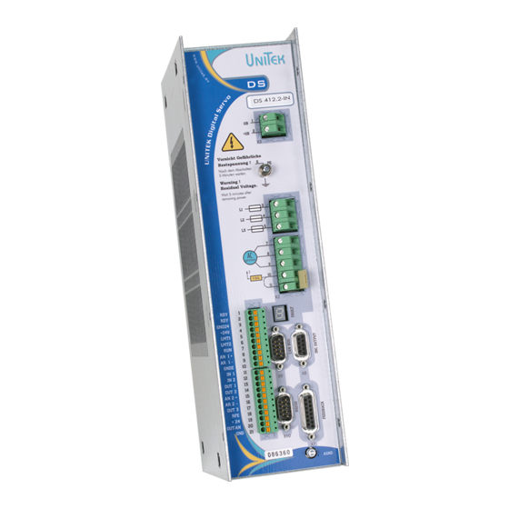
- Page 1 M A N U A L Digitale three-phase Servo Amplifier DS-400.2 for EC/AC-Servo Motors Hans-Paul-Kaysser-Straße 1 Ausgabe / Version 71397 Leutenbach-Nellmersbach 04/2019 - V01 Tel.: 07195 / 92 83 - 0 Fax: 07195 / 92 83 - 129 contact@unitek.eu www.unitek.eu...
-
Page 2: Table Of Contents
Basic information 1 Contents Basic information ........................3 History ..........................3 Further UNITEK products ....................3 Engineering instructions (MANUAL) .................. 3 Validity ..........................4 Designations and symbols ....................4 Scope of delivery ........................ 4 General product information ..................... 5 Application/build/features ....................6 Safety regulations ....................... - Page 3 Basic information Safety input RFE (rotating field enable) Stopp-Class 0 ............. 37 Digital outputs (open emitter) ..................38 Serial interface RS 232 ...................... 40 CAN-BUS ........................... 41 Resolver connection ......................42 Encoder TTL connection ....................43 SIN COS 1Vss CONNECTION ....................45 Rotor position encoder –...
-
Page 4: Basic Information
DS, DPC Commissioning - Troubleshooting Use all three MANUALs for the engineering, the installation, and the commissioning! CD (UNITEK-DOKU-SOFT) supplied with the delivery of the units. Online: www.unitek-online.eu The hardware MANUAL comprises warning and safety advices, explanations of standards, mechanical and electrical installation advices. -
Page 5: Validity
Warning! Important Dangerous electric fields Scope of delivery Divece DS405-x, DS412-x or DS420-x documentation DS400, NDrive, CD Unitek-Docu-Soft Connector plug Phönix 10pin. and 11pin. D-connector X7 15pin., X8 9pin In the shipping container Not in the delivery D-connectorr X9, X10 9pin. -
Page 6: General Product Information
Basic information General product information The digital 3-phase current servo amplifiers DS/DPC xxx as component (BDM) in combination with the synchronous servo motor (EC motor) or the asynchronous servo motor (ac motor) provide a drive solution (PDS) free of maintenance and with a wide dynamic control range. The drive displays the well-known good control characteristics of dc drives without the disadvantages of the carbon brushes' wear and the commutation limits. -
Page 7: Application/Build/Features
Basic information Application/build/features Application in machines and installations for all types of industrial use with a drive power of 13.5 kW under hard application conditions especially as 4Q-servo-drive - highly dynamic acceleration and braking cycles - a wide control range - a high efficiency - small motor dimensions - a uniform, accurate and smooth running... - Page 8 Basic information Features: EMC protected steel housing Shock and vibration-proof build Direct mains connection 230 V~ to 480 V~ Independent auxiliary voltage connection 24 V= Digital interfaces RS232, CAN-BUS (further option) Analog inputs, programmable differential inputs ...
-
Page 9: Safety Regulations
Basic information Safety regulations Electronic equipment is not fault proof! Caution - High voltage > 900V AC/DC ~/= Shock hazard! / Danger to life! Discharge time of the bus circuit > 4 min! Before installation or commissioning begins, this manual must be thoroughly read and understood by the skilled technical staff involved. - Page 10 Basic information The user must draw up a hazard analysis for his machine, vehicle, or installation. The user must ensure that in the event of: - device failure - incorrect operation, - loss of regulation or control the axis will be safely de-activated. It must also be ensured that the machines, equipment, or vehicles are fitted with device independent monitoring and safety features.
-
Page 11: Commissioning
Basic information 2.10 Commissioning The servo amplifiers DS4xx (BDM) are components of the electronic drive technology. They are functional only in connection with an electrical consumer (e.g. a motor). Their use is limited for industrial, commercial applications. When mounting the units into machines and installations the proper operation of the units may not be started until it is ensured that the machine, the installation, or the vehicle comply with the regulations of the EC machinery directive 2006/42/EG and the EMC guideline 2004/108/EG. -
Page 12: Safety Advices
Basic information 2.11 Safety advices Machinery directive The manufacturer of the machine or installation must draw up a hazard analysis for his product. He must make sure that any unpredictable movements do not cause damage neither to persons nor to property. Skilled personnel Hardware The skilled qualified personnel must feature a training and instruction for an assignment in the... -
Page 13: Intended Applications
Basic information 2.12 Intended applications The devices are designed as components (BDM) to control EC synchronous motors and ac asynchronous motors in stationary machines or installations. Any other type of application must be approved by the manufacturer. Protection rating IP20. It is only allowed to install the units in stationary switch cabinets or machine frames which are similar to switch cabinets. -
Page 14: Regulations And Guidelines
Basic information - in explosive environments - in environments with acrid fumes 2.13 Regulations and guidelines The device and its associated components can only be installed and switched on where the local regulations and technical standards have been strictly adhered to: EU Guidelines 2004/108/EG, 2006/95/EG, 2006/42/EG, 2002/96/EG EU Standards... -
Page 15: Risks
Basic information 2.14 Risks The manufacturer aims to keep the remaining risks emanating from the unit as low as possible by means of constructive, electrical, and software measures. In the field of drive engineering the following known remaining risks must be considered regarding the risks arising from machines, vehicles, and installations. -
Page 16: Technical Data
+10 % 50/60 Hz 24 V= ±10 % / 2A residual ripple < 10 % Auxiliary voltage connection EVL regenerating fuse Data Unit DS-405.2 DS-412.2 DS-420.2 Supply voltage - rated value 3x400 (480) Max. output voltage - rated value V~eff... - Page 17 Basic information Ambiant conditions Protection rating IP20, VGB4 Standards EN60204, EN61800, IEC60146 Protection rating Power protection class I (with PE firmly connected) Electronics protection class III (protection - low voltage) Over-voltage Class 2 (EN61800-5-1) Operating temperature range 0 to +45°C Extended operating temperature range from +45°C to +60°C performance reduced by 2 %/°C Storage and transport...
- Page 18 Basic information Blank page (for printing reasons) 04/2019 - V01 DS 400.2...
-
Page 19: Mechanical Installation
Mechanical Installation 3 Mechanical Installation Important advices Pay attention to the ESD advices. Blank mounting surface, no lacquer (EMC surface-to-surface contact) The unit must be safely protected in the switch cabinet against mist and water and the intrusion of metallic dust. Check the device for mechanical damage. -
Page 20: Dimensions Ds 405 - Ds 420
Mechanical Installation Dimensions DS 405 – DS 420 DS/DS-400-2-publi Size 2: DS405.xx bis DS420.xx Mounting depth: without connector 190 mm with connector max. 250 mm Fixing screws: M5x10 (recommended DIN 912) 04/2019 - V01 DS 400.2... -
Page 21: Dimensions - Accessories
Mechanical Installation Dimensions - accessories EMV-Filter Type Voltage Current Dimensions Weight HxBxT mm F250-V-B90-16 1x250 1x16 45x90x40 F400-V-B108-16 3x480 3x16 90x140x55 F400V-B150-25 3x480 4x25 130x180x80 Filters at high EMC requirements. In residential and commercial areas or unknown locations. Mount filter directly on the device. Bus filter and input filter capacitors are installed in the device. -
Page 22: Installation
Mechanical Installation Installation Enough space for the discharged ventilation air Power line signal line size 1 size 2 Supply air temperature 0 to max. 45°C DS-400-montage-2 In order to achieve good EMC values, it is recommended to use bright, unpainted mounting plates. -
Page 23: Electrical Installation
Ensure that the correct fuses have been provided for the power supply, the auxiliary voltage, and the external ballast resistors. Use a pre-charging circuit (UNITEK Inrush limiter). Power supply conductors and control lines must be routed separately from each other. -
Page 24: Circuit Diagram
Electrical installation Circuit diagram DS-400-blockbild-2-tms 04/2019 - V01 DS 400.2... - Page 25 Electrical installation Circuit diagram DS-400-blockbild-digi-1-5 DS 400-2 04/2019 - V01...
-
Page 26: Connection Diagram
Electrical installation Connection diagram Connections DS405.2, DS412.2, DS420.2 Mains voltage maximum 3x480V+10% Auxiliary voltage 24V= +24V GND24 Line protection Power on Inrush Limiter Detail X1-1 Page Safety circuit Ready Master X3-1 ext. regen connector GND24 resistor Limit Auxiliary Control 32 34 switch voltage Mains... -
Page 27: Connections Ds405.2, Ds412.2, Ds420.2
Electrical installation Connections DS405.2, DS412.2, DS420.2 For DC BUS with energy input and recovery module DC-BUS maximal 650= DC-BUS Auxiliary voltage 24V= input +24V GND24 output Modul X1-1 Safety Ready circuit X3-1 GND24 Limit Auxiliary Control switch voltage DC-BUS fuses END1 Limit Logic... -
Page 28: Connectors Ds405.2/Ds412.2/Ds420.2
Electrical installation Connectors DS405.2/DS412.2/DS420.2 DC Bus Earth Contact Main Power Motor Power CAN-BUSX9 CAN-BUSX9 Regen Resistor CAN-L CAN-L CAN-H CAN-H CAN-GND CAN-GND CAN-V+ CAN-V+ Encoder output input BTB/RDY Ready BTB/RDY Cannel A Cannel N Cannel B GND24 Cannel B Auxiliary voltage Cannel N Cannel A Select... -
Page 29: Emc
Electrical installation The devices adhere to the EU guidelines 2004/108/EC and the technical standard EN 61800-3 provided that the following conditions are observed: Mounting: The device is conductively mounted on a 500x500x5 mm bright mounting plate. The mounting plate must be connected to PE using a 10 mm² wire. The motor housing must be connected to PE using a 10 mm²... -
Page 30: Mains Connection
Electrical installation Mains connection Connection to earthed three-phase power supply system (TN-C mains supply). Asymmetrically earthed supply systems must be connected via an isolating transformer! Connection to the T-NC mains The max. supply voltage of 528 V~ must not be exceeded at any time (not even for short intervals)! Danger of damage! F1 = device protection... - Page 31 Electrical installation Note: For power supply systems without a PE conductor please note that the connection must be made via an isolating transformer. TT-mains Connection to the TT mains Asymmetric three or four conductor three-phase mains with direct earthing. Device PE via a ground connection Separating transformer Power line filter...
-
Page 32: Pre-Charging
The drive contactor K1 and the input rectifier may be damaged. A pre-charging unit must be installed. Pre-charging with inrush limiter The charging current is limited to < 10 A by means of the UNITEK Inrush Limiter. The power contactor K1 is switched on after a delay time. Attention: The drive contactor must not be switched under load. -
Page 33: Auxiliary Voltage Connection
Electrical installation Auxiliary voltage connection Mains potential-free auxiliary dc voltage 24 V= ±10 % / 2 A The auxiliary voltage - is galvanically connected with the logic voltage - is galvanically isolated from all internal supply voltages of the device - has internal regenerating fuses - has an EMC filter DSxx / DPCxx / BAxx... -
Page 34: Motor Connection
Electrical installation 4.10 Motor connection Only electronically commutating synchronous motors (brushless dc motors, EC motors, AC motors) must be used. These motors must be approved of by the manufacturer prior to any use. DS400 / DS-400-Motor-3 Cable Motor cable 3-core + protective earth, Connecting terminal X3:6 X3:7... -
Page 35: Ballast Circuit Ds405 / Ds412 / Ds420
Electrical installation 4.11 Ballast circuit DS405 / DS412 / DS420 X3:1 ext. regen resistor X3:2 F2-1 F2-2 X3:10 regen fuses X3:11 bridge with internal DSxx/BAxx regen resistor DS-BAx-DPC / E-DS-400-ballast-3 The energy arising during the braking operation is fed back into the dc bus circuit. The bus circuit Elkos can store only little energy. -
Page 36: Ballast - Dimensioning
Electrical installation 4.12 Ballast – dimensioning External ballast resistance Dimensioning Ballast resistance power Maximum value of the braking power P Ballast [W] = ___Pmax___ [W] = Jg x n x n K1 x K2 91 x t Motor torque and reduced load kgm²] max. -
Page 37: Control Connection
Control connection 5 Control connection Digital input 6 Opto-input Input voltage H-level (On) +10 bis +30 V L-level (Off) <+6 V Digital input (IP65) X1:5 Limit switch 1 END1/LMT1 (X1:E) X1:6 Limit switch 2 END2/LMT2 (X1:F) Input current Max. 7,5 mA X1:7 Enable FRG/RUN... -
Page 38: Safety Input Rfe (Rotating Field Enable) Stopp-Class 0
Control connection Safety input RFE (rotating field enable) Stopp-Class 0 Warning! If the input of the enable or of the rotating field enable are switched off, the drive is free of torque. The drive could move if there is no mechanical brake or block provided. The motor conductors are not dead. -
Page 39: Digital Outputs (Open Emitter)
Control connection Digital outputs (open emitter) Output voltage ON level max. +24 V= Digital output (IP65) OFF level <1 V= X1:13 Digital output 1 DOUT1 (X1:N) X1:14 Digital output 2 DOUT2 (X1:O) X1:17 Digital output 3 DOUT3 (X1:S) Output current F_AUSx Digital Output current... - Page 40 Control connection Analoge Eingang ±10 V 100k 1.5V +/- 1.36V analog inputs 100k 100nF Sollx REF150 100k DSxx/BAxx DSx-BAx-DPC/E-DS-400-Ana-1-2 Input Connection Basic function Voltage State Parameter AIN1+, AIN1- X1:8, X1:9 Speed command value +/- 10 V prog. AIN2+, AIN2- X1:15, X1:16 Current limit +/- 10 V prog.
-
Page 41: Serial Interface Rs 232
Control connection Serial interface RS 232 Via the serial pc interface RS232 the device is programmed and operated during commissioning. There is a software description in the Manual DS NDrive. The interface is galvanically connected with the device zero (GND/AGND). Connector at PC T2OU Stecker am PC... -
Page 42: Can-Bus
Control connection CAN-BUS The CAN-BUS is a digital connection to the CNC control. Optimum conditions are achieved with CNC controls and CAN components of LABOD electronic or CAN Open. Programming and operation by means of the control panel via the CAN-BUS. Interface complies with the standard ISO 11898. -
Page 43: Resolver Connection
Control connection Resolver connection Only for version RS The resolver is an absolute measuring system for a motor revolution. D-Stecker X7 D-connector X7 Motor-connector It is robust and not impaired by high Motor-Stecker DSxx/BAxx Resolver motor temperatures. Its build corresponds to a revolving transformer. -
Page 44: Encoder Ttl Connection
Control connection Encoder TTL connection Only for Version IN ITTL Incremental encoder (Encoder) with 2 counter tracks and 1 zero track plus 3 rotor position tracks. Counter D-connector X7 tracks with or without push-pull D-Stecker X7 DS xx/BAxx output VCC +5V VCC +5V Without a push-pull pulse a connecting adapter must be used. - Page 45 Control connection Adapter for INC- encoder with A,B,N channel without push-pull signals The device input for the incremental counter signals requires the push-pull counter pulses for a reliable side of motor INC-Encoder-Adapter side of device detection. Encoders without push-pull signals (e.g. position encoders) with different supply voltages are used for many simple applications.
-
Page 46: Sin Cos 1Vss Connection
Control connection SIN COS 1Vss CONNECTION Only for version SC Incremental encoder with 2 analog sinusoidal counter tracks and 1 zero track plus 2 commutating tracks. Differential inputs 1Vss. D-connector X7 D-Stecker X7 DS xx/BAxx Max. counting frequency 500 kHz VCC +5V VCC +5V The incremental encoder is galvanically... -
Page 47: Rotor Position Encoder - Connection Via A Bl-Tacho
Control connection Rotor position encoder – connection via a bl-tacho Only for version bl 3 rotor position encoder signals (Hall sensors) for the commutation; with or without a D-connector X7 D-Stecker X7 Adapter DS xx/BAxx brushless tacho. +15V +15V VCC +5V The rotor position encoder is galvanically connected with the device zero (GND). -
Page 48: X8 Ttl-Encoder Output Or Input (2)
Control connection 5.10 X8 TTL-Encoder output or input (2) The D-connector X8 is connected as input or output (default). Output X8 Pin 6 not connected or bridged with GND Input X8 Pin 6 bridged with +5 V (X8:1) VCC-CNT LBR 1 Inc-In D-connector X8 D-Stecker X8... -
Page 49: X8 As Ttl Encoder Output
Control connection 5.11 X8 as TTL Encoder output The encoder signals supplied by the motor (feedback) are available at the output of the D- connector X8 TTL encoder signals for the CNC control. The encoder output is internally isolated. The voltage is supplied via the encoder line from the CNC/PLC control. Voltage supply +5 V ±0.2 V. -
Page 50: Display
Control connection 5.12 Display The state "normal" is signalled by a bright green seven-segment display + decimal point (display of the state). The state "fault" is signalled by a bright red fault LED and the seven-segment display indicates the error no. The state "warning"... -
Page 51: Error Display On The Servo
Control connection 5.13 Error display on the servo The red LED "fault" is bright and the fault no. is indicated by the green seven-segment display. List of faults/errors Display Fault display on the Meaning controller NDrive BADPARAS Damaged parameter POWER FAULT Output stage error RFE FAULT Safety bus fault... -
Page 52: Warning Signals
Control connection 5.14 Warning signals The state "warning" is signalled by the flashing red fault LED and the seven-segment display indicates alternately the state and the warning no. List of warning signals Display Warning signals Meaning ID-Address Controller on the NDrive 0x8f WARNING_0 Device detection inconsistent... -
Page 53: Warranty
UNITEK undertakes no warranties for devices which have been modified for special applications. During the warranty period, UNITEK will, at its option, either repair or replace products that prove to be defective, this includes guaranteed functional attributes. UNITEK specifically disclaims the implied warranties or merchantability and fitness for a particular purpose.
Need help?
Do you have a question about the DS-405.2 and is the answer not in the manual?
Questions and answers