Table of Contents
Advertisement
Advertisement
Table of Contents

Related Manuals for KOHTECT qb701


Summary of Contents for KOHTECT qb701
- Page 1 KOHTECT qb701 LASER SHAFT ALIGNMENT SYSTEM USER’S MANUAL 2017...
-
Page 2: Table Of Contents
User’s Manual CONTENT General ........................4 Safety Precautions ....................4 Laser Safety Precautions ..................4 EC Declaration of conformity .................. 5 Technical Description ....................6 Designation ......................6 Misalignment Parameters ..................7 Specification and Features ..................8 System Package ....................9 System overview .................... - Page 3 User’s Manual Taking Readings. Auto Shooting mode ..............20 Readings quality assessment ................21 Editing of measurement points................21 Result Screen ..................... 22 Movable machine Adjustment ................23 Machines with Spacer Shaft .................. 24 Lock Feet Pair ..................... 25 Report file saving ....................
-
Page 4: General
Neither the NPP KOHTECT enterprise nor our authorized dealers are liable for the damages caused to machinery or equipment by use of the qb701 system. We carefully check text of this manual to eliminate errors, nonetheless there may be mistakes or inaccuracy involved. -
Page 5: Ec Declaration Of Conformity
User’s Manual EC DECLARATION OF CONFORMITY We, NPP KOHTECT, 167, Pogranichnaya str., 201, Nikolaev, Ukraine herewith declare that the following product: Shaft Alignment Tool qb701 has been designed and manufactured in accordance with: EMC DIRECTIVE 2004/108/EC as outlined in the harmonized norm for EN 61326-1:2013 Electrical equipment for measurement, control and laboratory use –... -
Page 6: Technical Description
User’s Manual TECHNICAL DESCRIPTION DESIGNATION qb701 alignment system (further as System) is designed for measurement of shaft axis misalignment of coupled machines, and calculation of movable machine adjustment required to eliminate misalignment that exceeds permissible tolerances; The machine alignment means adjustment of the relative position of two coupled machines (e.g. -
Page 7: Misalignment Parameters
User’s Manual MISALIGNMENT PARAMETERS Misalignment of any rotating machine is expressed in parallel (Offset) and angular (Gap) of the shafts. Most frequently in practice, both of them are present simultaneously. Different kinds of misalignment of axes are shown in Fig. 2. -
Page 8: Specification And Features
User’s Manual SPECIFICATION AND FEATURES Separation distance between measuring transducer units, up to 10 m Display control operating temperature range, -10..+55 degree C Measurement accuracy, 1%+0.01 Laser type: Visible red 635-670 nm, <1 mW Detector type: CCD, length 30 mm Display resolution, 0.01 or 0.001 mm, (1 or 0.1 mil ) -
Page 9: System Package
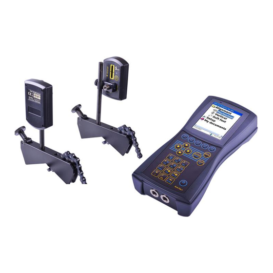
User’s Manual SYSTEM PACKAGE The System includes (Fig. 1): 1- AVV-711 display unit 2- two measuring transducer units – S, M 3- universal chain brackets for mounting of measuring units S, M 4- measuring tape 5- 120…240 Volts AC charger... -
Page 10: Mounting Transducers
User’s Manual MOUNTING TRANSDUCERS • Firmly tighten rods 1 into the shaft brackets 2. • Put thumb nut 3 into the bracket 2, then hook the chain 5 on the stud 4. • Firmly tighten the thumb nut 3. Shaft brackets with rods must be mounted at the same angular position. -
Page 11: Laser Beam Adjustment
User’s Manual LASER BEAM ADJUSTMENT • Loosen thumb nut and horizontally adjust transducer so the middle of the laser line is at the transducer’s window. • Slightly tighten thumb nut then vertically adjust laser line to the center of the transducer’s window. -
Page 12: Getting Started
User’s Manual GETTING STARTED COMMON CONTROL KEYS CONSIDERATION To turn ON/OFF display unit and transducers – press and hold the power button ~2 sec. In case the system hangs and device did not respond to any keys - press and hold the power button for ~10 sec, the system will be reset. -
Page 13: Setup Menu Items
User’s Manual SETUP MENU ITEMS – to setup date and time – to set device auto off delay in seconds. When set to 0 – auto off is disabled. – to install license file which enables + Function measurement functions. Press 9, browse... - Page 14 User’s Manual – to choose user interface language keys to choose language, then press – to switch qb701 into USB mass storage device mode. By default device can be connected to the PC via Microsoft Windows Mobile Device Center. USB mass storage device mode can be used as alternative.
-
Page 15: Horizontal Machine Alignment
User’s Manual HORIZONTAL MACHINE ALIGNMENT SHORT EXPLANATION Mount transducers on shafts Run Horizontal program Enter dimensions Set parameters. E.g. Measurement mode – clock type (9-12-3 o’clock positions) Turn shafts with transducers at first position 9 o’clock (90°). Press Start to take readings Turn shafts with transducers at second position 12 o’clock (180°). -
Page 16: Parameters
User’s Manual PARAMETERS In Main Menu run Horizontal program. Choose New Task. Machine dimensions / measurement setup screen Press key to start editing of the dimensions values Press key for parameters/key legend: Press - to toggle Spacer shaft Yes/No... -
Page 17: Tolerance Setup
User’s Manual Press - to toggle data input – LD transducer’s data / MD – manual data Press - to toggle angle input – IA use inclinometer / MA manual angle. Manual angle input used for vertical machines, when electronic inclinometer cannot be used. -
Page 18: Taking Measurements. Clock Mode
User’s Manual TAKING MEASUREMENTS . CLOCK MODE Press to edit dimensions. Set parameters and enter dimensions then press key to proceed. Turn shafts to first position – 9 o’clock (90°) 3 – clock mode – multipoint Press to take first reading. - Page 19 User’s Manual Press to take second reading. Turn shafts to third/last position – 3 o’clock (270°) Press to take third reading. When three reading are taken device will proceed to the result screen.
-
Page 20: Taking Measurements. Multipoint Mode
In multipoit mode readings can be collected at any shafts position minimum 3 up to 36 positions. qb701 is able to calculate misalignment after collecting at least 3 points within as little as 70 degree range. However always try to cover as wide shaft turn angle as possible. -
Page 21: Readings Quality Assessment
User’s Manual Auto shooting mode can be activated in both Clock mode and Multipoint mode. When device is in Multipoint mode and enough readings are collected – press to proceed to the result screen. When device is in Clock mode and three/four readings are taken device will automatically proceed to the result screen. -
Page 22: Result Screen
User’s Manual Edit Press key to activate edit mode mode keys to scroll over collected readings to delete readings key to quit edit mode (press until cursor points to the last measurement, then quit) RESULT SCREEN On the result screen device displays parallel and angular misalignment at the coupling and values of the required corrections in horizontal and vertical directions for movable machine. -
Page 23: Movable Machine Adjustment
User’s Manual MOVABLE MACHINE ADJUSTMENT To make adjustment in vertical direction transducers must be turned to 6 or 12 o’clock (0° or 180°) position. To make adjustment in horizontal direction transducers must be turned to 9 or 3 o’clock (90°... -
Page 24: Machines With Spacer Shaft
User’s Manual MACHINES WITH SPACER SHAFT Press to activate Spacer Shaft option. Procedure and options are the same as for Horizontal program. Enter machine dimensions. Collect readings. Make moveable machine correction. -
Page 25: Lock Feet Pair
User’s Manual LOCK FEET PAIR In some cases could be practical to swap movable machine. This function is applicable for Machines with and without Spacer shaft. Press key. Device will prompt to enter missed dimensions. Press key to lock feet pair. -
Page 26: Report File Saving
User’s Manual REPORT FILE SAVING Report file can be saved at any stage of alignment To save report file – press key in the result screen Reports can be saved to internal SD card or to thumb drive connected to USB host socket of the AVV-711 display unit... -
Page 27: Soft Foot
User’s Manual Press to edit file name, then press to save file SOFT FOOT Soft foot condition makes impossible proper machine alignment. So it should be eliminated prior to conduct alignment work. Soft Foot program intended for this purpose. - Page 28 User’s Manual Loosen first bolt fully Wait about 5 sec Press Tighten bolt firmly Press Loosen second bolt fully Wait about 5 sec Press Tighten bolt firmly Press Loosen third bolt fully Wait about 5 sec Press Tighten bolt firmly...
-
Page 29: Vertical Machine Alignment
User’s Manual VERTICAL MACHINE ALIGNMENT SHORT EXPLANATION Mount transducers on shafts Run Vertical program Mark on the machine three positions spaced by 90° (9-12-3 o’clock positions) Enter dimensions Set parameters. E.g. Tolerances. Turn shafts with transducers at first position 9 o’clock (90°). Press Start to take readings Turn shafts with transducers at second position 12 o’clock (180°). -
Page 30: Parameters
User’s Manual PARAMETERS In Main Menu run Vertical program. Choose New Task. Machine dimensions / measurement setup screen Press key to edit dimensions values Press key for parameters/key legend: Press - to toggle data input – LD transducer’s data / MD –... -
Page 31: Taking Measurements. Clock Mode
User’s Manual Multipoint mode – measurements may be taken at any minimum 3 up to 36 positions. After taking enough readings one should press to proceed to the result screen. For Vertical machines inclinometer data is unavailable, so angle value for each point should be entered manually, taking into account mentioned above positions conventions. -
Page 32: Result Screen
User’s Manual Arrow keys can be used to choose actual measurement position Turn shafts to second position – 12 o’clock (180°) Press to take second reading. Turn shafts to third/last position – 3 o’clock (270°) Press to take third reading. - Page 33 User’s Manual Keys legend can be invoked by Press key to toggle between parallel/shimming values screens. Shimming values Press key to choose plane (9-3 or 12-6) in which parallel correction will be performed. To make correction in 9-3 plane transducers must be placed at 9 or 3 o’clock position.
-
Page 34: Machine Correction @45
User’s Manual MACHINE CORRECTION @45 In order to exclude the need to turn the shafts when switching correction plane, transducers can be placed at one of 45° positions: 10:30, 1:30, 4:30, 7:30 o’clock. This option can be used on Horizontal and Vertical machines. -
Page 35: Charging Batteries
User’s Manual CHARGING BATTERIES The battery can be charged by means of USB type AC charger or via USB type charger PC/laptop USB port. connector Immediately after connecting charger to the display unit there are few seconds to change charge current - press and hold ON button for ~2sec until LED changes flash rate. -
Page 36: Firmware Upgrade
USB thumb drive – create the folder AvvUpd.ate 2. Copy firmware file Avv711Intall.cab to this folder 3. Remove USB thumb drive from PC/Laptop port and insert it to the qb701 USB host port. Press and hold key for ~2 sec to turn qb701 on. - Page 37 User’s Manual 7. Press key then to confirm replace of all existing files 8. Press key to choose NO, then press 9. Firmware upgrade will run. Once finished press to turn device...
-
Page 38: Firmware Upgrade Using Windows Mobile Device Center
1. Connect AVV-711 to PC via USB cable. Press and hold key for ~2 sec to turn qb701 on. Windows Mobile Device center will launch. Connect to qb701 and browse to the folder “Storage Card/LaserAlignment/AvvUpd.ate/” and paste there the firmware file Avv711Install.cab... - Page 39 User’s Manual 5. Press key then to confirm replace of all existing files 6. Press key to choose NO, then press 7. Firmware upgrade will run. Once finished press to turn device...
-
Page 40: Standard Tolerances Of Shaft Misalignment
User’s Manual STANDARD TOLERANCES OF SHAFT MISALIGNMENT This chapter provides the standards alignment tolerance of misalignment for standard industrial machinery with flexible coupling that can be used under condition only if existing in-house standards or the machine or coupling OEM have not given any blinding values, and must not be exceeded. -
Page 41: Delivery Set
User’s Manual DELIVERY SET № Description Note Control Display Unit Measuring Transducer Units S, M Brackets Frame Chains assembly Supporting Rods AC Charger, 100-240Volts Tape Measure 2m Carrying Case Operating Instructions Manual (on internal SD card) ConSpect Software (on internal SD card)
Need help?
Do you have a question about the qb701 and is the answer not in the manual?
Questions and answers