Table of Contents
Advertisement
Quick Links
Advertisement
Table of Contents

Related Manuals for Clayton Steam Master CSMG-15

Summary of Contents for Clayton Steam Master CSMG-15
- Page 1 Cover STEAM MASTER SERIES CSMG-15/30/40 USER MANUAL R027880B-20190603...
- Page 2 For your convenience, enter your unit’s specific model and serial number in the space below. The model and serial number are located on the right-hand side of the electronic controls cabinet. MODEL: _______________________ SERIAL NUMBER: _____________________...
-
Page 3: Safety Summary
SAFETY SUMMARY EMERGENCY STOP In the case of an emergency, immediately press the EMERGENCY STOP pushbutton (S101). Turn the main disconnect switch (S10), located directly below emergency stop pushbutton, to the OFF position. Turn off main fuel supply. HIGH PRESSURE VESSEL Heating section of the steam generator/fluid heater is under pressure when the unit is in operation. - Page 4 Generally, your Clayton Steam Generator, as delivered from Clayton, is covered for a storage period of three months. For storage periods that may exceed three months, follow the storage instructions described in the equipment documentation package.
-
Page 5: Important Information
IMPORTANT INFORMATION PLEASE READ THIS PAGE CAREFULLY 1. READ THIS INSTRUCTION MANUAL AND THE INSTALLATION MANUAL CAREFULLY BEFORE INSTALL- ING, OPERATING, OR SERVICING THE STEAM GENERATOR UNIT. KEEP ALL INSTRUCTIONS IN LEGIBLE CONDITION AND POSTED NEAR THE STEAM GENERATOR FOR REFERENCE BY OWNER AND SERVICE PERSONNEL. -
Page 6: Receiving And Unpacking
RECEIVING AND UNPACKING Your Clayton Steam Master Steam Generator arrives anchored to a shipping pallet. It is typically packaged in protective plastic wrap—unless otherwise specified (See below.). Properly-rated lifting equipment MUST be used to move your steam generator. IT IS YOUR RESPONSIBILITY TO INSPECT YOUR... -
Page 7: Overview Of Unit Features
Overview of Unit Features The following pages describe the controls and other features of the Clayton Steam Master. These pages are only a general overview. The controls and features may differ depending on the unit’s size and specifications. See page viii for description of unit features. - Page 8 The controls and features may differ depending on the unit’s size and specifications.
- Page 9 The controls and features may differ depending on the unit’s size and specifications.
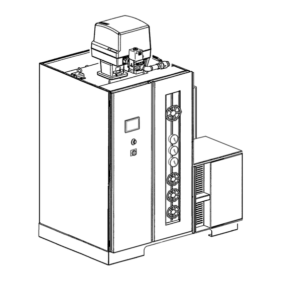
- Page 10 Description of Unit Features Gas Train, Main Gas Supply Gas Inlet, Main Compact Burner, Weishaupt Steam Outlet Exhaust Outlet OIU (Operator Interface Unit) Condensate Return, Steam Trap Economizer Drain Blowdown Drain Separator Exhaust Duct/Economizer Pump and Motor Assembly Heating Coil Water Inlet, Pump Feedwater Pressure Gauge Maintenance Drain Valve...
-
Page 11: Asme Conformance Statement
NBBI certification and UL compliance assures that a Clayton Steam Generator is reliable and capable of producing the high quality steam it was designed to deliver. All Clayton Steam Generators are built to conform to the rules and practices for safety and durability of the highest recognized regulatory authority. - Page 12 (electronic, mechanical, photocopy, recording, or otherwise) without written permission from Clayton Industries. The descriptions and specifications shown were in effect at the time this publication was approved for printing. Clayton Industries, whose policy is one of continuous improvement, reserves the right to discontinue models at any time, or change specifications or design without notice and without incurring any obligation.
-
Page 13: Specifications
SPECIFICATIONS Units of CSM-15 CSM-15-SE CSM-30 CSM-30-SE CSM-40 CSM-40-SE Measure- ment Boiler Horsepower Heat Input: Gas Btu / hr 619,907 590,735 1,239,815 1,181,471 1,653,086 1,575,294 Net Heat Output Btu / hr 502,125 502,125 1,004,250 1,004,250 1,339,000 1,339,000 Equivalent Output (From and at 212 °F lbs / hr 1,035 1,035... - Page 14 (This page intentionally left blank.) Specifications_CSM_a.fm 11/22/2018...
-
Page 15: Table Of Contents
Table of Contents Safety Summary ............................. i Important Information .......................... iii Receiving and Unpacking ........................iv Overview of Unit Features ............................ v ASME Conformance Statement ......................ix Specifications ............................xi Section 1 Using This Manual ......................1-1 General ........................1-1 Feedwater Treatment .................... - Page 16 3.1.11 Vacuum Created By Steam or Hot Water Cooling Down ........3-2 3.1.12 Water Hammer ....................3-2 3.1.13 Pre-stressed Springs ..................3-2 3.1.14 Electrical Parts ....................3-2 3.1.15 Chemicals ......................3-2 3.1.16 Loud Excessive Noise ..................3-2 3.1.17 Human Error ....................... 3-2 3.1.18 Automation ......................
- Page 17 Section 5 Troubleshooting ........................ 5-1 Water System ......................5-2 Fuel System - Gas-fired Machines ................5-3 Electrical System ......................5-4 Weishaupt Packaged Burner Unit ................5-5 Section 6 Periodic Maintenance ......................6-1 Feedwater Treatment ....................6-1 Daily Service ....................... 6-1 6.3.1 Record Operating/ Steam Pressure ..............
- Page 18 Feedwater Pump Relief Valve ..................7-7 7.3.1 Adjustment ......................7-7 Temperature Controllers (MTLC1, MTLC2) ..............7-7 7.4.1 Check Main Temperature Limit Controllers ............7-7 Operating Pressure Switch (OPS) Adjustment ............. 7-8 Limit Pressure Switch (LPS) Adjustment ..............7-8 7.6.1 Adjustment ......................7-8 Gas Pressure Switches ....................
-
Page 19: Section 1 Using This Manual
The machine overview includes a dis- cussion on the theory of operation of a Clayton Steam Generator. CAUTION paragraphs provide instructions for... -
Page 20: Feedwater Treatment
Feedwater Treatment Proper and adequate feedwater treatment must be used from the time your Clayton steam generator is commissioned. Suitable water treatment equip- ment should be installed before placing the steam generator into service. Daily treatment and care of the feedwater supply is the sole responsibility of the user. -
Page 21: Section 2 Description
General A reciprocating pump diaphragm displaces feedwa- ter through the discharge side of the check-valve The Clayton steam generator will deliver its housing into the heating coil. Corrosion-resistant rated output of 99 percent quality steam (containing springs, discs, and seats are used in the check-valve less than one percent moisture) per hour from 60°... - Page 22 Steam Master Instruction Manual OPTIONAL ECONOMIZER A– Steam Discharge Valve B– Coil Feed Valve C– Feedwater Pump D– Feedwater Valve E– Separator Drain Valve F– Coil Drain Valve Fig. 2-1. Water and Steam System (typical) 2.2.3.1 Main Temperature Limit Controller (MTLC2) This over-temperature safety controller (see Fig.
-
Page 23: Steam Separator
Section II–Description 2.2.3.2 Thermocouple sensor bottom of the separator. What results is “dry” steam being discharged from the steam separator outlet MTLC2 and MTLC1 each use one-half of a (A–Fig. 2-1). dual-element thermocouple sensor. The sensor is inserted in the coil steam discharge outlet. See Fig. The excess water in the separator is recircu- 2-2. -
Page 24: Steam Trap
Steam Master Instruction Manual 2.2.5 Steam Trap Control Devices The steam trap returns excess water from the 2.3.1 Group Motor Protectors (GMP) steam separator to the hot-well tank. Some trapping The group motor protectors function as a is necessary to ensure that a sufficient volume of 3-phase, manual, motor starter/protector for control feedwater is circulating through the heating coil and and protection of their respective motor(s). -
Page 25: Limit Pressure Switch (Lps)
Section II–Description Fig. 2-4. Wiring diagram for a standard step-down transformer Fig. 2-3. Wiring diagram for a standard step-down transformer 2.3.8 Variable Speed Drive (VSD) The VSD provides variable frequency input to 2.3.4 Limit Pressure Switch (LPS) the feedwater pump motor(s), dictating the rpm of This safety limit switch is connected in series the feedwater pump(s). - Page 26 Steam Master Instruction Manual (This page intentionally left blank.) Sect02_CSMG_b.fm 04/19/2019...
-
Page 27: Section 3 Safety Precautions
Section III SAFETY PRECAUTIONS GENERAL SAFETY the key from the switch. If you need to work on parts PRECAUTIONS without protective screens, make sure not to wear loose clothing such as ties, open coats, etc. Only A steam generator and its parts are based on authorized personnel should be present near the physical processes, each with typical characteristics generator. -
Page 28: Heavy Or Loose Parts
Steam Master Instruction Manual Fluids or gases under pressure can cause Parts not strong enough to support heavy severe skin or eye damage due to their impact when weights some parts can bend or break with flowing through fine openings. They can even enter overloads. -
Page 29: Automation
Potential unexpected automatic start ups can Only personnel who are properly trained to occur if equipment is not secured properly. A steam work on Clayton feedwater pumps should handle its generator and its parts can cause all of the safety maintenance and repair. -
Page 30: Fluid Under Pressure
Steam Master Instruction Manual Before performing electrical work on compact burner system, shut main gas supply valve(s). Purge Damage to heating coil, separator, and other gas from all gas lines. Purge gas from heating unit’s parts will result from moisture or fluid inside the combustion chamber. -
Page 31: Section 4 Operating Instructions
Fig. 4-1. The icons will be Clayton Steam Master steam generator. either active or inactive depending on the operator Your Clayton Steam Master offer two access level. The advanced-level screens require operating modes, auto mode and manual mode. -
Page 32: Start Mode
Steam Master Instruction Manual Fig. 4-2. Start up screen. Fig. 4-4. Firing in auto screen. The fill mode screen that displays is in Fig. The unit will start the light-off sequence. The 4-3. It displays a graphic depicting the fill rate and FIRING IN AUTO screen will display (Fig. -
Page 33: Easy Start
Manual mode operation requires the operator to be present and actively monitoring the unit throughout this period. Your Clayton Steam Master may be operated manually for maintenance, troubleshooting, and repair purposes. Manual mode operation enables the operator to dictate the fill rate and firing rate of Fig. -
Page 34: Manual Firing Mode
Steam Master Instruction Manual screen. A pop-up box will display where a new value can be entered. The firing rate remains fixed at the rate entered until it is changed. The unit may be transferred back to manual fill mode at any time during the manual firing mode by returning to the main menu and selecting the RUN TO FILL icon. -
Page 35: Intermittent Fill / Wet Lay-Up
NTERMITTENT A dry shut down should be performed Intermittent fill maintains a “wet” coil. This by Clayton service personnel or other operation is active when the unit is in wet lay-up. personnel who are thoroughly trained in Wet lay-up is used when the unit will be shut down Clayton steam generators. -
Page 36: Advanced-Level Screens
PID setpoint, and PID control output DVANCED EVEL CREENS Advanced-level screens are reserved for Clayton personnel/technicians Clayton authorized personnel. Advanced-level screens are password protected, which require user login from the main menu screen (See Fig. 4-1 on page 4-1.). -
Page 37: Calibration Screens
4.9.2 Calibration Screens steam temperature Delta-T, ramp release time, and The following calibration screens are Clayton stack temperature alarm setpoint can be entered on this screen. Technician level access. Fig. 4-17. Calibration Screen 1: machine hours, service Fig. -
Page 38: Alarm Screens
Steam Master Instruction Manual 4.10 A 4.11 M LARM CREENS AINTENANCE RAIN The maintenance drain screen is typically 4.10.1 Alarm Annunciation used for maintenance procedures, such as TDS This screen displays the alarm condition. The control. alarm condition must be corrected before pressing the RESET icon. -
Page 39: Section 5 Troubleshooting
Section V TROUBLESHOOTING NNUNCIATOR YSTEM The following chart lists the primary safety shutdown conditions together with the cause and remedial procedure to follow in the event a safety shutdown of the machine has occurred. Trouble Possible Cause Remedy Pump trouble Low NPSH to water inlet Check for a ruptured diaphragm in feedwater section of pump. -
Page 40: Water System
Steam Master Instruction Manual Trouble Possible Cause Remedy VSD overload VSD over current (ground fault) or exces- Check for and correct causes of sive current due to overload has caused the overload in the VSD circuit. The thermal or over current trip unit, in the GMP can be reset after the overload GMP, to secure the VSD and Burner. -
Page 41: Fuel System - Gas-Fired Machines
Section V–Troubleshooting Trouble Possible Cause Remedy Steam trap pressure gauge Steam trap closed. Ensure feedwater pump is discharging reads zero pressure at normal capacity. Blowdown valve partially open. Close Check for possible malfunctioning of steam trap. Machine overfired. Check temperature on separator tem- perature gauge. -
Page 42: Electrical System
Steam Master Instruction Manual 5.4 E LECTRICAL YSTEM WARNING Observe all warning and caution labels to avoid electrical shock when working with elec- trical components. Trouble Possible Cause Remedy Burner purge cycle fails to occur GPSL actuated. Reset GPSL. Check supply gas pressure. -
Page 43: Weishaupt Packaged Burner Unit
Section V–Troubleshooting Trouble Possible Cause Remedy Burner purge cycle fails to occur Modulating motor, safety shut-off Modulating motor must be in low- valve, ATS, or other upstream con- fire position. tacts open. Be sure gas valve (SSGV or MGV) (proof-of-closure valve) is not hung open. - Page 44 Steam Master Instruction Manual NOTES Sect05_CSMG_a.fm 11/26/2018...
-
Page 45: Feedwater Treatment
A manual bleed blowdown is used to control Periodic inspections and regularly scheduled dissolved solids and to remove suspended solids maintenance on the Clayton steam generator is and sludge. Manual bleed blowdown may be elimi- essential for maintaining its peak performance and nated from daily operation if an automatic bleed reliability. -
Page 46: Weekly Service
Steam Master Instruction Manual NITROGEN LAYUP– If unit is laid-up with a nitrogen blanket, verify pressure is maintaining 35 psig (240 kPa). Take appropriate action to rem- edy condition if a loss of pressure has occurred due to system leakage. Weekly Service 6.4.1 Steam Generator Unit Purge sludge settlement at the steam generator... -
Page 47: Flush Water Pump Heads And Columns
Section VI–Periodic Maintenance A constant steam pressure discharge must be quently. If drain cocks are plugged, remove cocks maintained under a steady load condition that will and use a stiff wire to dislodge sediment. (Water prevent burner modulation. To check the feed pres- pump may be operated and coil feed valve throttled sure, open the valve to the feed pressure gauge just to provide pressure to purge cock if not severely... -
Page 48: Check Main Temperature Limit Controllers (Mtlc)
Steam Master Instruction Manual 6.5.3.1 Steam temperature reading with steam e. Record the feedwater temperature read- generator in operation ing on the thermometer on or near the feedwater pump. a. Connect the test meter to the primary el- ement of the dual element thermocouple Alternatively, a feedwater temperature sensor. -
Page 49: Clean Strainers
OH alkalinity The pliability of the rubber inserts can be checked through the breather holes at the base of the surge chamber and discharge snubber housing. NOTE Review Clayton Industries a. Remove the top cover, right-side panel, Feedwater Treatment Reference... -
Page 50: Semi-Annual Service
Steam Master Instruction Manual ify the drain lines are clear of blockage for proper draining. See Section 7.2 adjustment and mainte- nance procedures. NOTE Increase maintenance intervals to three months on older feedwater relief valves. Fully open the coil feed valve after feedwater pump relief valve check is complete. -
Page 51: Replace Check-Valves
-Weishaupt- Installation nance shutdowns (See paragraph 7.2.3). and Operating Instructions Manual provided with your Clayton Steam Master unit. NOTE Feedwater pump diaphragms must Heating Coil Scale Removal be replaced more often (than 7,000... - Page 52 Steam Master Instruction Manual no outlet at the bottom of the container, NOTE fasten a fine mesh screen over the end of Larger containers maybe required if the hose and place that end of the hose severe scaling exists. Review this inside the container.
-
Page 53: Descaling The Machine
Section VI–Periodic Maintenance b. Add or remove water from the container until a steady circulation can be main- COIL FEED INTAKE SURGE VALVE tained through the system and back to the CHAMBER container, with about 4 – 5 inches (10 – 13 cm) of water remaining in the con- FEEDWATER tainer. -
Page 54: After Descaling Is Complete
Steam Master Instruction Manual e. Continue the circulation for 4–6 hours. A 6.8.3 After Descaling Is Complete longer circulation time is required if bub- bling still occurs in the discharge solution. Acid solution will burn face, arms, and other body parts. Carefully disconnect hoses to avoid NOTE spilling acid solution. - Page 55 Section VI–Periodic Maintenance NOTE Start the machine and blowdown the machine thoroughly four to five times (See Section 4.8. of Section IV.) before resuming normal operation. This will dislodge and remove much of the loosened scale. 6-11 04/22/2019 Sect06_CSMG_b.fm...
- Page 56 Steam Master Instruction Manual (This page intentionally left blank.) 6-12 Sect06_CSMG_b.fm 04/22/2019...
-
Page 57: Section 7 Component Maintenance
DO NOT OVERTIGHTEN. g. Replace feedwater pump compartment covers. Fig. 7-1. Remove covers for pump compartment. Fig. 7-2. Use of Clayton seat puller and seat driver 04/26/2019 Sect07_CSMG_b.fm... -
Page 58: Feedwater Pump Maintenance
Steam Master Instruction Manual Feedwater Pump Maintenance PUMP ASSEMBLY INTAKE/DISCHARGE CHECK-VALVE Avoid bodily injury. Always lock-out main electrical power to the machine to prevent accidental machine startup when repairing or performing maintenance on the machine. 7.2.1 Check-Valve Maintenance (See Fig. 7-3.) a. -
Page 59: Diaphragm Replacement
Install the diaphragm cap screw and washer. Torque cap screw to 30 ft-lb (41 • g. Install pumphead/check-valve assembly over the pumphead studs. h. Apply “Never-Seez” thread lubricant to each stud. Fig. 7-4. Use of Clayton seat puller and seat driver 04/26/2019 Sect07_CSMG_b.fm... - Page 60 Steam Master Instruction Manual 1. Check-valve Housing 12. Retaining Plate 21. Connecting Link Bearing 2. Standpipe 13. Washer 22. Crankshaft Bearing 3. Diaphragm Washer, Top 23. Crankshaft 14. Screw 4. Diaphragm 24. Check-valve Seat 15. Nut 5. O-ring Packing 25. Intake Spring 16.
-
Page 61: Pump Disassembly
Fig. 7-6. Use of Clayton seat puller and seat driver b. Replace the crankshaft (23) or the con- necting link (8), or both, if they are scored or damaged due to seized bearings. -
Page 62: Install High Strength Studs
Steam Master Instruction Manual b. Apply Loctite Bearing Mount-Grade B to b. Spray primer (Locquic “T” Primer) only the inside surface of the bearing hole on on the short threaded end of the cleaned the crankcase (9). Press the connecting stud. - Page 63 Section VII–Component Maintenance Feedwater Pump Relief Valve b. To raise the pressure adjustment, turn the adjusting screw clockwise. Similarly, to Excessive leakage from the relief valve will lower the pressure adjustment, turn the result in insufficient water to the heating coil and adjusting screw counterclockwise.
- Page 64 ONLY be within the operating range of the switch and in performed by Clayton Service or by accordance with Clayton prescribed switch setpoint Clayton-authorized service technicians. parameters. The switch has a fixed differential and will close and restart the burner when steam pres- sure drops about 8 psi (0.55 bar) below the OPS...
- Page 65 Section VII–Component Maintenance a. Remove clear cover from the switch to gain access to adjustable (yellow) dial (Fig. 7-10). b. Turn dial until the desired pressure set- point is aligned with the white line on the yellow dial face. c. Verify the switch operates as intended. d.
- Page 66 Steam Master Instruction Manual (This page intentionally left blank.) 7-10 Sect07_CSMG_b.fm 04/26/2019...
- Page 67 Steam Generator List of Parts Fig. 01A - Main Heating Section–SM15 ............A-2 Fig. 01B - Economizer Stack Outlet Kit–SM15 ..........A-4 Fig. 01C - Main Heating Section–SM30 ............A-6 Fig. 01D - Economizer Coil–SM30 ..............A-8 Fig. 01C - Main Heating Section–SM40 ............A-10 Fig.
- Page 68 Fig. 01A - Main Heating Section–SM15 HeatingSect_SM15_a.fm 04/30/2019...
- Page 69 FIG. 01A - Main Heating Section – SM15 04/30/2019 HeatingSect_SM15_a.fm...
- Page 70 Fig. 01B - Economizer Stack Outlet Kit–SM15 HeatingSect_SM15_a.fm 04/30/2019...
- Page 71 FIG. 01B - Economizer Stack Outlet Kit – SM15 04/30/2019 HeatingSect_SM15_a.fm...
- Page 72 Fig. 01C - Main Heating Section–SM30 HeatingSect_SM30_b.fm 12/05/2018...
- Page 73 FIG. 01C - Main Heating Section – SM30 12/05/2018 HeatingSect_SM30_b.fm...
- Page 74 Fig. 01D - Economizer Coil–SM30 HeatingSect_SM30_b.fm 12/05/2018...
- Page 75 FIG. 01D - Economizer Coil – SM30 12/05/2018 HeatingSect_SM30_b.fm...
- Page 76 Fig. 01C - Main Heating Section–SM40 A-10 HeatingSect_SM45_b.fm 04/30/2019...
- Page 77 FIG. 01C - Main Heating Section – SM40 A-11 04/30/2019 HeatingSect_SM45_b.fm...
- Page 78 Fig. 01D - Economizer Coil–SM40 (Sht 1 of 2) A-12 HeatingSect_SM45_b.fm 04/30/2019...
- Page 79 FIG. 01D - Economizer Coil –SM40 A-13 04/30/2019 HeatingSect_SM45_b.fm...
- Page 80 Fig. 02A - Steam Discharge and Separator Hookup—SM-15 A-14 Sep-Trap-PressMfld_SM153040_b.fm 04/30/2019...
- Page 81 FIG. 02A - Steam Discharge and Separator Hookup — SM-15 A-15 04/30/2019 Sep-Trap-PressMfld_SM153040_b.fm...
- Page 82 Fig. 02B - Steam Discharge and Separator Hookup—SM-30/40 A-16 Sep-Trap-PressMfld_SM153040_b.fm 04/30/2019...
- Page 83 FIG. 02B - Steam Discharge and Separator Hookup — SM-30/40 A-17 04/30/2019 Sep-Trap-PressMfld_SM153040_b.fm...
- Page 84 Fig. 02C - Steam Trap and Control Valve Hookup Item Part No. Description Qty. 0016601 VALVE, Angle, 3/8 in., 6000# ........2 0044836 VALVE, Check, in-line, 3/8 in........1 0019348 VALVE, Globe, 1 in., 800# ........3 0019929 VALVE, Globe, 3/4 in., 800# ........3 0020001 VALVE, Globe, 1/2 in., 800# ........
- Page 85 Fig. 02D - Safety Relief Valve Hookup FIG. 02D - Safety Relief Valve Hookup A-19 04/30/2019 Sep-Trap-PressMfld_SM153040_b.fm...
- Page 86 Fig. 02E - Pressure Indicating System A-20 Sep-Trap-PressMfld_SM153040_b.fm 04/30/2019...
- Page 87 FIG. 02E - Pressure Indicating System A-21 04/30/2019 Sep-Trap-PressMfld_SM153040_b.fm...
- Page 88 Fig. 04A - Feedwater Pump Hookup–C1 Item Part No. Description Qty. UH30824 VALVE, Relief, 1/2 in., 275 psi (See Fig. 07 for details.) .... 1 UH23304 VALVE, Check, 1 1/4 in. (See Fig. 06 for details.) ..... 1 UH27215 CHAMBER ASSY, Intake Surge ..........1 UH24615 SNUBBER ASSY, Discharge, 300 psi ........
- Page 89 Fig. 04B - Feedwater Pump Hookup–C2 Item Part No. Description Qty. UH30824 VALVE, Relief, 1/2 in., 275 psi (See Fig. 07 for details.) .... 1 UH23304 VALVE, Check, 1 1/4 in. (See Fig. 06 for details.) ..... 1 UH27215 CHAMBER ASSY, Intake Surge ..........1 UH24615 SNUBBER ASSY, Discharge, 300 psi ........
- Page 90 Fig. 05A - Pump Assy–C1 A-24 PumpHkup-C1-C2_parts_a.fm 03/05/2019...
- Page 91 FIG. 05A - Pump Assy – C1 A-25 03/05/2019 PumpHkup-C1-C2_parts_a.fm...
- Page 92 Fig. 05B - Pump Assy–C2 A-26 03/05/2019 PumpHkup-C1-C2_parts_a.fm...
- Page 93 FIG. 05B - Pump Assy – C2 A-27 PumpHkup-C1-C2_parts_a.fm 03/05/2019...
- Page 94 Fig. 06 - Check Valve Item Part No. Description Qty. UH21728 VALVE, Check, 1 1/2 in., 350# ........ Ref. UH23304 VALVE, Check, 1 1/4 in., 300# ........ Ref. UH30530 VALVE, Check, 1 1/2 in., 350# ........ Ref. UH12797 . CAP ................ 1 0016547 .
- Page 95 SWITCH, Pressure, 12.0 in. – 60.0 in. w.c., ..1 - - - ACTUATOR, Gas Valve, P.O.C., SKP25.011U1 . 1 GML-A4-4-6, Dungs 266947 (Clayton equivalent part no.: 0039296) - - - VALVE, Solenoid, 3/4 in., 120v / 60Hz, Asco, ..1 - - - BODY, Gas Valve, 3/4 in., VGG10.204U ...
- Page 96 Fig. 13 - Electrical Control Box FIG. 13 Electrical Control Box A-30 ControlBox_CSM_a.fm 11/20/2018...
- Page 97 Fig. 18 - Separator High Level Alarm Kit Item Part No. Description Qty. 0038294 SENSOR, Conductance, water level ......1 0038263 PROBE, Sensor, conductance ........1 0039202 CONTROL, Liquid Level, octal ........1 E-STOP PUSHBUTTON INSIDE LEFT DOOR FIG. 18 Separator High Level Alarm Kit A-31 SHLA_a.fm 02/08/2019...
- Page 98 (This page intentionally left blank.) A-32 Blank_Left.fm 08/16/2017...
- Page 99 Feedwater Skid Option List of Parts Fig. 01 - Vertical Hotwell ..................B-2 Fig. 02 - Water Softener Plumbing Hookup ............B-2 Fig. 03 - Water Level Indication and Control ............B-3 Fig. 04 - Water Temperature and Blowdown Tank Hookup ......B-3 Fig. 05 - Sparger Tubes–Water Heating ............B-4 Fig.
- Page 100 25–75 bhp Feedwater Skid Option Fig. 01 - Vertical Hotwell Table 1 1 UH40252 Hotwell and Base-Vertical, 50 bhp 2 0030484 Valve, Ball, 1 1/2 in. 0030485 Valve, Ball, 2 in. Fig. 1 - Vertical Hotwell Fig. 02 - Water Softener Plumbing Hookup Optional Equipment Table 2 1 0040723...
- Page 101 25–75 bhp Feedwater Skid Option Fig. 03 - Water Level Indication and Control 0038263 - Probe, 0036203 - Valve, Conductance, 4 1/2 in. Gauge Glass, Top 0038294 - Sensor, Water Level 0037074 - Gauge, Glass, Level 0038581 - Box, 0037744 - Receptacle, Receptacle, 3-prong, GFCI...
- Page 102 25–75 bhp Feedwater Skid Option Fig. 05 - Sparger Tubes–Water Heating Table 4 1 UH32041 Tube Assembly, Sparger 2 0029882 Valve, Check, 1 in. 3 0020001 Valve, Globe, 1/2 in. 4 0043175 Valve, Check, 1/2 in. 5 0038297 Valve, Solenoid, 1/2 in. * 6 0038194 Valve, Ball, 1/2 in.
- Page 103 25–75 bhp Feedwater Skid Option Fig. 07 - Circulation Pump Hookup - TDS System Fig. 08 - Booster Pump Hookup Table 7 1 0037864 Gauge, Pressure, 2 1/2 in., 0 – 60 psi Table 6 2 0030491 Tube, Syphon, Loop, 1/4 in. 1 0033793 Valve, Ball, 3/4 in., stainless steel 3 0003440...
- Page 104 25–75 bhp Feedwater Skid Option (This page intentionally left blank.) FeedwtrSkid_VHtwl_25-75bhp_a.fm 11/26/2018...
- Page 105 PERIODIC MAINTENANCE LOG MODEL: Refer to instruction manual for maintenance procedure details. SERIAL NUMBER: It is owner's responsibility to ensure proper care and maintenance of their unit(s). Service work and replaced parts may be noted on far left column and on the reverse side. Some of the items described may not apply to each model.
- Page 106 R027906A-2018.10.22...
- Page 107 NOTES...
- Page 108 Steam Generator Instruction Manual (This page intentionally left blank.)
- Page 110 Back Cover 17477 Hurley Street, City of Industry, California 91744-5106, USA Phone: +1 (626) 435-1200 Fax: +1 (626) 435-0180 Internet: www.claytonindustries.com Email: sales@claytonindustries.com...
Need help?
Do you have a question about the Steam Master CSMG-15 and is the answer not in the manual?
Questions and answers