Advertisement
INSTALLER'S
GUIDE
ALL phases of this installation must comply with
NATIONAL, STATE AND LOCAL CODES
Models:
BAYEVAC05BK1A
BAYEVAC05LG1A
BAYEVAC08BK1A
BAYEVAC08LG1A
BAYEVAC10BK1A
IMPORTANT - This Document is customer property and is to remain with this unit. Please return to service information
pack upon completion of work.
Table of Contents
Section 1. Safety Information .......................................................................................................1
Section 2. General Information .....................................................................................................2
Section 3. Heater Assembly Labeled ...........................................................................................2
Section 4. Heater Selection...........................................................................................................3
Section 5. Adjust Heater ...............................................................................................................5
Section 6. Install Heater ................................................................................................................7
Section 7. Tables ..........................................................................................................................12
Section 8. Sequence of Operation .............................................................................................14
© 2012 Trane
BAYEVAC10LG1A
BAYEVBC15BK1A
BAYEVBC20BK1A
BAYEVAC10LG3A
BAYEVBC15LG3A
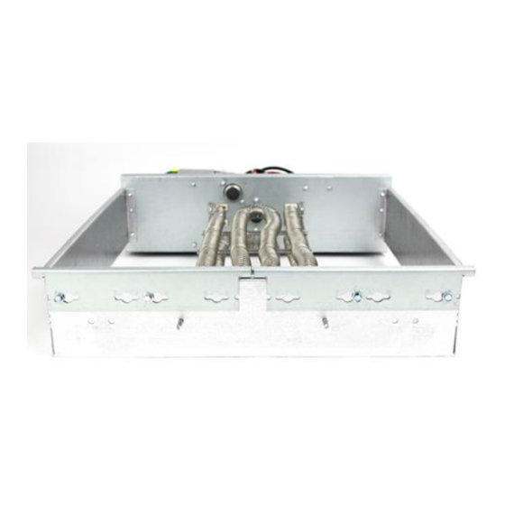
Supplementary
Electric Heaters
for Air Handler Installations
Section 1. Safety Information
L
!
SAFETY HAZARD!
This information is intended for use
by individuals possessing adequate backgrounds of electrical
and mechanical experience. Any attempt to repair a central air
conditioning product may result in personal injury and/or property
damage. The manufacturer or seller cannot be responsible for the
interpretation of this information, nor can it assume any liability in
connection with its use.
!
L
HAZARDOUS VOLTAGE!
power, including remote disconnects before servicing. Follow
proper lockout/tagout procedures to ensure the power can not
be inadvertently energized. Failure to disconnect power before
servicing could result in death or serious injury.
L
!
LIVE ELECTRICAL COMPONENTS!
stallation, testing, servicing, and troubleshooting of this product,
it may be necessary to work with live electrical components.
Failure to follow all electrical safety precautions when exposed to
live electrical components could result in death or serious injury.
L
!
SAFETY HAZARD!
Sharp Edge Hazard. Be careful of
sharp edges on equipment or any cuts made on sheet metal while
installing or servicing. Personal injury may result.
18-GJ09D1-5
WARNING
WARNING
Disconnect all electric
WARNING
During in-
CAUTION
10/12
Advertisement

Subscribe to Our Youtube Channel
Related Manuals for Trane BAYEVAC05LG1A


Summary of Contents for Trane BAYEVAC05LG1A
-
Page 1: Table Of Contents
Section 1. Safety Information .......................1 Section 2. General Information .....................2 Section 3. Heater Assembly Labeled ...................2 Section 4. Heater Selection......................3 Section 5. Adjust Heater .......................5 Section 6. Install Heater ........................7 Section 7. Tables ..........................12 Section 8. Sequence of Operation .....................14 © 2012 Trane 10/12... -
Page 2: Section 2. General Information
INSTALLER'S GUIDE Section 2. General Information This electric heater accessory is designed to provide power directly to the air handler from the accessory heater's power supply, eliminating the need for addi- tional circuits. The power and control wiring each use a single wire harness to connect the heater and the air handler. -
Page 3: Section 4. Heater Selection
INSTALLER'S GUIDE Section 4. Heater Selection Determine which heater best fits your application needs. In addition to electrical considerations, you must know your cabinet size and the range of heaters which fit that cabinet. 4.1 Air Handler Model Number Matrix Step 1 - Measure your cabinet and use the Air Handler Model Number Matrix to determine your cabinet size. - Page 4 INSTALLER'S GUIDE Step 2 - Use the Heater Model Number Matrix to de- termine which heaters will fit in your cabinet and to determine if you will have to modify the heater to fit the cabinet. Electric Heat Model Number Digit Example Brand...
-
Page 5: Section 5. Adjust Heater
INSTALLER'S GUIDE Section 5. Adjust Heater STEP 1 - Position Width Adjustment Brackets. Two Width Adjustment Brackets are located at the Width Adjustment Brackets back of the heater assembly. The heater comes (two per unit) sized for the smallest cabinet it will fit in. For this example our heater fits cabinets A, B, and C. - Page 6 INSTALLER'S GUIDE STEP3 - Attach Retainer Tabs and Edge Guard Note: For A cabinet widths, only the right side retainer tab must be installed. Add the Retainer tabs using the screws provided (both tabs and screws are located in the documentation packet).
-
Page 7: Section 6. Install Heater
INSTALLER'S GUIDE Section 6. Install Heater STEP 1 - Remove Heater Compartment Panel. Heater Compartment Panel Breaker Cover STEP 2 - Disconnect & Dispose of Pigtail Harness. Cut the wire tie that is holding the pigtail harness. Unplug and dispose of pigtail harness. Wire Tie Pigtail Harness... - Page 8 INSTALLER'S GUIDE STEP - 4 Lock Retainer tabs. Note: Retainer tabs are used to secure the heater Retainer inside of the heater compartment. Slide retainer tab into recess in air handler cabinet. Tighten screws to hold tab securely. Repeat actions to secure the other tab. Filler Note: For A cabinet widths, only the right side Plate...
- Page 9 INSTALLER'S GUIDE STEP 8 - Connect high voltage wiring Factory wiring Field wiring Connect the wiring to the lugs on the breaker models or to the terminal block on the lug models as illustrated. Connect the ground wire to the ground lug. Connect the 3-pin plug on the heater to the 3-pin plug in the air handler case.
- Page 10 INSTALLER'S GUIDE STEP 10 - Connect low voltage wiring. Connect the low voltage harness to Electric Heat Con- trol as shown. Low Voltage Harness STEP 11 - Place Wiring Diagram. Attach the wiring diagram, included in the documenta- tion packet, to the back of the heater compartment panel.
- Page 11 INSTALLER'S GUIDE Note: Breaker models only. STEP 12 - Remove breaker cover. Remove 5/16 hex screw on back of breaker cover Remove and discard the two piece breaker cover from the heater compartment panel. DI SC O US IN CL IN G ilu re L EL...
-
Page 12: Section 7. Tables
INSTALLER'S GUIDE Section 7. Tables Minimum Heating Airflow Settings MINIMUM HEATER AIRFLOW CFM - HEATER MATRIX BAYEVAC05BK1AA BAYEVAC08BK1AA BAYEVAC10BK1AA MODEL NO. BAYEVAC05LG1AA BAYEVAC08LG1AA BAYEVAC10LG1AA BAYEVAC10LG3AA BAYEVCB15LG3AA BAYEVBC15BK1AA BAYEVBC20BK1AA BAYEVCC25BK1AA TAM8A0A24V21CB 638/713 638/900 675 1 /900 600/713 TAM8A0B30V21CB 723/808 723/1020 765/1020 680/808 765/1063 850/1105... - Page 13 INSTALLER'S GUIDE Important: The BAYEV* electric heat accessory may include up to a combination of three 30 and/or 60 amp circuit break- ers to provide an electrical disconnect for service personnel that is intended to help protect internal electrical components in the event of a short circuit or ground fault.
-
Page 14: Section 8. Sequence Of Operation
INSTALLER'S GUIDE Section 8. Heater Operation 8.1 TAM7 Heater Operation 8.3 TAMG Heater Operation Electric Heat Electric Heat R-W contacts close on the comfort control sending R-W contacts close on the comfort control sending 24VAC to W1 of the AFC. 24VAC to W1 of the AFC. - Page 15 INSTALLER'S GUIDE Page 15...
- Page 16 Trane Since the manufacturer has a policy of continuous product and product 6200 Troup Highway data improvement, it reserves the right to change design and specification Tyler, TX 75707 without notice.
Need help?
Do you have a question about the BAYEVAC05LG1A and is the answer not in the manual?
Questions and answers