Table of Contents
Advertisement
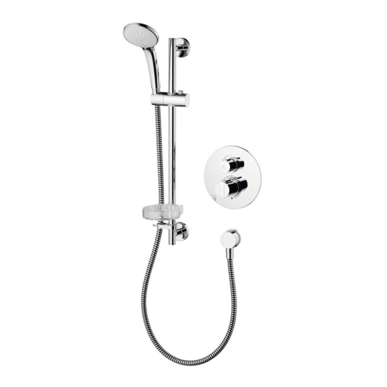
Thermostatic Built-In Shower Valves
Low profile valves suitable for slim duct systems
Built-in dual-control thermostatic shower valves in this product range are:
A5877AA Circular escutcheon with on/off flow control
A5878AA Square escutcheon with on/off flow control
A5879AA Circular escutcheon with 3 function diverter (to bath, off, or shower)
A5880AA Square escutcheon with 3 function diverter (to bath, off, or shower)
A5958AA Shower pack: flow control, circular escutcheon, 3 function kit & wall elbow
A5959AA Shower pack: flow control, square escutcheon, 3 function kit & wall elbow
BEFORE CONNECTION, FLUSH WATER
THROUGH PIPEWORK TO REMOVE ALL
DEBRIS ETC. WHICH COULD DAMAGE
THE VALVE MECHANISM
Installation Instructions
EASYBOX SLIM
IMPORTANT
INSTALLER
After installation please pass
this instruction sheet to user
Advertisement
Table of Contents

Related Manuals for Ideal-Standard Easybox Slim Series

Summary of Contents for Ideal-Standard Easybox Slim Series
- Page 1 Installation Instructions Thermostatic Built-In Shower Valves EASYBOX SLIM Low profile valves suitable for slim duct systems Built-in dual-control thermostatic shower valves in this product range are: A5877AA Circular escutcheon with on/off flow control A5878AA Square escutcheon with on/off flow control A5879AA Circular escutcheon with 3 function diverter (to bath, off, or shower) A5880AA Square escutcheon with 3 function diverter (to bath, off, or shower) A5958AA Shower pack: flow control, circular escutcheon, 3 function kit &...
- Page 2 58 - 68 Ø185 40 - 50 47 - 57 G 1/2 G 1/2 G 1/2 G 1/2 63 - 73 Inlets & Outlets are threaded G1/2“. The escutcheon plate can float 10mm between min & max markers thus per- mitting mounting depth to vary.
- Page 3 30-65 G 1/2 G 1/2 G 1/2 148 82 Ø128 5-40 G 1/2 Valve-box dimensions with OPTIONAL legs fitted max 313 Ø56 Ø56 Ø56 Ø56 G1/2 Shower kit supplied with circular Shower kit supplied with square escutcheon product A5958AA escutcheon product A5959AA For guidance on how to install the shower kit, please refer to the sepa- rate instructions provided with the kit.
-
Page 4: Table Of Contents
TABLE OF CONTENT 1 INTRODUCTION ..................5 2 SUPPLY CONDITIONS ................6 3 WATER REGULATIONS ................7 4.0 PRE-INSTALLATION NOTES: ..............8 4.1 OVERVIEW OF KITS 1 & 2 ..................... 8 4.2 KIT-1 MOUNTING DEPTH CONTROL ................8 4.3 MOUNTING OPTIONS, QUICK OVERVIEW ..............10 4.4 WALL TYPES, QUICK OVERVIEW................ -
Page 5: Introduction
The fittings covered by these instructions should be installed in accordance with the Water Regulations published in 1999*. Ideal Standard strongly recommends that these fittings are installed by a professional fitter. *A guide to the Water Supply (Water Fittings) Regulations 1999 and the Water Byelaws 2000, Scotland is published by WRAS (Water Regulations Advisory Scheme) Fern Close, Pen-y-Fan Industrial Estate, Oakdale, Newport, NP11 3EH. -
Page 6: Supply Conditions
2 SUPPLY CONDITIONS Table 1 Conditions of use for Type 2 valves BSEN1111 BSEN1287 Operating pressure range: High Pressure Low Pressure Maximum static pressure 10 bar 10 bar Flow pressure hot and cold 0.5 to 5.0 bar 0.1 to 1.0 bar Hot supply temperature 55 to 65 °C 55 to 65 °C... -
Page 7: Water Regulations
3 WATER REGULATIONS CATEGORIES OF RISK The water regulations published in 1999* take a new approach to backflow in that they look at different categories of risk. The installer must assess the risk from the various categories of fluid in adjacent appli- ances before determining the level of backflow protection required for a particular installation. -
Page 8: Pre-Installation Notes
4.0 Pre-installation notes: This installation instruction covers two main products types (both dual control): • Products with integral on/off flow control: A5877AA, A5878AA, A5958AA, & A5959AA. The temperature and the flow rate of the water can be adjusted using the two control handles on the valve. - Page 9 4.2 Kit-1 mounting depth control cont’ Effectively, the escutcheon plate can float 10mm, between the MIN & MAX (markers on the valve-box) thus permitting the mounting depth to vary by 10mm. 68 Max 58 Min Valve-box shoulder Max shroud Min shroud exposure exposure Cosmetically, when the escutcheon plate is...
-
Page 10: Mounting Options, Quick Overview
4.3 Mounting options, quick overview These products can be mounted using one (or a combination) of these 3 methods: Directly through the valve-box using the 4 corner slots onto a solid surface. This method does not allow for any depth adjustment. NOTE: All fixing methods utilise the 4 slots positioned in the... -
Page 11: Wall Types, Quick Overview
4.4 Wall types, quick overview These built-in products are designed for easy installation into most common wall types. These low profile valves are especially suitable for slim duct systems where the minimum wall cavity depth can be as little as 45mm. •... -
Page 12: Kit-1 Description
4.6 Kit-1 description The built-in valve-box is supplied with a plaster guard (protective cover) fitted as shown. The plaster guard prevents debris entering into the valve-box during installation. Additionally, the plaster guard also serves as an aid to levelling the valve-box whilst mounting onto a wall or panel. OBSERVE ORIENTATION OF VALVE-BOX, SEE 4.5. -
Page 13: Valve-Box Sealing System
4.7 Valve-box sealing system The built-in valve-box is designed with an extensive sealing system to prevent water penetration in two ways: Firstly, any trickles of water resulting from a minor leak inside the valve-box are prevented from entering into the wall cavity. Secondly, any water spray from the shower area is prevented from entering the valve-box. Fleece mat: is bonded between the wall &... -
Page 14: Installation Guide - Kit.1
5.0 Installation guide – kit.1 The thermostatic mixing valve must be installed in such a position that maintenance of the TMV and its valves and the commissioning and testing of the TMV can be undertaken. IMPORTANT BEFORE CONNECTION, FLUSH WATER THROUGH PIPEWORK TO RE- MOVE ALL DEBRIS ETC. -
Page 15: Mounting Methods
Water supply pipes Water supply pipes can be from any direction. Where supplies are provided from above, this normally permits better drain down of pipe-work. Pipe-work should be secured to the wall or panel using suitable fixing clips. DO NOT apply heat near this product. Heat generated by soldering could damage plastic parts and seals Suitable pipe connectors All 4 connections to this product are threaded G1/2”... -
Page 16: Using Optional Adjustable Fixing Legs (Method C)
Method B: cont. Attaching the mounting bracket to either top or bottom of the valve-box permits the product to be secured to a timber noggin (horizontal) in a partition wall. Alternatively, attach the bracket to either side of the valve-box to utilise a nearby timber stud (vertical) for fixing. -
Page 17: Mounting Valve-Box Into A Solid Wall
5.4 Mounting valve-box into a solid wall Before commencing, decide on which installation method to adopt from the two detailed below. Mark the wall at the desired location for the valve-box. Decide on preferred mounting option (see 4.3). Note: before mounting, it may be easier to fit pipe connectors to the valve-box (see 5.1). - Page 18 5.4 Mounting valve-box onto a solid wall, cont’ Cavity, either chased-out brickwork or timber studs Either tiled plaster board Solid wall or panelling system Use suitable support- Observe depth ing washers under the screw heads Mounting option A (direct) through the valve-box using the 4 corner slots Note: using mounting option A, (direct) provides the shallowest cavity depth, but does not permit any depth adjustment.
-
Page 19: Mounting Valve-Box Into A Pre-Fabricated Pod Wall
5.5 Mounting valve-box into a pre-fabricated pod wall These products can be installed into a modern pre-fabricated pod style bathroom. The valve-box can be mounted into the pod wall from the rear during the pod construction. Note: before mounting, it may be easier to fit pipe connectors to the valve-box (see 5.1). Typically, a pod wall is constructed with vertical steel members (40mm “U”... -
Page 20: Mounting Valve-Box Into A Panel
5.6 Mounting valve-box into a panel Recommended panel thickness should be in the range 14.5 to 26mm. Cut large hole in the panel (see 5.4) at the desired location for the valve-box. Decide on preferred mounting option (see 4.3). Two mounting methods are discussed below. -
Page 21: Mounting Valve-Box Into A Timber Stud Wall
5.7 Mounting valve-box into a timber stud wall These products can be installed into a modern timber stud construction partition wall. The mounting bracket supplied (option B) can be attached to any side of the valve-box (see 4.3 & 5.2). This enables the valve-box to be secured to either a timber stud (vertical on either side) or to a timber noggin (horizontal, below or above the valve-box). - Page 22 5.7 Mounting valve-box into a timber stud wall, cont Mounting (Typical dimensions are given here, for guidance only). bracket Stud Stud Plasterboard 45 min 12,5 cavity Tiles 8-10 Adhesive 2-3 Observe depth Plan view showing valve-box installed into partition wall, using mounting bracket. Direct mounting Alternatively, the valve-box can be mounted directly using the corner slots.
-
Page 23: Completing Pipe-Work
5.8 Completing pipe-work The valve-box should now be securely mounted in the wall or panel at the desired location. If not already done so, fit connectors to the valve-box, see 5.1. Remember one outlet can be closed off using the blanking plug (see 4.6). - Page 24 Basic installation example showing thermostatic shower valve with integrated “flow control” connected to a single outlet slide bar shower kit. Slide bar kit with handspray and hose As illustraded, top outlet used & bottom outlet blanked off. Wall outlet elbow to hose Alternative, bottom Cold water outlet used &...
- Page 25 Two outlet example showing thermostatic shower valve with integrated “diverter” connected to slide bar shower kit & overhead shower. Overhead shower Slide bar kit with handspray and hose As illustraded, both top & bottom outlets used. Wall outlet elbow to hose Cold water Hot water Mixed water...
- Page 26 Two outlet example showing thermostatic shower valve with integrated “flow control” connected to a slide bar shower kit & overhead shower via external diverter. Diverter has one inlet & two outlets. Slide bar kit with Overhead shower handspray and hose As illustraded, top outlet used &...
- Page 27 Three outlet example showing thermostatic shower valve with integrated “diverter” connected to a slide bar shower kit, overhead shower & body jets via an external diverter. Diverter has one inlet & two outlets. Overhead shower External diverter Slide bar kit with handspray and hose As illustraded, both Body jets...
- Page 28 Three outlet example showing thermostatic shower valve with integrated “diverter” connected to a slide bar shower kit, overhead shower & tub fill. External diverter has one inlet & two outlets. RECOMMENDATION: Valve should be mounted at least 300mm above the bath rim. Slide bar kit with handspray and hose Overhead shower...
-
Page 29: Preparation For Chrome Trim (Kit-2)
6.0 Preparation for chrome trim (kit-2) Once the valve-box installation has been completed, & the wall is in a finished state (either tiled or panel finish) the plaster guard can be removed & valve-box must be trimmed as detailed below. NOTES: •... -
Page 30: Description Of Chrome Trim (Kit-2)
6.1 Description of chrome trim (kit-2) An alternative escutcheon plate: diverter version Up-stand bolts Flow control shroud (small) Flow control handle Valve-box lid with integral Flow Lid fixing seals control screws handle Escutcheon plate: screw on/off flow control version Temperature shroud (large) Temperature handle Temperature handle screw Temperature handle cover... - Page 31 6.2 Installation of chrome trim (kit-2) cont’ As a guide, the top of the bolt can be kept level with the wall. Note these special up-stand bolts are threaded internally & externally. Fit both shrouds onto the appropriate housings. Apply a little soapy water to the o-rings that house the shrouds &...
- Page 32 6.2 Installation of chrome trim (kit-2) cont’ With the valve-box lid secured, the escutcheon plate can be fitted. Orientate the escutcheon as shown. Guide the escutcheon over the two shrouds. The two locating lugs on the rear of the escutcheon should enter the holes in the valve-box lid.
-
Page 33: Products With Integral Diverter
6.2 Installation of chrome trim (kit-2) cont’ The completed installation is illustrated on the right. 6.3 Products with integral diverter Products with an integral diverter should be installed in a similar way to the previously de- scribed method for the on/off flow control version. The only subtle difference is: before fixing the handle to the diverter spindle, ensure the spindle is positioned correctly. - Page 34 7.0 Operation cont’ Temperature control handle: Is the same for all the products within this range. This handle is the lower control (large diameter) surrounded by red & blue circular segments marked on the escutcheon plate. This handle controls the temperature of the water flowing from the built-in valve. The positional marker (or fin) is shown below parked at the 40°...
-
Page 35: Maximum Temperature Stop
8 Maximum temperature stop The water temperature up to the stop button on the °C max handle is set at 40°C. 40˚C The maximum mixed water temperature (achieved 104°F by overriding the stop button on the handle) is factory set at 43°C. 43˚C To change this temperature, remove the temperature 109°F... -
Page 36: Commissioning & Periodic Checks
10.1 Commissioning & periodic checks. The following procedures should be carried out after installation and every 12 months after to ensure that the valve is functioning correctly. Check that: 1. The application of the thermostatic valve matches the approved designation. 2. -
Page 37: Thermostatic Cartridge Replacement
11 Thermostatic cartridge replacement The thermostatic cartridge seldom fails and the possibility of blocked filters should be investigated before contemplating replacing it. Small particles of water borne debris may still find their way past the strainers and onto the filter screens on the thermostatic cartridge. These should be cleaned and re-fitted, see below. To replace the thermostatic cartridge: ISOLATE WATER SUPPLIES FIRST, drain down... -
Page 38: Flow Cartridge Replacement
12 Flow cartridge replacement To replace the flow control cartridge, ISOLATE WATER SUPPLIES FIRST. Drain down the pipe work as much as possible. 12Nm 1. Undo the grub screw that secures the handle. 2. Pull off the flow control handle & this will expose the cartridge spindle. 3. - Page 39 13 Diverter cartridge replacement cont’ To refit the diverter cartridge: 1. Rotate the diverter spindle fully clockwise. Orientate the diverter as shown to view the bottom. With the locating lug on the left, check that the lower diverter port is closed. 2.
-
Page 40: Check-Valve Cartridge Replacement
14 Check-valve cartridge replacement To replace the check valve cartridges: (ISOLATE WATER SUPPLIES FIRST) 1. Remove all the chromed trim kit parts, see 6.1 & 6.2. 2. This should expose the check-valve housings, see 5.8. 3. Using a 15mm A/F socket undo the check-valve housings (x2), expect some trapped water to escape. -
Page 41: Spare Parts
16 Spare parts A 5877 AA A5958 AA A 963 131 NU* A 963 132 NU F 960 899 NU A 961 183 NU F 960 903 NU F 960 904 NU* F 960 905 NU F 960 906 NU F 960 907 NU F 960 908 NU A 963 154 NU... - Page 42 A 5880 AA A 963 131 NU* A 963 132 NU F 960 889 NU A 961 183 NU F 960 903 NU F 960 904 NU* F 960 905 NU F 960 906 NU F 960 907 NU F 960 908 NU A 962 848 NU A 962 480 NU A 962 481 NU...
- Page 43 A 5879 AA A 963 131 NU* A 963 132 NU F 960 899 NU A 961 183 NU F 960 903 NU F 960 904 NU* F 960 905 NU F 960 906 NU F 960 907 NU F 960 908 NU A 962 848 NU A 962 480 NU A 962 481 NU...
- Page 44 * Universal-Set - not all parts are needed tions provided with the shower kit. CUSTOMER CARE HELP LINE Ideal Standard pursues a policy of continuing im- 0870 129 6085 provment in design and performance of its products. This right is therefore reserved to vary specification CUSTOMER CARE FAX without notice.
Need help?
Do you have a question about the Easybox Slim Series and is the answer not in the manual?
Questions and answers
Do models A58779AA and A58780AA (with bath and shower diverter) work with normal gravity fed systems (ie no pump)? What is the minimum bar required for these models?