
Related Manuals for ASE SM 5

Summary of Contents for ASE SM 5
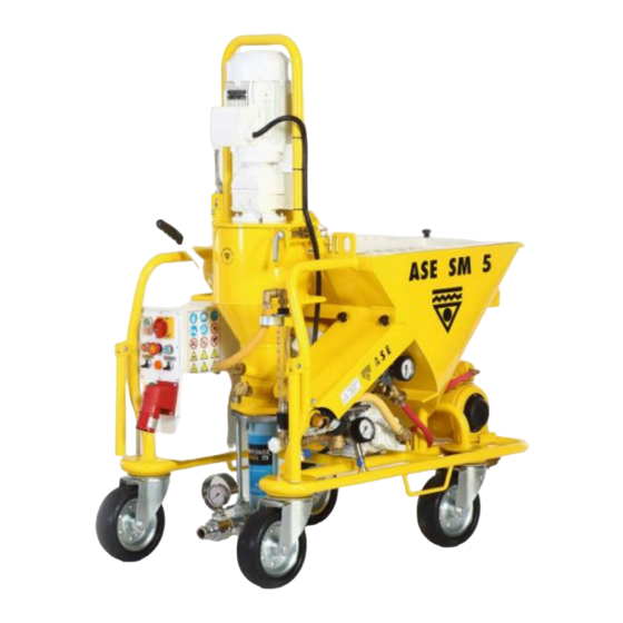
- Page 1 OPERATION MANUAL ASE SM 5 MIXING PUMP ASE MAKINE İNŞ. ELEKTRİK. SAN VE TİC A.Ş. ADDRESS : IVEDIK OSB MH. 1372 SK. NO:20, YENIMAHALLE, 06210 ANKARA - TURKEY : +90 312 256 56 33 FAX : +90 312 256 61 50 WEB: www.ase-co .com...
- Page 2 SM 5. If you need further information please do not hesitate to contact with our office. This manual supplied with the machine. Therefore, it may only be used for the purpose of operation of SM 5. It is forbidden to pass it on to third parties or to copy without permission.
- Page 3 1) OPERATING PRINCIPLE OF MACHINE: The dry premixed material in bags filled into the hopper by the motor driven star wheel. The material is fed into the mixing chamber through a trap door. A constant stream of water adjustable according to the requirements is injected into the mixing chamber where the mixing shaft driven by an electric geared motor mixes material and water homogeneously to a useable plaster.
-
Page 4: Operation Of Machine
2) OPERATION OF MACHINE: 1. Before running the machine, be sure about undistorted power supply and undistorted water supply (remember that it needs 380 V 50 Hz. 3-phase power supply to work and water supply with the pressure min. 3.5 bars). 2. - Page 5 with low pressure in the site. If the water line is proper then you can use the machine with ‘AUTO’ or ‘0’ position. Remember that you may read 3.5 bars in the water manometer when machine is not working, the supplying the water to machine may decrease this water pressure.
- Page 6 14. Correct plaster consistency is reached when the plaster flows smoothly on the surface sprayed. Insufficient water supply to the mixing unit will result in uneven mixing and spraying which again leads to considerable wear of both stator and rotor. 15.
- Page 7 3) DURING OPERATION PAY ATTENTION TO: 1- Don’t stop and add the material into the mixing chamber in the case that there exists material in the pump unit. 2- Every time after the change of mains plug, control the rotation direction of motor. Determine the warning indication lamp on the control cabinet.
-
Page 8: Cleaning The Machine
4) CLEANING THE MACHINE: 1- When spraying is finished, turn the star wheel commutator to position ‘0’. Then the pump should left to run until water comes out of the spraying gun. Then turn off the main switch. 2- Tilt and lift pump motor, take out mixing shaft and clean it thoroughly. 3- Insert cleaning shaft and cleaner into the pump unit and close the motor bracket. - Page 9 4) ADJUSMENT DATA: a) Water pressure safety switch: At minimum 2.2 bars machine starts to work. At the pressure lower than 2.0 bar machine stops itself automatically. b) Water pressure reduction valve: 1.7 Bar, 800 liter /hour c) Pneumatic remote control switch: 0.9 Bar: Machine Starts 1.2.
-
Page 10: Technical Data
6) TECHNICAL DATA: 1- Power: 2 transmission motors: Pump motor: 5.5 KW, 12.5 A, 380 V, 400 rpm Star wheel motor: 0.55 KW, 1.95 A, 380V, 28 rpm 2- Conveying pressure: 5-40 bar depending on type of plaster / rendering and pump used. - Page 11 7) TROUBLE AND SHOOTING: 1- Machine does not start although power and water are connected. Reasons: Insufficient water pressure. Manometer shows less than 2 bars. Remedies: Clean dirt collector and check air in the water pump. If so press the water button for a few seconds to remove the air.
- Page 12 7- Water level in pump rises in the mixing chamber during work. Reasons: Holding pressure in plaster hose is higher than pump pressure. Rotor or stator are worn out or damaged. Blockage in plaster hose is due to insufficient water supply.
- Page 13 Reason: Water pump and compressor of machine work at 220 V AC. So although the 380 V AC supply exist if there is no neutral line 220 V AC supply will not exist so water pump and compressor don’t work. Remedies: Control power supply lines and neutral line.
- Page 14 8) TROUBLES DUE TO MISUSAGE OF OPERATOR ARE NOT GUARANTEED: 1- In any way waters inside electricity panel. 2- Damaging and breaking in some parts of machine because of stroke 3- Damaging of some parts of machine (motor, compressor etc.) because of using power supply other than considered in instruction manual.
- Page 15 General view A: CONTROL PANEL D: DRY MATERIAL BUNKER B: MIXING–PUMPING CHAMBER E: COMPRESSOR C: WATER- AIR SYSTEM...
- Page 16 General view...
- Page 17 General view PART NAME PUMPING MOTOR MIXING CHAMBER AIR – WATER REGULATOR PUMP COMPRESSOR MALZEME KA DRY MATERIAL BUNKER PROTECTIVE GRID WITH BAG CUTTER STARWHEEL MOTOR CONTROL PANEL WATER PUMP...
- Page 18 Air – Water Regulator...
- Page 19 Air – Water Regulator Air to the spray gun Pressure reducer Solenoid valve Air from compressor Emptying tap Water regulating tap Water to the mixing chamber External water tap Flow meter Water from net or barrel Air-water block...
- Page 20 ÇALIŞTIRMA ve UYARI ELEMANLARI 1. Main torque switch 2. Star wheel(manual/automatic) manual-automatic Water pump 4. Green led Sign for mortar flow Red led / problem Panel socket R-Reverse Reverse pumping motor backward Water flow button Start Stop Cable socket Cable socket Cable socket Socket (220 V) Socket (Compressor)
- Page 21 Setting Data ( 1 ) Water pressure- safety circuit breaker Stop the machine at 1,9 bar. ( 2 ) Air pressure- safety circuit breaker Start the machine at 0,9 bar. Stop the machine at 1,2 bar. Stopping Compressor (1) Start the compressor at 2,0 bar (pressure difference/1,0 bar) (2) Stopping the compressor at 3,0 bar.
- Page 22 Setting Data ( 1 ) Pressure reducer regulator Maximum flow pressure 1,9 bar Motor safety circuit breaker (A / B type) ( 1 ) Pump motor 5,5 kw 400 V 11,5 A ( 2 ) Star wheel motor 0,55 kw 400 V 1,6 a...
- Page 23 Setting Data Pumping motor turning direction Check the motor propeller it supposed to turn counter clock wise direction. Star wheel motor turning direction operates independently of star Wheel turning direction. In case a SILOMAT-transportation vehicular is used, turning direction must be clock wise (default settings).
- Page 24 Control panel schema...
- Page 25 Power schema...
- Page 26 Spare part – Material hopper...
- Page 27 Spare part– Material hopper Part ID Part Name 99 08 1011 Star wheel dust cover Spring pin Ø 6 yellow galvanize 99 07 1910 99 07 1241 M 12 Fiber nut 99 08 1043 Fixing handle bed 99 08 1012 Fixing handle 99 07 7050 M 12 rondela...
- Page 28 Spare Part –Star Wheel group Spare Part – Star wheel Part ID Part Name 99 08 1018 Nut with ring 99 08 1017 Star wheel 99 08 1016 Motor coupling 99 03 3210 Motor 99 07 7050 Rondela M12 99 07 7040 M12 X 30 Screw hexagonal...
- Page 29 Spare Part- Mixing Chamber...
- Page 30 Spare Part- Mixing Chamber Part ID Part Name 99 03 3403 Pumping Motor (368 rpm) 99 08 1020 Overturning flange for motor 99 03 2010 Span handle 99 07 1250 M 8 Fiber nut 99 07 7010 M 8 Rondela 99 07 1076 M 8 X 35 hexagon socket 99 07 1070...
- Page 31 Spare Part- Pumping group...
- Page 32 Spare Part – Pumping group Part ID Part Name 99 07 1260 M 16 Nut 99 07 1550 M 16 Rondela 99 08 1025 Mixing chamber 99 07 7220 Gasket 120*3 99 08 1027 Upper flange 99 02 1000 Rotor D6-3 99 07 1810 Span sticks 99 02 2000...
- Page 33 Water-air block...
- Page 34 Water-air block 99 07 1020 M 8 X 20 Hexagonal screw 99 07 7010 M8 Rondela 99 07 1250 M8 Fiber nut ½” – 1 elongation 99 06 6205 99 03 7322 GKA 12 Coupling 99 03 7340 GKOR-N Gasket 99 06 6052 0-10 bar rear output manometer 99 07 1020...
- Page 35 Spare Part...
- Page 36 Spare Part Part ID Part Name ½” Pressure regulator part ½” Pressure regulator 99 06 6006 ½” Solenoid valve 24 vac 99 06 6030 ½”- 140 mm Pipe nipple 99 06 6213 ½” “T” 99 06 6140 ½” Mini round tap 99 06 6160 ½”...
- Page 37 Spare Part-Spraying gun Spare Part-Spraying gun Part ID Part Name 99 03 3643 (Ø14) Gun nipple 99 03 3645 (Ø18) 99 07 8007 M 6 Screw M8*30 99 03 3620 Spraying gun 25mm gon 99 03 3621 Spraying gun head 25mm platy 99 03 3622 Spraying gun head 35mm gon 99 03 3623...
- Page 38 Spraying gun ____________________________________________________________________________ Spraying gun Ø 25 Size:750 Spraying gun (Ø 14 Gun nipple ) Ø 25 Size:500 Spraying gun (Ø 14 Gun nipple) Ø 35 Size:500 Spraying gun (Ø 18 Gun nipple) Ø 35 Size:750 Spraying gun (Ø 18 Gun nipple) Ø...
Need help?
Do you have a question about the SM 5 and is the answer not in the manual?
Questions and answers