
Related Manuals for Krone KS2900


Summary of Contents for Krone KS2900
- Page 1 Operating Manual Differential Pressure Manometer MODEL KS2900 Krone Corporation HQ : post code 124-0023 9-6,Higashishinkoiwa 3 Chome, Katsushikaku Tokyo Japan TEL :+81-3-3695-5431 / FAX : +81-3-3695-5698 E-Mail : sales-tokyo@krone.co.jp...
- Page 2 1. Out Line The KS2900 is a very small sized digital difference pressure indicator which incorporates a mono- lithic silicon semiconductor pressure sensor. It is the best solution to very low pressure measurement. KS2900 is designed for the application of the semiconductor device equipment such as Coetar Developer, Cleaning and Furnace etc and has two transistor output(NPN or PNP(option)) and analog output 4-20mA or 1-5V (Optional). Connector type ( XH connector (JST) ) 2. Handling Note Recheck the following items before turning on the power. Input and output wires, If the output terminal is connected to the power the interior circuit will be damaged. Power voltage : Pressure range : Begin actual operation after the heat line is activated for over five minutes after the power is turned on. Excessive pressure. Please do not apply pressure exceeding the maximum pressure as shown in the specification on catalogues. The excessive pressure may affect the sensor characteristics and may make accurate measurement impossible. Insert and contact of foreign matter. A pressure sensor chip is placed inside the pressure port. If foreign matter such as wire inserts through the pressure port, damage could be occur. This must be absolutely avoided. • On this manual This Manual serves to illustrate the capabilities and appropriate use of the Pressure Controller KS2900. Inappropriate use or improper handling can lead to potential hazards for persons and intrinsic values. Therefore, any person entrusted with working with the device must be instructed and aware of the potential risks. This manual and its safety notices in particular must be addressed to with care. If any doubts occur concerning the proper understanding of any paragraph of this manual, please consult the manufacturing company. Handle this manual with care: • It has to be kept within reach as long as the device is on service. • It has to be handed over to successive personnel. • Any supplements edited by the manufacturer must be inserted in this manual. • If the equipment is used in a manner not specified by the manufacturer, the protection provided by the equipment may be impaired. • Do not close the pressure input ports when shipping, as changes in barometric pressure could damage instruments with low measuring ranges. • Only technical personnel who are appropriately trained and authorized by the operator of the facility may assemble the instrument and set up its electrical connections. • The instrument may only be operated by appropriately trained individuals who have been authorized by the operator of the facility. • Pressurized air or breath is not to be used for performance tests, as this could damage instruments with low measurement ranges.
- Page 3 3. Size 3-1 B8B-XH-A (8pins connector) Dimensions : mm Port guard Size for Panel cut Panel thickness 0.5 to 4mm Size for Front cover - 2 -...
-
Page 4: Specification
4. Specification Model KS2900 Method of pressure Differential Sensor Semi conductor piezoresistors wheatstone bridge Pressure range 0-100〜5000Pa、 ±100〜±5000Pa Display accuracy ±1%FS ±1digit, (More than 500Pa) 100Pa=±3%FS、 200Pa=±2%FS、 300Pa=±1.5%FS and ±1digit Temperature drift Max ±0.1%F.S./℃ (0〜50℃) Medium Air, non-corrosive dry gasses (dust is not permitted) Element Semi conductor silicon Over pressure / Burst pressure 0-100〜1000、 ±100〜±1000 : 5kPa/10kPa 0-2000〜5000、 ±2000〜±5000 : 7.5kPa/15kPa Power supply 12/24VDC(±10%) Power supply current 45mA (within 20mA-Aout,Backlight:on, without PNP output current) Setting method Digital setting by front panel Pressure setting range Hi and Lo 0-100%F.S (... -
Page 5: Pollution Degree
Item Specification Operating temperature range 0-50 ℃ (Not be freeze) Humidity Limits 35-85% Storage temperature range -20℃〜+70℃ Operating environment Indoor Altitude up to 2000 m POLLUTION DEGREE POLLUTION DEGREE 2 Protection standard IP40 Warming up time Not lower than 5 minute 0.1 sec Sampling rate Not lower than 100MΩ (Across the panel and terminals、 DC500V) Insulation resistance 500VAC (Across the panel and terminals、 50/60Hz 1 minute) withstand voltage max φ3.5mm (+) for high pressure, (-) for low pressure Pressure port (8pins ) JST : B8B-XH-A connector Electric connection ABS(Case) Material 24(H)x48(W)x66(D)mm : B8B-XH-A Dimensions Panel mount Mounting... -
Page 6: Terminal Description
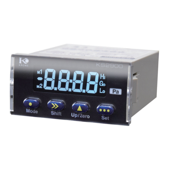
5.Terminal description 5-1 B8B-XH-A (8pins connector) 1 2 3 4 5 6 7 8 Port (+) JST Port (−) : B8B-XH-A (8pins) Pin number Terminal name Function contents Pin 1 Hi Alarm output NPN open corrector output PNP transistor output(option) Pin 2 Go (Good) Go signal output NPN open corrector output PNP transistor output(option) Pin 3 Lo Alarm output NPN open corrector output PNP transistor output(option) Pin 4 GND (COM) Power (common = GND) Pin 5 A COM ( - ) Analog output (common) Pin 6 A OUT ( + ) Analog output (out) GND (COM) Power (common = GND) - Page 7 7. Operaing components 7-1 Display [1] 7 segment LCD [2] Hi LCD [3] Go LCD [4] Lo LCD [5] MODE Key [8] SET Key [6] SHIFT Key [7] UP/Zero Key 7-2 Key functions (basic) Back to measurement mode Shift Change the value Return key + Jump to setting mode (M1,M2) (Over 5 sec.) → Zero adjustment 1min. 1min. Hi set Lo set Measure Display Display Display Hi Blink Lo Blink SET Key + SET Key SET Key During operation, display returns to measuring mode after 1 min. if no Key operation done. During Hi or Lo setting mode, measuring function is going on. - 6 -...
- Page 8 8. Setting menu Menu Display Description Indicates ” Alarm setting mode” To set alarm point for Hi 1_Hindicates Hi setting,1_Lindicates Low setting. Alarm condition of 1_Hor1_Lis to be selected in the Condition setting mode. Figure shifted by and set by key. Value can be set within range of −9999〜+9999digits. During setting operation, Hi LCD display lighting. To set alarm point for Lo 2_Hindicates Hi setting,2_Lindicates Low setting. Alarm condition of 2_Hor2_Lis to be selected in the Condition setting mode. Figure shifted by and set by key. Value can be set within range of −9999〜+9999digits. During setting operation, Lo LCD display lighting. Indicates ” Alarm condition setting mode” To set alarm condition for Hi. Set by key. 1_H :to set Hi alarm point. 1_L :to set Low alarm point. During setting operation, Hi LCD display lighting. To set hysteresis for Hi output to return from On to Off. Figure shifted by key and set by key. During setting operation Hi LCD display lighting. Mode change for Positive Logic or Negative Logic To set alarm condition for Lo. Set by key. 2_H :to set Hi alarm point. 2_L :to set Low alarm point. To set hysteresis for Lo output to return from On to Off. ...
- Page 9 9. Command Indicates ” Operation Condition setting mode” Manual ZERO setting ON / OFF mode( key) ZERO display under 5% FS (Adjustable) Sampling rate 0.1sec. Display rate selectable from 0.1/0.5/1/2/5/10 sec.( key) ZERO suppress ON / OFF Smallest digit ZERO ON / OFF ( key) Mode protection ON / OFF Active or non active for Analog output Analog output mode thr: output every 0.1 sec. diSP: Synchronize with Display + (and over 3sec.) + (and over 3sec.)→ → Backlight timer to auto off 0 sec. to 8888 sec.(8888 means ∞) Sampling average mode Display showing result of setting average. When performing serial communication using Press ON/OFF - 8 -...
-
Page 10: Parameter Table
10. Parameter table 10-1 Mode1 Parameter table Default Selectable + ( >3sec ) - 9 -... - Page 11 10-2 Mode2 Parameter table Default Selectable + ( >3sec ) - 10 -...
-
Page 12: Warranty
14. Warranty KRONE warrants the Products to be free of defects in materials and workmanship for a period of one year from the date of shipment. If any models or samples were shown to Buyer, such models or samples were used merely to illustrate the general type and quality of the Products and not to represent that the Products would necessarily conform to said models or samples. Any Products found to be defective must be shipped to KRONE with all shipping costs paid by Buyer or offered to KRONE for inspection and examination. Upon examination by KRONE, at its sole option, will refund the purchase price of, or repair or replace at no charge any Products found to be defective. This warranty does not apply to any defects resulting from any action of Buyer, including but not limited to improper installation, improper interfacing, improper repair, unauthorized modification, misapplication and mishandling, such as exposure to excessive current, heat, coldness, moisture, vibration or outdoors air. Components which wear are not warranted. Pressure port portion is thinner. Please be aware of the damage caused by overload. KRONE is pleased to offer suggestions on the use of its various Products. They are only suggestions, and it is Buyer's responsibility to ascertain the fitness of the Products for Buyerʼs intended use. KRONE will not be responsible for any damages that may result from the use of the Products. 40154-0017-12 - 11 -...
Need help?
Do you have a question about the KS2900 and is the answer not in the manual?
Questions and answers
How do you change the display from GO to HI?