Table of Contents
Advertisement
Quick Links
Installation and Operation Manual
Manual P/N 5900002 — Manual Revision D — August 2019
Models:
• PL-6SR
• PL-6SRX
Autostacker is designed and engineered by BendPak Inc. in Southern California, USA. Made in China.
⚠
DANGER
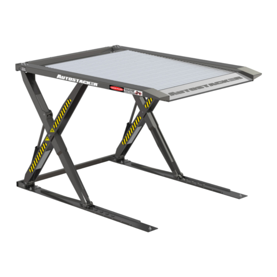
Autostacker™ Parking Lift
entire
Read the
to follow the instructions and safety precautions in this manual can result in
serious injury or death. Make sure all other operators also read this manual. Keep
the manual near the product for future reference. By proceeding with setup and
operation, you agree that you fully understand the contents of this manual.
contents of this Manual
1645 Lemonwood Dr.
Santa Paula, CA, 93060 USA
Toll Free (888) 977-8225
Tel: (805) 933-9970
autostacker.com
U.S. Design Patent No. D814,736
before
using this product. Failure
Advertisement
Table of Contents

Related Manuals for BendPak Autostacker PL-6SR

Summary of Contents for BendPak Autostacker PL-6SR
- Page 1 Manual P/N 5900002 — Manual Revision D — August 2019 Models: • PL-6SR • PL-6SRX U.S. Design Patent No. D814,736 Autostacker is designed and engineered by BendPak Inc. in Southern California, USA. Made in China. ⚠ entire before Read the contents of this Manual using this product.
- Page 2 Copyright. Copyright © 2019 by BendPak Inc. All rights reserved. You may make copies of this document if you agree that: you will give full attribution to BendPak Inc., you will not make changes to the content, you do not gain any rights to this content, and you will not use the copies for commercial purposes.
-
Page 3: Table Of Contents
Table of Contents Introduction Installation Shipping Information Operation Safety Considerations Maintenance Troubleshooting Specifications Multi-Autostacker Components Wiring Diagrams Will My Cars Fit? Labels Orientation Parts Diagrams Installation Checklist Introduction This manual describes both Autostacker versions, which can easily and quickly raise a Vehicle so that you can park a second Vehicle underneath. -
Page 4: Shipping Information
⚠ DANGER Be very careful when setting up, operating, maintaining, or repairing this equipment; failure to do so could result in property damage, product damage, injury, or (in very rare cases) death. Make sure only authorized personnel operate this equipment. All repairs must be performed by an authorized technician. - Page 5 BendPak Inc. assumes no liability for damages resulting from: • Use of the product for purposes other than those described in this manual. • Modifications to the equipment without prior, written permission from BendPak Inc. • Damage to the equipment from external influences. •...
-
Page 6: Faq
A: Yes, but the Lift is designed for indoor installation, so there are some additional things you will need to do; cover the Console, put a canopy over the Lift, keep it clean and dry, and increase maintenance. Contact BendPak Customer Service (via the web bendpak.com/support, via email techsupport@bendpak.com, or via phone (800) 253-2363 for additional information. -
Page 7: Specifications
Specifications Specifications PL-6SR PL-6SRX Lifting capacity 6,000 lbs. / 2,722 kg A Total width 103" (8.6 feet) / 2,620 mm 111" (9.3 feet) / 2.815 mm B Platform width 83.75" (7 feet) / 2,127 mm 91.75" (7.7 feet) / 2,331 mm C Drive-thru width 83"... -
Page 8: Components
Components Autostacker components include: • Console. Hosts the Controls for your Autostacker and the Power Unit. The Console is designed to go on either side of the front of the Autostacker. The included Hydraulic Hoses let you put the Console up to 30 inches away from the Autostacker. For a Single-Lift setup. •... - Page 9 The following drawing shows the two possible locations for the Lift Controls: The Console for a Single-Lift configuration versus the Control Stand for a Multi-Lift configuration. Console: Control Stand: Autostacker™ Parking Lift P/N 5900002 — Rev. D — August 2019...
-
Page 10: Will My Cars Fit
Will My Cars Fit? The Autostacker accommodates a wide variety of cars, light trucks, and SUVs. This section describes how to get wider, longer, and taller Vehicles onto your Autostacker. Width Considerations for Vehicle width include: • Platform width. The width from the outside of the left tires to the outside of the right tires cannot must exceed the width of the Platform. -
Page 11: Orientation
Orientation The following diagram shows the Console on the right side; it can be placed on either side up to 30 inches away from the Lift. Not all components are shown. Drawing not necessarily to scale. Autostacker™ Parking Lift P/N 5900002 — Rev. D — August 2019... -
Page 12: Installation Checklist
Installation Checklist Following are the steps needed to install an Autostacker; perform them in this order. ☐ 1. Review the installation Safety Rules. ☐ 2. Make sure you have the necessary Tools. ☐ 3. Plan for Electrical Work. ☐ 4. Select the installation site. ☐... -
Page 13: Installation
Use appropriate tools and lifting equipment, when needed. Stay clear of moving parts. BendPak recommends referring to the current version of the ANSI/ALI ALIS Standard Safety Requirements for Installation and Service for more information about safely installing, using, and servicing your Lift. - Page 14 Thermal • Install a Disconnect Switch. Optional. BendPak recommends connecting a Thermal Disconnect Switch or overload device (not supplied) to make sure the equipment shuts down in the event of an overload or an overheated motor. Refer to Install a Thermal Disconnect Switch for more information.
- Page 15 • Dress properly. Wear protective gear (like safety goggles, helmet, heavy gloves, suitable working clothes, safety boots, ear protection, and so on) when installing Autostacker. Do not wear loose clothing or jewelry; contain long hair; keep hair and clothing away from moving parts. ⚠...
- Page 16 • Console. The Console must be located near the Autostacker; the Hydraulic Hoses that come with the Autostacker are optimized for up to 30 inches between the Autostacker and the Console. If you want the Console further than 30 inches from the Autostacker, you can use must custom Hydraulic Hoses.
- Page 17 Create Chalk Lines Guides Using Chalk Line Guides makes it easy to position the Autostacker components for installation. opposite Note: The front of the Autostacker is the end the Drive-Up Ramp. The Tire Trough is at the front of the Autostacker and the Drive-Up Ramp is at the back. Autostacker™...
- Page 18 To add Chalk Line Guides : 1. Decide where you want to place the Autostacker. 2. Create an Alignment Chalk Line where you want the front of the Autostacker. longer Make the Alignment Chalk Line than the Total Width setting for the Autostacker. 3.
- Page 19 Position the Autostacker Components When the Lift components are delivered to the site, try to have them placed near where you will be installing the unit. For example, if you are installing Autostacker in a garage, you might want to have the components unloaded on the garage’s driveway or inside the garage.
- Page 20 Attach the Bottom and Top Connector Tubes The Bottom Connector Tube holds the bottom of the Autostacker structure together. It is hollow, allowing the Hydraulic Hoses and the Return Line to be routed through it. Each end of the Bottom Connector Tube connects to the corresponding end of a Leg Assembly base. The Top Connector Tube holds the top of the Autostacker structure together.
- Page 21 Anchor Bases to the Ground Both Autostacker Bases have three holes in them for anchoring the base to the ground, with two holes placed in the front of each Leg Assembly and one located in the back. If you prefer, you can defer anchoring the Autostacker Bases into place until later in the installation.
- Page 22 To check your Autostacker alignment prior to anchoring: 1. Using the drawing as a guide, measure A and B to make sure your Leg Assemblies are parallel. If the values are different, adjust as necessary. 2. Measure 1 and 2 to check your diagonal measurements. If the values are different, adjust as necessary.
- Page 23 To anchor your Autostacker to the ground: 1. Double check to make sure the Autostacker Bases are where you want them. Once Anchor Bolts are torqued into position, they are not easily removed. Make sure the Leg Assemblies are correct before anchoring. 2.
- Page 24 The holding strength of an Anchor Bolt is partly based on how cleanly the Expansion Important: Sleeve presses against the Concrete. If the hole is dirty, the Expansion Sleeve does not press as cleanly. If the hole is too wide, the Expansion Sleeve does not press with as much force.
- Page 25 Assemble the Console and Attach the Power Unit The Console can go on either side of the front of the Autostacker. The Console only works with Single- Lift configurations. The Console comes unassembled from the factory. This section describes how to assemble Note: the Console and attach the Power Unit inside the Console.
- Page 26 The following procedure includes instructions for anchoring the Console into place. If you prefer, you can defer anchoring the Console into place for later. Simply return to this section when you want to anchor the Console into place. To assemble the Console and attach the Power Unit: 1.
- Page 27 Connect the Hydraulic Hoses Hydraulic Hoses provide hydraulic power to the Hydraulic Cylinders, which is used to raise and lower the lift. If you have a Multi-Lift setup, this procedure will be different for you ; see Multi- towards the end of this manual for modified instructions. Autostacker The Autostacker comes with two Hydraulic Hoses, of different lengths: •...
- Page 28 To connect the Hydraulic Hoses: 1. Locate the two Hydraulic Hoses that come with your Lift. 2. Starting near the Console, route the Long Hydraulic Hose through the Bottom Connector Tube and pull it out at the Hydraulic Cylinder that is furthest away from the Console. Leave enough Hose on the Console end to allow the Long Hydraulic Hose to be connected to the Power Unit up through one of the openings at the bottom of the Console.
- Page 29 Connect the Return Lines The Return Lines take extra Hydraulic Fluid from the Hydraulic Cylinders and returns it to the Power Unit’s Hydraulic Fluid Reservoir; it also allows air to move in and out of the Hydraulic Cylinders. One end of the Return Line connects to the Power Unit (where it goes into the Reservoir). There are two other ends;...
- Page 30 Working with Return Lines and Compression Fittings Autostacker uses Return Lines made of a roll of ¼ inch, polyethylene Tubing (also called Poly-Flo®) that is used with Compression Fittings to attach to the Air Cylinders and the Return Line Connectors. The components involved with Compression Fittings include: •...
- Page 31 Connect the Power Unit The Power Unit comes assembled from the factory. You need to attach it to the back of the Console and then connect it properly, described in this section. If you have a Multi-Lift setup, this procedure will be different for you ;...
- Page 32 Depending on your Power Unit, the connector locations may be different. Use the drawing below to identify your layout and then attach your Hydraulic Hoses and Return Line appropriately. ⚠ CAUTION The Hydraulic Power Ports are almost always labeled P1/P2; the Hydraulic Return Ports are commonly labeled T1/T2 or CV1/CV2.
- Page 33 To make connections to the Power Unit and add Hydraulic Fluid: 1. Remove the Top and Front of the Console if they are currently in place. 2. Locate the Female (Molex™) Connector on the Power Unit and attach it to the Male Connector that comes from the Controls in the Top of the Console.
- Page 34 Wiring a Power Disconnect Switch ⚠ must DANGER All wiring be performed by a licensed, certified Electrician. Do not perform maintenance or installation on the Lift without first making sure that main cannot electrical power has been disconnected from the lift and be re-energized until all procedures are complete.
- Page 35 ⚠ DANGER Do not perform the following procedure until you are certain the Power Unit is disconnected from power and cannot be re-energized. All electrical work must be performed by a licensed, certified Electrician. If your organization has Lockout/Tagout policies, make sure to implement them after connecting to a power source.
- Page 36 Test the Autostacker Before putting your Autostacker into normal operation, we recommend breaking it in by raising and lowering it a few times. This will help you get a feel for how to operate it and also helps to get any residual air out of the hydraulic system.
- Page 37 Add the Tire Trough and Tire Stops The Tire Trough is a lowered section of the Platform that holds the tires of the Vehicle. The Tire Stops attach to the top of the Tire Trough and add a bit of extra height for holding Vehicles with larger tires. The Tire Trough functions as a tire chock;...
- Page 38 Add the Platform Sections and the Drive-Up Ramp The Platform sections, when installed, create the Platform. The Drive-Up Ramp lets you drive a vehicle onto the Platform. The Platform sections are most easily installed from underneath. Raise the Autostacker to a height that is good for you. ⚠...
- Page 39 Lubricate the Lift The Autostacker has eight Lubrication Points, four on each Leg Assembly. You must grease the Threaded Grease Fitting at the Lubrication Points before you start normal operation of your Autostacker. Refer to for more information about how often to Maintenance grease the Lubrication Points after the start of normal operation.
- Page 40 Final Checklist Make sure these things have been done before using your lift: • Review the Installation Checklist to make sure all steps have been performed. • Make sure the Power Unit is getting power from the power source. • Check the Power Unit’s Hydraulic Fluid reservoir;...
-
Page 41: Operation
Operation This section describes how to operate your Autostacker. ⚠ WARNING Always use care when you are around the Autostacker. When it is lowered, be careful not to trip over it. When it is raised, be careful not to bang your head on the When the Autostacker is moving, keep all Drive-Up Ramp or Platform. - Page 42 Raising a Vehicle This section describes how to position a Vehicle on the Autostacker and raise it. To raise a Vehicle: 1. Make sure the Platform is fully lowered, then drive the Vehicle onto the Platform, either nose first or backed in.
- Page 43 About Safety Locks Each Leg Base has six Safety Locks; they serve two important functions: • Safety. Safety locks hold the Platform in place. Once your Autostacker is on the Safety Lock Blocks, the weight of the Vehicle pressing down holds the Platform in place without requiring any energy.
- Page 44 3. To use that Safety Lock, keep pressing Up for another half a second, then release Up. 4. Press Down for a few seconds; the Lock Hood moves into a locked position on the Lock Block it just passed. The Lock Hood is securely on the Lock Block.
- Page 45 Lowering a Vehicle This section describes how to get a Vehicle off of the Autostacker Platform. To lower a Vehicle: 1. Check the items listed in Preparing to Raise or Lower a Vehicle. If you find any issues, resolve them before lowering the Vehicle. 2.
- Page 46 About Velocity Fuses Velocity Fuses are a safety feature. They stop hydraulic flow in the event of a Hydraulic Hose failure. Every Autostacker comes with one Velocity Fuse per Hydraulic Cylinder. The way a Velocity Fuse works is this: When the Platform is being raised, Hydraulic Fluid moves from the Power Unit to the Hydraulic Cylinder, which uses this force to raise the Platform.
-
Page 47: Maintenance
Maintenance ⚠ Before performing any maintenance on your Autostacker, make sure it is DANGER: completely disconnected from power . If your organization uses Lockout/Tagout policies, make sure to implement them after connecting to a power source. To maintain your Autostacker: •... -
Page 48: Troubleshooting
Troubleshooting This section describes how to troubleshoot your Lift. If your Lift is not functioning correctly, you must take it out of service until it is fixed. Note: must Important: All repair work be done by qualified personnel. Issue Action to Take Platform moves erratically Move the Platform up and down a few times, with a break between or squeaks when in use. - Page 49 Optional Access Panel The optional Autostacker Access Panel gives you access to the underside of the Vehicle that is raised on an Autostacker, making it into a Service Lift in addition to a Parking Lift. standard PL-6SR You can install up to two Access Panels per Autostacker, which works with the model only An Access Panel is made up of two pieces: •...
- Page 50 To install an Access Panel: 1. If you have already installed the Platform sections, remove them. 2. Put the Access Panel in the general location where you want it. 3. Starting next to the Tire Trough, put a Platform section next to the Tire Trough and then slide the end closest to the Tire Trough under it slightly.
-
Page 51: Multi-Autostacker
Multi-Autostacker Autostacker is available in a Multi-Lift configuration where you can control up to 12 Lifts with one Master Power Unit; however, only Lift can be raised or lowered at a time. The installation for each Autostacker in a Multi-Lift setup is similar to that of a single Autostacker. The main differences include separate procedures for routing the Hydraulic Hoses and the Return Line to a Master Power Unit, in addition to installing a Control Stand for each Lift that allows you to operate a specific Autostacker in your setup. - Page 52 Specifications Front Control Stand – of the PL-6SR PL-6SRX Lift A Total width 111" (9.3 feet) / 2,815 mm 103" (8.6 feet) / 2,616 mm B Platform width 83.75" (7 feet) / 2,127 mm 91.75" (7.7 feet) / 2,331 mm C Drive-thru width 83"...
- Page 53 Positioning the Bottom Connector Tube If you want to position the Control Stand at the Rear end of Lift (the Drive-up end), make sure the Window for routing the Control Stand wires through the Bottom Connector Tube is on the same side of the Lift where the Control Stand will go.
- Page 54 Installing the Hydraulic Hoses In a Multi-Lift configuration, Hydraulic Fluid moves from the Reservoir, goes past a number of Lifts, then reaches the two Hydraulic Cylinders of the Lift you want to use. To install the Hydraulic Hoses, you will use parts from two separate kits: The MPU Plumbing Kit and the Control Kit. To connect the Power Unit to the first Lift, you will need from the MPU Plumbing Kit: •...
- Page 55 each In addition, for Lift in your setup, you need from the Control Kit: • Two Short Hydraulic Hoses (15 inches). One end connects to a Hydraulic Cylinder and the other end connects to the Solenoid Valve Block. One per Hydraulic Cylinder. •...
- Page 56 8. Attach a Short Hydraulic Hose to each Hydraulic Line Assembly, then attach the other end of each Hose to the Elbow Fitting on the Solenoid Valve Blocks. The Solenoid Valve Blocks are labeled S1 through S4; they are only labeled here to distinguish between the various components.
- Page 57 The following drawing shows the connections to make to the last Tee Fittings. Not drawn to scale. Some components are exaggerated or not shown for easier understanding. 20. If there are additional Lifts to connect the Hydraulic Hoses to, continue repeating steps 1 through18 until you reach your ideal configuration, then complete step 19.
- Page 58 Installing the Return Line As previously mentioned, the Return Line takes extra Hydraulic Fluid from the Hydraulic Cylinders and returns it to the Power Unit’s Reservoir; refer to Connect the Return Lines for more information. The following drawing shows how to connect the Return Lines between two Autostackers. Not to scale.
- Page 59 Attach the Conduit Tube In order to place the Control Stand at the Rear of the Lift, you need to first attach the Conduit Tube to the Bottom Connector Tube. If you plan to position the Control Stand at the Front of the Lift, continue to the next section. As mentioned in Tube, there is a Window on the Bottom Positioning the Bottom Connector...
- Page 60 Installing the Control Stands The Control Stand holds the Controls to operate a Lift in your setup; each Lift has its own Control Stand. The Control Stand can be placed at the Front or Rear of the Lift, although the installation for either orientation is different.
- Page 61 7. Connect the remaining 16-6 wires to the 14-4 wires coming out of the Bottom Connector Tube. Refer to Wiring Diagrams for wiring information. 8. Attach the Control Box to the Stand using a Bolt, Washer, and Nut in each hole, placing the Safety Placard Bracket between the Control Stand Plate and a Washer.
- Page 62 Rear The following drawing shows the Control Stands at the of the Lift. Rear To install the Control Stand at the of the Lift: 1. Find the 14-4 Cable and route it through the Bottom Connector Tube to the Conduit Fitting. 2.
- Page 63 10. Move the Control Stand out of the way, then drill two holes 3/8" wide by 4" (102 mm) deep in the concrete floor at the locations you marked. Go in straight; do not let the drill wobble. Use a carbide bit (conforming to the current ANSI B212.15).
- Page 64 Contacting the Electrician As mentioned previously, there are installation tasks that require a licensed, certified Electrician. ⚠ must DANGER All wiring be performed by a licensed, certified Electrician. If someone who is not a certified Electrician attempts these tasks, they could damage the Lift or be electrocuted, resulting in serious injury or even death.
- Page 65 The Power Unit for your Lift setup is either 220 VAC, 60Hz, 1Ph or 208-230/460 VAC, 50/60 Hz, 3 Ph. The Power Unit must be connected to an appropriate power source. BendPak offers an optional MPU Enclosure that protects the Power Unit from the outdoor elements. Call (800) 253-2363 for more information.
- Page 66 ⚠ must DANGER All wiring be performed only by a licensed, certified Electrician. Do not perform any maintenance or installation on the Lift without first making sure that main electrical power has been disconnected from the Lift and cannot be re- energized until all procedures are complete.
- Page 67 Operation Before operating an Autostacker in your Multi-Autostacker lineup, make sure to check the Lift and the surrounding area for safety. Refer to Preparing to Raise or Lower a Vehicle for a safety checklist and operation instructions. The Controls Your Autostacker is operated via the Controls; the Controls used in your Multi-Lift setup are similar to the Controls used with a standard Autostacker.
-
Page 68: Wiring Diagrams
Wiring Diagrams Autostacker™ Parking Lift P/N 5900002 — Rev. D — August 2019... - Page 69 Autostacker™ Parking Lift P/N 5900002 — Rev. D — August 2019...
- Page 70 Autostacker™ Parking Lift P/N 5900002 — Rev. D — August 2019...
- Page 71 Multi-Autostacker Each Control Stand requires three Electrical Cables, of varying gauges: • #14 AWG. Four wires; Green, Red, Black, and White. One end of the Cable goes to the Power Unit, and the other end goes through the Bottom Connector Tube, connecting to each Lift. •...
- Page 72 Autostacker™ Parking Lift P/N 5900002 — Rev. D — August 2019...
- Page 73 Autostacker™ Parking Lift P/N 5900002 — Rev. D — August 2019...
-
Page 74: Labels
Labels Autostacker™ Parking Lift P/N 5900002 — Rev. D — August 2019... - Page 75 Autostacker™ Parking Lift P/N 5900002 — Rev. D — August 2019...
- Page 76 Autostacker™ Parking Lift P/N 5900002 — Rev. D — August 2019...
- Page 77 Autostacker™ Parking Lift P/N 5900002 — Rev. D — August 2019...
- Page 78 Autostacker™ Parking Lift P/N 5900002 — Rev. D — August 2019...
- Page 79 Autostacker™ Parking Lift P/N 5900002 — Rev. D — August 2019...
-
Page 80: Parts Diagrams
Parts Diagrams Autostacker™ Parking Lift P/N 5900002 — Rev. D — August 2019... -
Page 81: P/N 5900002 — Rev. D — August
Autostacker™ Parking Lift P/N 5900002 — Rev. D — August 2019... - Page 82 Autostacker™ Parking Lift P/N 5900002 — Rev. D — August 2019...
- Page 83 Autostacker™ Parking Lift P/N 5900002 — Rev. D — August 2019...
- Page 84 Autostacker™ Parking Lift P/N 5900002 — Rev. D — August 2019...
- Page 85 Autostacker™ Parking Lift P/N 5900002 — Rev. D — August 2019...
- Page 86 Autostacker™ Parking Lift P/N 5900002 — Rev. D — August 2019...
- Page 87 Autostacker™ Parking Lift P/N 5900002 — Rev. D — August 2019...
- Page 88 Autostacker™ Parking Lift P/N 5900002 — Rev. D — August 2019...
- Page 89 Autostacker™ Parking Lift P/N 5900002 — Rev. D — August 2019...
- Page 90 Autostacker™ Parking Lift P/N 5900002 — Rev. D — August 2019...
- Page 91 Autostacker™ Parking Lift P/N 5900002 — Rev. D — August 2019...
- Page 92 Autostacker™ Parking Lift P/N 5900002 — Rev. D — August 2019...
- Page 93 Autostacker™ Parking Lift P/N 5900002 — Rev. D — August 2019...
- Page 94 Autostacker™ Parking Lift P/N 5900002 — Rev. D — August 2019...
- Page 95 Autostacker™ Parking Lift P/N 5900002 — Rev. D — August 2019...
- Page 96 Autostacker™ Parking Lift P/N 5900002 — Rev. D — August 2019...
- Page 97 Autostacker™ Parking Lift P/N 5900002 — Rev. D — August 2019...
- Page 98 Autostacker™ Parking Lift P/N 5900002 — Rev. D — August 2019...
- Page 99 Autostacker™ Parking Lift P/N 5900002 — Rev. D — August 2019...
- Page 100 Autostacker™ Parking Lift P/N 5900002 — Rev. D — August 2019...
- Page 101 Autostacker™ Parking Lift P/N 5900002 — Rev. D — August 2019...
- Page 102 Autostacker™ Parking Lift P/N 5900002 — Rev. D — August 2019...
- Page 103 Autostacker™ Parking Lift P/N 5900002 — Rev. D — August 2019...
- Page 104 1645 Lemonwood Drive Santa Paula, CA 93060 USA © 2018 BendPak Inc. All rights reserved. bendpak.com...
Need help?
Do you have a question about the Autostacker PL-6SR and is the answer not in the manual?
Questions and answers