Table of Contents
Advertisement
Quick Links
- 1 Installation Instructions
- 2 Wiring Requirements
- 3 Thermostat, Optional Indoor Temperature Sensor & Thermostat Communication Cable Installation
- 4 CCC 2 System Low Voltage Wire Connections
- 5 Simple Rv Wiring Diagram
- 6 Electronic Control Kit Wiring Diagrams
- 7 Unit Wiring Diagrams
- Download this manual
REVISION A
Form No. 3316207.000 09/16
(French 3316208.000_A)
©2016 Dometic Corporation
LaGrange, IN 46761
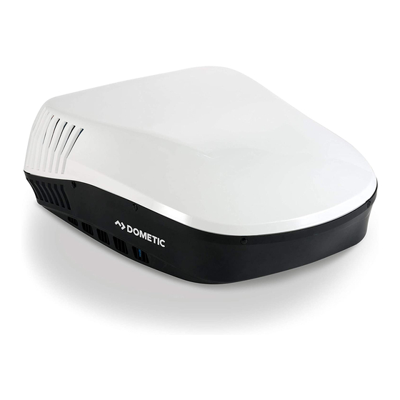
Roof Top Unit Used With 3105007.XXX OR 3105935.XXX Return Air Grille
Description
Blizzard NXT
TM
Model
Air Conditioner
CCC 2 Controls
H540315
H540316
LCD SZ Controls
H540315
H540316
This Unit is designed for OEM installation. All initial installations must be approved by Dometic Corporation.
Read these instructions carefully. These
instructions MUST stay with this product.
USA
SERVICE OFFICE
Dometic Corporation
1120 North Main Street
Elkhart, IN 46514
RECORD THIS INFORMATION FOR FUTURE
REFERENCE:
Model Number
Serial Number
Date Purchased
Electronic Control Kit
Thermostat
3312020.000
3314082.000 CCC 2-Blk
3314082.011 CCC 2-Wht
3313189.000 C/F-Wht
3313192.000 C/F-Wht
3313189.015 C/F-Blk
3313192.019 C/F-Blk
CANADA
Dometic Corporation
46 Zatonski, Unit 3
Brantford, ON N3T 5L8
CANADA
Optional Indoor
Temperature
Sensor
3311931.000-20'
3311931.012-40'
3311931.020-60'
N/A
SERVICE CENTER &
DEALER LOCATIONS
Please Visit:
www.eDometic.com
Advertisement
Table of Contents

Related Manuals for Dometic Blizzard NXT H540315


Summary of Contents for Dometic Blizzard NXT H540315
- Page 1 3313189.000 C/F-Wht 3313192.000 C/F-Wht H540316 3313189.015 C/F-Blk 3313192.019 C/F-Blk This Unit is designed for OEM installation. All initial installations must be approved by Dometic Corporation. Read these instructions carefully. These instructions MUST stay with this product. CANADA SERVICE CENTER &...
-
Page 2: Table Of Contents
Recreational Vehicle (hereinafter referred to as RV) during the time it is manufactured. This unit can be installed by one person with brief help from additional personnel. Use these instructions to ensure a properly installed, and properly functioning product. Dometic Corporation reserves the right to modify appearances and specifications without notice. TABLE OF CONTENTS INTRODUCTION ..................................2 DOCUMENT SYMBOLS ................................2... -
Page 3: Important Safety Instructions
R ead and follow all safety information and product except those specifically authorized in instructions to avoid possible injury or death. writing by Dometic Corporation. Read and understand these instructions be- fore [installing / using / servicing / performing maintenance on] this product. -
Page 4: Specifications
For wire length over 24 ft., consult the National Electrical Code for proper sizing. ** Dometic Corporation gives GENERAL guidelines for generator requirements. These guidelines come from experiences people have had in actual applications. When sizing the generator, the total power usage of your RV must be considered. -
Page 5: Installation Instructions
INSTALLATION INSTRUCTIONS Choosing Proper Location For Unit The roof must be designed to support 130 pounds when RV is in motion. Normally a This unit is specifically designed for installation on the roof 200 lb. static load design will meet this re- of an RV. When determining your cooling requirements, the quirement. -
Page 6: Air Distribution Duct Sizing & Design
3/4″ Min. Won't Collapse When 6. Air Distribution System Installation Bolting Down Unit a. Dometic Corporation recommends the basic configuration shown in (FIG. 5), for installing this system. We have found by testing, that this configuration works best in most applica- tions. It is the responsibility of the installer to review each RV floor plan to determine the 15″... -
Page 7: Wiring Requirements
INSTALLATION INSTRUCTIONS Duct Size And Requirements For 3105007.XXX And 3105935.XXX RAG FIG. 5 Register Required Registers 8 Min - 12 Max. (Per Unit) 14 Sq. In. Free Area Per Register Wiring Requirements 3. Thermostat Communication Cable a. CCC 2 Thermostat 1. -
Page 8: Choosing Thermostat Location
INSTALLATION INSTRUCTIONS Thermostat, Optional Indoor 4. (CCC 2 system only) Optional Indoor Tempera- ture Sensor Temperature Sensor & Thermostat a. Route an indoor temperature sensor (option- Communication Cable Installation al) from the roof opening to the indoor tem- 1. CCC 2 System perature sensor location. -
Page 9: Placing Unit On Roof
INSTALLATION INSTRUCTIONS b. Route the communication cable through the 2. LCD SZ System 2" diameter hole in the wall required for the W ire colors listed for the communication thermostat. See (FIG. 8). cable (3 conductor cable) match the wire c. -
Page 10: Installing Unit
INSTALLATION INSTRUCTIONS and could cause a leak. FIG. 14 Lift and place the unit over the prepared open- Divider Plate ing using the gasket on the unit as a guide. See Ceiling (FIG. 12). Template FIG. 12 Return Air Lift And Place Cover Front Return Air... - Page 11 INSTALLATION INSTRUCTIONS Place the divider plate up to bottom of the FIG. 16 Front Of Vehicle unit base pan firmly. The foam tape on the di- Roof vider plate must seal to bottom of base pan. Gasket Screws See (FIG. 18). FIG. 18 Tighten To Compress Gasket To 3/4″ Push Divider Plate Firmly Onto Base Pan 6.
-
Page 12: Lcd Sz System Low Voltage Wire Connections
INSTALLATION INSTRUCTIONS LCD SZ System Low Voltage Wire g. Plug the 6 pin electrical cord from the unit into the matching 6 pin connector in the elec- Connections tronic control box. The plug is polarized and Reach up into the return air opening and pull down the will only fit in one direction. -
Page 13: 120 Vac Power Supply Connection
INSTALLATION INSTRUCTIONS 5. Plug the indoor temperature sensor cable (if ap- FIG. 22 plicable) into the P4 (white) 2 pin matching con- nector in the electronic control box. 6. Connect the previously run Energy Manage- ment System wires (if applicable) to the yellow wires in the 6 wire harness. -
Page 14: Installing Return Air Cover
INSTALLATION INSTRUCTONS h. Gen Start selection - Leave in the "OFF" po- a. Re-connect the 12 Vdc and 120 Vac power sition. supplies. i. Install electronic control box cover. b. Make sure the CCC 2 thermostat is in the OFF mode. j. -
Page 15: General Information
For a more permanent solution to high heat gain, acces- sories like Dometic outdoor patio and window awnings will reduce heat gain by removing the direct sun. They also add a nice area to enjoy company during the cool of the evening. -
Page 16: Wiring Diagrams
WIRING DIAGRAMS Simple RV Wiring Diagram FIG. 27 (OPTIONAL) -
Page 17: Unit Wiring Diagrams
WIRING DIAGRAMS Unit Wiring Diagrams 2. 3313189.000 & 3313189.015 LCD SZ Electron- ic Control Kit Wiring Diagram Cool/Furnace 1. H540315 & H540316 Wiring Diagram FIG. 30 FIG. 28 Electronic Control Kit Wiring Diagrams 1. 3312020.000 CCC 2 Electronic Control Kit Wiring Diagram FIG.
Need help?
Do you have a question about the Blizzard NXT H540315 and is the answer not in the manual?
Questions and answers