Table of Contents
Advertisement
Advertisement
Table of Contents

Subscribe to Our Youtube Channel
Related Manuals for Shrinkfast 998 UL


Summary of Contents for Shrinkfast 998 UL
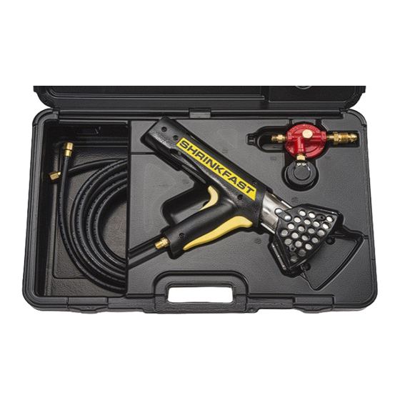
- Page 1 ® Operating, Field Maintenance, and Parts Manual Model 998 UL...
-
Page 2: Table Of Contents
TABLE OF CONTENTS GENERAL SAFETY PRECAUTIONS................pages 2-4 REGULATOR OPERATION & MAINTANANCE............pages 5-7 STARTING THE HEAT TOOL ....................page 8 REGULATOR MAINTANANCE & SAFETY FEATURES ........... pages 9-10 EXCESS FLOW DEVICE ...................... page 9 CHOOSING THE CORRECT PROPANE TANK ............pages 11-12 TANK PRESSURE, TEMPERATURE &... - Page 3 G G E E N N E E R R A A L L S S A A F F E E T T Y Y P P R R E E C C A A U U T T I I O O N N S S - - R R E E A A D D A A L L L L I I N N S S T T R R U U C C T T I I O O N N S S B B E E F F O O R R E E O O P P E E R R A A T T I I N N G G T T H H I I S S H H E E A A T T T T O O O O L L •...
-
Page 4: General Safety Precautions
GENERAL SAFETY PRECAUTIONS When working with any type of heat or open flame, always keep a fire • extinguisher close by. Always were safety glasses and gloves (flame retardant or leather is suggested) • when shrink wrapping. Never obstruct or cover the air inlet at the back of the heat tool. - Page 5 Once heat is applied to the shrink film, it will continue to shrink even after the heat is moved away from the area. Never modify the tool in any way and use only Shrinkfast replacement parts. • Never operate in a basement or closed in, non-ventilated area.
-
Page 6: Regulator Operation & Maintanance
REGULATOR OPERATION & MAINTANENCE Adjustable Hand Wheel 0 – 30 PSI Pressure Gauge – Adjusts PSI Setting of the Regulator POL – Attaches to Hose Adapter – the Propane Tank Attaches to the Supplied 25’ Hose Regulator Technical Overview: The MEGR-6120 is a high capacity, pounds to pounds, industrial gas regulator. •... - Page 7 This is a variable regulator assembly and the heat tool will operate properly between 15 PSI and 30 PSI. The pressure can be changed by loosening the hex nut located under the black, round hand wheel on the regulator assembly and then turning the hand wheel to the desired pressure. However, the optimum and factory recommendation is that you do not adjust the pressure and keep the regulator set at the factory setting of 22 PSI.
- Page 8 2. Connect one end of the supplied 25’ hose to the hose adapter on the regulator and the other end of the hose to the heat tool. Tighten all fittings with the supplied wrench (left handed threads, so tighten counter clockwise). 3.
-
Page 9: Starting The Heat Tool
STARTING THE HEAT TOOL 1. Depress the yellow safety that sits in the palm of your hand. If you do not depress the safety first, you will not be able to pull the trigger with your finger tips and ignite the heat tool. 2. -
Page 10: Regulator Maintanance & Safety Features
Regulator parts showing wear should be replaced as necessary. Contact your local distributor or Shrinkfast directly for descriptions and part numbers. IMPORTANT SAFETY FEATURE: Inside the POL fitting on the Regulator Assembly there is a safety featured called the “Excess Flow Device”. - Page 11 • Once the fuel has filled the entire hose and the regulator gauge reaches 22 PSI, the Excess Flow Device reopens and the heat tool is ready for operation (you will hear an audible “click” from the POL when the pressurization is complete).
-
Page 12: Choosing The Correct Propane Tank
CHOOSING THE CORRECT PROPANE TANK • !"#$#%&$#%'()%'*+#,%)-%+$)+&.#%'&./,%0)11).2*%&3&42&52#6% A. Correct: Vapor withdrawal—Use this style (exactly the same as a BBQ grill tank) B. Not Correct: Liquid withdrawal—Do not use this style (used on fork trucks) WARNING: Using a liquid withdrawal (fork truck) propane tank will clog the orifice in the heat tool and result in an extremely long and dangerous flame. -
Page 13: Choosing The Correct Propane Tank
CHOOSING THE CORRECT PROPANE TANK (CONTINUED) • Propane tanks are available in a variety of sizes. The most popular tank sizes: • 20 lb. tank similar to a BBQ propane tank for smaller applications. • 40 lb. tanks are commonly used in most industrial applications. -
Page 14: Tank Pressure, Temperature & Operation
TANK PRESSURE, TEMPERATURE & OPERATION • Tank pressure depends on the temperature of the tank. At room temperature (72°F) the pressure in a full tank is 110 PSI and drops to 22 PSI at 0°F. If the propane tank ices up during operation: When the heat tool is in operation, the temperature of the tank drops due to the evaporation process of liquid propane to propane gas. - Page 15 However, if you are ever in doubt regarding the safety or operation of your heat tool, shut off the tank and contact your authorized Shrinkfast distributor or Shrinkfast directly.
-
Page 16: Ventilation Requirements
VENTALATION REQUIREMENTS WHEN OPERATING HEAT TOOL WARNING: During operation, the heat tool consumes propane and air and produces carbon dioxide, carbon monoxide (CO), and water vapor. Prolonged exposure to Carbon Monoxide is lethal and adequate ventilation must be provided if the heat tool is to be operated indoors. To maintain a safe CO concentration (50 parts per million as set by OSHA •... -
Page 17: General Information On Shrink Film & Shrink Bags
GENERAL INFORMATION ON SHRINK FILM & SHRINK BAGS Shrink Wrap (#4 LDPE): • The shrink wrap is manufactured in multiple colors and is typically a 6 or 7 mil, low density polyethylene (#4 for recycling purposes). What makes this material different than construction plastic sheeting is that it contains shrinking resins, UV inhibitors, anti-brittling compounds, and strengtheners so that it will not rip or tear. - Page 18 want the film cover to reach. Measure up the side, over the top, and down the opposite side to the lowest point. Add one foot to this number to accommodate heat welds and this will indicate how wide your shrink wrap should be. This process will determine the square footage of the object being shrink wrapped.
- Page 19 MEASURING FOR A SHRINK PALLET BAG 1) Measure the length, width and height of the pallet to be covered. 2) Determine the Length (L) of the bag, by adding 2" to the length of the pallet. 3) Determine the Width (W) of the bag, by adding 2"...
- Page 21 SHRINK WRAPPING TIPS • During operation, always have the heat tool moving in a side to side motion. The most important fact to keep in mind is that heat only softens the film. The greatest amount of shrinking occurs as the film cools. •...
- Page 22 PATCHING HOLES IN SHRINK WRAP FILM • MISTAKES HAPPEN! Occasionally holes will appear in the shrink film, but they can be easily repaired. Holes in the film can be patched by laying a square piece of shrink film over the hole and applying heat around the edges, thus heat welding the patch to the bag.
- Page 23 SHRINK WRAPPING LARGE OR ODD SHAPED LOADS • Shrink wrapping is a versatile process that can be employed in a variety of applications. For example, shrink wrappers routinely wrap irregular objects such as industrial equipment. Objects, which are too big to fit under a bag, can be wrapped by using several sheets of shrink film joined together if the following the precautions are observed: •...
-
Page 24: Operating Overview
OPERATING OVERVIEW OPERATING O OVERVIEW... - Page 25 PART AND FUNCTION 1 Safety: Prevents accidental gas release 2. Trigger: Activates gas valve and igniter 3. Valve: Opens fuel flow 4. Igniter: Fires the piezoelectric spark igniter 5. Fuel Line: Carries fuel to orifice 7. Orifice: Controls fuel flow through pump body 8.
-
Page 27: Principles Of Operation
PRINCIPLES OF OPERATION The Model 998 offers an improved jet pump using a multi nozzle orifice. The jet pump is shorter and more efficient with the benefits of a wider and more powerful heat pattern. The 998 is basically a simple jet engine, the high energy exhaust of which is used to pump and heat the surrounding air and deliver an air blast of high velocity and moderate temperature. - Page 28 its’ density diminishes. The swirl centrifuges the unburned, heavier portion outward and thereby creating a blanket of cold mixture along the walls. As combustion proceeds, the process draws from the protective layer of unburned mixture, and when combustion is completed the cooling effect stops. The size of the combustor ensures that for rated flow the point of completion coincides with the outlet.
- Page 31 MODEL 998 PART NUMBER AND DESCRIPTION Part # Description Part # Description Filter Holder Contact Screw O ring Contact Spring Filter Screen Socket Filter Spring Spark Plug Orifice Assembly Assembly Screws (10) 6 & 24 O ring Combustor Retainer Button Inlet Flame holder Fuel Line...
-
Page 32: Assembly And Disassembly
ASSEMBLY AND DISASSEMBLY ASSEMBLY AN ND DISASSEMBLY 1. Filter Cleaning 1. F 1.1 Unscrew filter holder (1) using a screw driver or a coin. Pull out the filter holder. f f i t l i f f i t l i 1.2 Pull out the filter screen/spring assembly (3, 4) and clean with compressed air or f f i t l i... - Page 33 2.3 Unscrew spark plug. Note: spark plug the cable (17, 18) and the contact spring gap should be set to 3-5mm. (26). 3. Trigger/Igniter Replacement 3.1 Undo the 5 mounting screws (29) and remove right housing (15). hous 3.2 Undo contact screw (25) which retains the trigger/igniter cable (17, 18) and the i a t contact spring (26).
- Page 34 3.4 Pull out trigger/igniter cable (17, 18). 3.5 Trigger/igniter assembly (17, 18) can now be lifted out. t f f t i . t u 4. Orifice Replacement 4. O fi i WARNING: The orifice (5) consists of 6 slender, thin walled tubes which can easily R R N if f ic e l l...
- Page 35 4.1 Remove the right housing (15) as shown in operation 3.1 hous 4.2 Undo the 3 mounting screws holding the pump body (10) and remove the pump first i f f i t rs by sliding it away from the orifice and then lifting it out. This sequence is important i l s i l s r f f r...
-
Page 37: Heat Tool Service Instructions
In the event that your heat tool requires servicing or repair work performed, • Shrinkfast and/or your distributor can provide a parts list and assembly diagram as a reference tool only. Neither Shrinkfast nor the distributor make any representation or warranty of •... -
Page 38: Daily Heat Tool Inspection
DAILY HEAT TOOL INSPECTION Before turning on the heat tool, visually inspect the hose for any cracks or • breaks that can cause a propane leak. When you turn on the gas at the propane tank, make sure the regulator gauge •... -
Page 39: Monthly Heat Tool Inspection
MONTHLY HEAT TOOL MAINTANENCE Using compressed air, depress the yellow button and then pull off the combustor • (part # 30 in assembly diagram) and clean out any debris inside the combustor assembly. Using compressed air, clean out the main body of the heat tool (part # 10). •... -
Page 40: Troubleshooting Guide
TROUBLESHOOTING GUIDE Problem Probable Cause Remedy Gun will not ignite Safety and/or trigger are not fully Depress the safety first, and then pull the depressed. trigger to ignite. Trigger is pulled to quickly Squeeze the trigger slowly to ensure the propane has entered the combustor before firing. - Page 41 Problem Probable Cause Remedy Gun will not The POL excess check valve Turn on propane tank valve and wait 10 n ignite has not fully opened. seconds or until the needle on the regulator has reached the factory setting of 22 PSI. An audible “click”...
-
Page 42: Technical Specifications
TECHNICAL SPECIFICATIONS OUTPUT CHARACTERISTICS MODEL 998 TECHNICAL SPECIFICATIONS OPERATING PRESSURE of 22 PSIG Distance / Ft. Temperature / F Velocity / Ft./Min. 6” 1120 2100 1’ 1200 2’ Heat Capacity 172,500 BTU / Hr. Propane Consumption 8.0 Lbs. / Hr. Operating Pressure 22 PSIG Weight...
Need help?
Do you have a question about the 998 UL and is the answer not in the manual?
Questions and answers