Table of Contents
Advertisement
Advertisement
Table of Contents

Subscribe to Our Youtube Channel
Related Manuals for Blaupunkt VIO-NVR40


Summary of Contents for Blaupunkt VIO-NVR40
- Page 1 Manual Video Surveillance Recorder VIO-NVR40 / VIO-NVR80 Enjoy it.
-
Page 3: Packing List
VIO-NVR40/80 Manual 1. Packing List NOTE: This Quick Start Guide focus on the installation and 1st time configuration of the VIO- NVR40/80 via the web interface. For more information, please visit our website http://security.blaupunkt-service.com Professional desktop software: For advanced users, we provide the professional desktop software Smart-PSS to manage and configurate the cameras. -
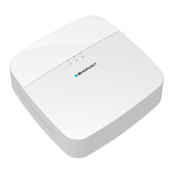
Page 4: Product Appearance
2. Product Appearance 2.1. NVR Rear Power supply port Ethernet Port VGA port Audio output port Audio input port HDMI port USB Port x2 2.2. Motherboard Serial ATA data port Serial ATA power port 1.1. Front NVR HDD status The red light becomes on when indictor light HDD is abnormal. -
Page 5: Internal Hdd Installation
2. Internal HDD Installation The specifications for the Internal Hard Drive must be the following: • Size: 3,5” • Minimum RPM 7200 • Maximum capacity of 6TB. • We recommended to use optimized HDD for surveillance as “Western Digital Purple” or “Seagate Surveillance HDD”. We strongly do not recommend to use a standard PC HDD, since a standard HDD is not ready to work 24/7 and the HDD might stop working due to the very high workload. -
Page 6: Local Operation
3. Local Operation Installation 3.1. Step 1: Turn ON the NVR. Connect the power supply to the power supply port. Step 2: Connect the power supply cable to the power socket. The 3 Red Indicator lights will turn on and the device will start booting. Step3: Connect the NVR to the router with an Ethernet cable. - Page 7 4.2.2 Launching the VIO-Web Player and performing a network scan 1. Launch the Cam4Home-Desktop-Web Player click “confirm” to start the network scan to find the Blaupunkt NVR in the network. (The network scan usually takes 10-60 seconds dependent on the networks performance) 2.
- Page 8 6. NVR 1 time configuration explained on this manual. For the “Back” function use the right click of the There are 2 ways to config the NVR for the first time: Web Interface: Log in through the web interface (point 5. Web Interface Operation) ...
-
Page 9: Security Question
Security question Input an email on the first field if you desire to have a recovery password method, otherwise click on the checkbox to deactivate recovery password function. Select and answer 3 security questions. Then click next and OK on the next window. Email: Input an email address for reset password purpose. - Page 10 General settings Setup the General, Date/time and Holiday tab settings according to your needs. Note: Local operation and web interface option may differ. Images are as reference only. General 6.3.1 Set device basic information such as device name, serial number and etc Device Name: Input a corresponding device name here.
- Page 11 6.3.2 Date & Time Here you can set device time. You can enable NTP (Network Time Protocol) function so that the device can sync time with the NTP server. Important: Stop record operation before making any modification. System time: Set the system time according to your Time Zone. Default time ...
- Page 12 6.3.3 Holiday Here you can add, edit, delete holiday. After you successfully set holiday information, you can view holiday item on the record and snapshot period. Step 1 Click Holiday button. Step 2 Click Add new holiday button, device displays the following interface. Step 3 Set holiday name, repeat mode and holiday mode.
- Page 13 6.5 Basic Network Settings On the Smart Wizard this step will appear only on under Local operation. By default the NVR is configured via DHCP. Click the pencil icon to edit the NVR network settings. IP Version: There are two options IP formats: IPv4 and IPv6. ...
- Page 14 Click “device search” to perform a network scan looking for configured Blaupunkt VIO cameras or ONVIF cameras on the network. (The cameras need to be connected to the network before performing the scan). To add cameras to the NVR click on the left check box and select the desired cameras.
- Page 15 4. Click the pencil icon to open the quick connection setting for the camera: Cam Name: Write the name for the camera (E.g. B30-Front Door). When streaming or recording this name will be displayed on the bottom left. IP Address: Camera IP Address. ...
- Page 16 Note: If the cameras are still offline after changing the password review the password. If the problem persist it might be a network issue that doesn’t allows the NVR to communicate with the camera. 6. Once all the cameras are displayed with the status connected click the Next button. After a camera is added the NVR is able to receive, storage, and manage the video streams of the cameras.
- Page 17 Cameras recording The NVR will record video or snapshots according to this configurations. There are 4 recording types: Continuous (green): The NVR will record continuously during the selected time. MD ( yellow): The NVR will start recording only if Motion Detection is detected. Please refer to chapter XXXXX to learn more about Motion detection.
- Page 18 4. Input a starting and ending time for the time period. 5. Select one or more record types for the desired period. 6. It’s possible to config up to six different periods per day. 7. At the bottom select the desired days for that period. Note: The day that was selected on step 2 is mandatory, to exclude it go back and select a different day at step 2.
- Page 19 Cameras event configuration If the “Enable” box is checked means that a camera is detected on that channel. Otherwise it will mean that no camera is active on that channel and configuration is not possible. To change the settings of a camera click on the dropdown menu and select the desired camera / channel.
-
Page 20: Nvr Settings
To add cameras follow the steps listed below. 1. Click “device search” to perform a network scan looking for configured Blaupunkt VIO cameras or ONVIF cameras on the network. (The cameras need to be connected to the network before performing the scan). - Page 21 4. Click the pencil icon to open the quick connection setting for the camera: Cam Name: Write the name for the camera (E.g. B30-Front Door). When streaming or recording this name will be displayed on the bottom left. IP Address: Camera IP Address. ...
- Page 22 Note: If the cameras are still offline after changing the password review the password. If the problem persist it might be a network issue that doesn’t allows the NVR to communicate with the camera. 6. Once all the cameras are displayed with the status connected click the Next button. After a camera is added the NVR is able to receive, storage, and manage the video streams of the cameras.
- Page 23 7.1.1 . 2 Status Here you can view the IPC status of the corresponding channel such as motion detect, video loss, tampering, alarm and etc. See Figure 4-55. IPC status: : Front-end does not support. : Front-end supports. There is alarm event from current front-end. Connection status: : Connection succeeded.
- Page 24 From main menu->setting->camera->remote, the interface is shown as below. 7.1.1.4 Upgrade Step 1 Download the latest manual for your cameras from Blaupunkt download center: https://www.blaupunkt.com/en/nc/servicesupport/downloads/ Step 2 Go to your “Downloads” folder and look for the Firmware file. The file Firmware will be downloaded as a Zip (compressed folder).
- Page 25 7.1.2 Image It is to set network camera parameters according to different environments. It is to get the best video effect. From main menu->setting->camera->image, you can see the image interface is shown as below. Click on the channel drop-down menu and select the desired camera. Image settings options will change according to the selected camera model.
- Page 26 Auto Iris: It is for the device of the auto lens. You can check the box before ON to enable this function. The auto iris may change if the light becomes different. When you disable this function, the iris is at the max. System does not add the auto iris function in the exposure control.
-
Page 27: Encode Mode
7.1.3 Encode It is to set video encode parameters such as video bit rates, video overlay, snapshot settings 7.1.3.1 Encode mode It is to set IPC encode mode, resolution, bit stream type and etc. From Main menu->Setting->System->Encode, you can see the following interface. Click on the channel drop-down menu and select the desired camera. - Page 28 Compression: Video encode mode. H.264: Main Profile encode mode. H.264H: High Profile encode mode. H.264B: Baseline Profile encode mode. H.265: Main Profile encode mode. MJPEG: System needs high bit streams to guarantee video definition. Use the ...
- Page 29 7.1.3.2 Overlay Click overlay button, you can see an interface is shown in the picture bellow. Click on the channel drop-down menu and select the desired camera. Overlay settings options will change according to the selected camera model. Cover area: Here is for you to cover area section. You can drag you mouse to set proper ...
- Page 30 7.1.3.1 Snapshot Here you can set snapshot mode, picture size, quality and frequency. Click on the channel drop-down menu and select the desired camera. Snapshot settings options will change according to the selected camera model. Snapshot mode: There are two modes: regular and trigger. If you set regular mode, you need to ...
-
Page 31: Camera Name
7.1.4 Camera Name From main menu->Setting->Camera-Channel name, you can see an interface shown as bellow. It is to modify channel name. It max supports 63-character. Please note you can only modify the channel name of the connected network camera. - Page 32 7.2 Network 7.2.1 TCP/IP The single network adapter interface is shown as bellow. Network Mode : Includes multiple access, fault tolerance, and load balancing Multiple-address mode: eth0 and eth1 operate separately. You can use the services such as HTTP, RTP service via etho0 or the eth1.
- Page 33 MAC address: The host in the LAN can get a unique MAC address. It is for you to access in the LAN. It is read-only. IP address: Here you can use up/down button () or input the corresponding number to ...
- Page 34 7.2.2 PORT The connection setup interface is shown as bellow Max connection: The max client login amount (such as WEB, platform, cellphone and etc). The value ranges from 1 to 128(default). TCP port: Default value is 37777. UDP port: Default value is 37778. ...
- Page 35 7.2.3 DDNS DDNS (Dynamic Domain Name Server) is to dynamically refresh the DNS domain name and IP address if the device IP address has changed frequently. The user can use the domain to access the device. Preparation Before the operation, make sure the device supports DNS type and go to the DDNS service provider website to register the domain name via the PC.
- Page 36 7.2.4 E-mail The email interface is shown as below. SMTP server: Please input your email SMTP server IP here. Port: Please input corresponding port value here. User name: Please input the user name to login the sender email box. ...
- Page 37 7.2.5 P2P The NVR will display two QR codes. We recommend taking a screenshot of this QR codes since they will be useful in the future to config the Cam4Home App. Then click “next”. P2P must be enabled to work with the app Cam4Home. For more info regarding Cam4Home app please refer to menu XXXXXXXXXX You can use your cell phone to scan the QR code and add it to the cell phone client.
-
Page 38: Video Detection
7.3 Events 7.3.1 Video Detection The video detect adopts the computer image and graphics process technology. It can analyse the video and check there is considerable changing degree or not. Once video has changed considerably (such as there is any moving object, video is distorted), system can trigger the corresponding alarm activation operations. - Page 39 Region: Click select button, the interface is shown as bellow. Here you can set motion detection zone. There are four zones for you to set. Please select a zone first and then left drag the mouse to select a zone. The corresponding colour zone displays different detection zone.
- Page 40 There are four record types: regular, motion detection (MD), Alarm, MD & alarm. Anti-dither: Here you can set anti-dither time. The value ranges from 5 to 600s. The anti-dither time refers to the alarm signal lasts time. It can be seem as the alarm signal activation stays such as the buzzer, tour, PTZ activation, snapshot, channel record.
- Page 41 Tour: Here you can enable tour function when alarm occurs. System one-window tour. Snapshot: You can enable this function to snapshot image when a motion detect alarm occurs. Video matrix Check the box here to enable this function. When an alarm occurs, SPOT OUT port ...
- Page 42 7.3.2 Alarm In the main menu, from Setting->Event->Alarm, you can see alarm setup interface. Alarm in: Here is for you to select channel number. In the main menu, from Setting->Event->Alarm, you can see alarm setup interface. Local alarm: After connect the alarm device to the NVR alarm input port, system can trigger the ...
- Page 43 IPC external alarm: When the network camera connected peripheral device has triggered an alarm, it can upload the alarm signal to the NVR via the network transmission. The system can trigger the corresponding alarm operations. IPC offline alarm: When the network connection between the NVR and the network camera is off, ...
- Page 44 Enable: Please you need to highlight this button to enable current function. Type: normal open or normal close. Period: Click set button, you can see an interface is shown below. There are two ways for you to set periods. There are max 6 periods in one day. There are four record types: regular, motion detection (MD), Alarm, MD &...
- Page 45 Anti-dither: Here you can set anti-dither time. The value ranges from 5 to 600s. The anti-dither time refers to the alarm signal lasts time. It can be seem as the alarm signal activation stays such as the buzzer, tour, PTZ activation, snapshot, channel record. The stay time here does not include the latch time.
- Page 46 7.3.3 Abnormally There are three types: Disk: Disk error, no disk, no space. Network: Disconnection, IP conflict, MAC conflict. User: Illegal login. ...
- Page 47 Alarm output: Please select alarm activation output port (multiple choices). Less than: System can alarm you when the HDD space is less than the threshold you set here (For HDD no space type only). Attempts: In user interface, select illegal login from the dropdown list. Here you can ...
- Page 48 7.4 Storage Here you can view HDD information such as type, status, total capacity, record time and etc. The operation includes format, resume from error, change HDD property (Read write, Read- only). Here you can also set alarm and HDD storage position. 7.4.1 Basic It is to manage HDD storage space.
-
Page 49: Hdd Capacity Calculation
7.4.1.1 HDD capacity calculation Calculate total capacity needed by each device according to video recording (video recording type and video file storage time). Step 1: According to Formula (1) to calculate storage capacity that is the capacity of each channel needed for each hour, unit Mbyte. ÷... - Page 50 7.4.2 Schedule The NVR will record video or snapshots according to this configurations. There are 4 recording types: Continuous (green): The NVR will record continuously during the selected time. MD ( yellow): The NVR will start recording only if Motion Detection is detected. Please refer to chapter XXXXX to learn more about Motion detection.
- Page 51 12. A new window will pop-up with the working period interface. 13. Input a starting and ending time for the time period. 14. Select one or more record types for the desired period. 15. It’s possible to config up to six different periods per day. 16.
-
Page 52: Hdd Manage
7.4.3 HDD Manage It is to view and sett HDD properties and format HDD. It is to view current HDD type, status, capacity and etc. The operation includes format HDD, and change HDD property (read and write/read-only/redundancy). To prevent files be overwritten in the future, you can set HDD as read-only. ... -
Page 53: Hdd Detect
7.4.4 HDD Detect The HDD detect function is to detect HDD current status so that you can clearly understand the HDD performance and replace the malfunction HDD. There are two detect types: Quick detect is to detect via the universal system files. System can quickly complete ... - Page 54 Click View, you can see the detailed information such as detect result, backup and S.M.A.R.T.
- Page 55 7.5 System 7.5.1 General Setup the General, Date/time and Holiday tab settings according to your needs. Note: Local operation and web interface option may differ. Images are as reference only. 7.5.1.1 General Set device basic information such as device name, serial number and etc Device Name: Input a corresponding device name here.
- Page 56 7.5.1.2 Date&Time Here you can set device time. You can enable NTP (Network Time Protocol) function so that the device can sync time with the NTP server. Important: Stop record operation before making any modification. System time: Set the system time according to your Time Zone. Default time ...
- Page 57 7.5.1.3 Holiday Here you can add, edit, delete holiday. After you successfully set holiday information, you can view holiday item on the record and snapshot period. Step 7 Click Holiday button. Step 8 Click Add new holiday button, device displays the following interface. Step 9 Set holiday name, repeat mode and holiday mode.
- Page 58 7.5.2 Display 7.5.2.1 Display From Main Menu->Setting->System->Display->Display, you can go to the following interface. Here you can set menu and video preview effect. All you operation here does not affect the record file and playback effect. Now you can set corresponding information. Resolution: There are five options: 1280×1024 (Default), 1280×720, 1920×1080, ...
- Page 59 7.5.2.2 Preview Tour Parameters Set preview display mode, channel display sequence and tour setup. Set preview display mode: On the preview interface, right click mouse, you can view right- click menu. Now you can select preview window amount and channel. Set channel display mode: On the preview interface, if you want to change channel 1 and ...
- Page 60 7.5.3 Voice Prompt 7.5.4 Account It is to manage users, user group and ONVIF user, set admin security questions. Note For the user name, the string max length is 31-byte, and for the user group, the string max length is 15-byte. The user name can only contain English letters, numbers and “_” 、“@”、“.”.
- Page 61 Step 2 Click Add user button. Step 3 Input the user name, password, select the group it belongs to from the dropdown list. Then you can check the corresponding rights for current user. Note For convenient user management, usually we recommend the general user right is lower than the admin account.
- Page 62 7.5.4.1.1 Modify User From main menu->Setting->System->Account->User, click , you can go to the following interface to change user information. For admin user, you can change the email, enable/disable unlock pattern, change password prompt question, set security questions.
- Page 63 Input email information and then click Save, it is to set/change email address. Check the box to enable unlock pattern and then click , click Save to change unlock pattern. Set security question Step 1 Click Security question, enter the following interface. Step 2 Input answers and then click Save button.
- Page 64 7.5.4.1 Group 7.5.4.1.1 Modify Group Step 1 From main menu->Setting->System->Account->Group. Enter add group interface. Step 2 Click add group button. Step 3 Input group name and then input some memo information if necessary. Check the box to select authorities.
- Page 65 7.5.4.1 Security Question Note: This function is for admin user only. Here you can change security questions. After you successfully answered security questions, you can reset admin account password. From main menu->Setting->System->Account->Security question, the interface is shown as below. Input correct security answers and then click Delete button at the bottom of the interface, you can reset security questions and answers.
- Page 66 7.5.4.1 ONVIF User When the camera from the third party is connected with the DVR via the ONVIF user, please use the verified ONVIF account to connect to the DVR. Here you can add/delete/modify user Note The default ONVIF user is admin. It is created after you initialize the DVR. Step 1 From main menu->Setting->System->Account->ONVIF User.
-
Page 67: Auto Maintenance
7.5.5 Security 7.5.4 Auto Maintenance Here you can set auto-reboot time and auto-delete old files setup. You can set to delete the files for the specified days. You can select proper setup from dropdown list. After all the setups please click save button, system goes back to the previous menu. - Page 68 7.5.4 Imp/exp This function allows you to copy current system configuration to other devices. It also supports import, create new folder, and delete folder and etc function. From Main menu->Setting->System->Import/Export, you can see the configuration file backup interface is shown as below. Export: Please connect the peripheral device first and then go to the following interface.
- Page 69 7.5.5 Default Warning! After you use default function, some your customized setup may lose forever! Please think twice before you begin the operation! You can restore factory default setup to fix some problems when the device is running slowly. Configuration error occurred. From Main menu->Setting->System->Default, you can go to the default interface.
- Page 70 7.5.6 Upgrade Step 1 Download the latest Firmware version for the NVR from our webpage: https://www.blaupunkt.com/en/nc/servicesupport/downloads/. Step 2 Unzip the zip file. File name should be XXXXX.bin. Step 3 Go to Settings System Upgrade Step 4 If the installation is done via web interface forward to step 5. If the upgrade is done via the NVR display refer to “Upgrade via NVR display”...
-
Page 71: Live Stream
8. Live Stream After device booted up, the system is in multiple-channel display mode. The amount of cameras that can be registered on the NVR is limited to the amount of channels from the NVR. It is not possible to add more than 4 cameras for a 4 channel NVR (e.g. -
Page 72: Preview Control Interface
8.1 Window split mode While on live view interface use the mouse right click and select the desired window split mode. From left to right: View 1: Full screen single camera. Select the desired camera to be displayed. View 4: Display divided equally in 4 windows for 4 cameras. Select channels 1-4 or 5- ... -
Page 73: Manual Snapshot
8.2.2 Zoom Zoom in specified zone of current channel. It supports zoom in function of multiple- channel. There are two ways for you to zoom in: Put the middle button at the center of the zone you want to zoom in and use the ... - Page 74 8.3 PTZ Before you control the PTZ, please make sure the PTZ decoder and the NVR network connection is OK and the corresponding settings are right. 8.3.1 PTZ Settings Cable Connection Please follow the procedures below to go on cable connection Connect the dome RS485 port to NVR RS485 port.
-
Page 75: Ptz Control
8.3.2 PTZ Control After completing all the setting please click save button. Right click mouse (click “Fn” Button in the front panel or click “Fn” key in the remote control). Please note you can only go to the PTZ control interface when you are in 1- window display mode. - Page 76 Name Function function Shortcut Function function Shortcut Zoom Near Focus Near ► │ │ Iris close Open Click to open the menu, you can set preset, tour, pattern, scan and etc. Please note the above interface may vary due to different protocols. The button is grey and cannot be selected once the current function is null.
-
Page 77: Ptz Function Setup
8.3.2.1 PTZ function setup Click , you can go to the following interface to set preset, tour, pattern, and scan. Preset Setup Click preset button and use eight direction arrows to adjust camera to the proper position. Click Set button and then input preset number. -
Page 78: Call Ptz Function
Scan Setup Click Scan button. Use direction buttons to set camera left limit and then click Left button. Use direction buttons to set camera right limit and then click Right button. Now the scan setup process is complete. 8.3.2.2 Call PTZ Function Call Preset: Input preset value and then click to call a preset. -
Page 79: Display Window
9 Playback 9.1 Playback and Search From Main menu->Search, or on the preview interface right click mouse and then select search item, you can go to the following interface. 9.1.1 Display window Here is to display the searched picture or file. Support 1/4/8 playback. -
Page 80: Playback Image
9.1.2.1 Playback Image Here you can search and play the image. Please follow the steps listed below. Step 1 From main menu->Search, or on the preview window right click mouse and then click Search, you can go to the search interface. Step 2 At the top right corner, select image and then input playback interval. - Page 81 9.1.7 File list switch button Double click it, you can view the picture/record file list of current day. The file list is to display the first channel of the record file. The system can display max 128 files in one time. Use the │and │...
-
Page 82: Playback Control
9.1.8 Playback Control Play/Pause 、 In slow play mode, click it to switch between play/pause. Backward play In normal play mode, left click the button, the file begins backward play. Click it again to pause current play. In backward play mode, click to restore normal play. -
Page 83: Smart Search Playback
9.1.8.1 Smart Search Playback During playback process, it can analyze the motion detect zone in the scene and give the analysis result. This function is for channel that already enabled motion detect function (main menu- >Setting->Event->Video detect->Motion detect). Please follow the steps listed below. (This function is for some series product only) Step 1 Select a channel to playback video and then click . - Page 84 Note: Usually, system can playbacks previous N seconds record if there is such kind of record file. Otherwise, system playbacks from the previous X seconds when there is such as kind of record. Mark Manager Click the mark manager button the Search interface;...
-
Page 85: Time Bar Unit
9.1.10 Time bar unit • The option includes: . The smaller the 、 、 和 unit, the larger the zoom rate. You can accurately set the time in the time bar to playback the record. • The time bar is beginning with 0 o'clock when you are setting the configuration. - Page 86 9.1.13 Clip This function allows you to clip some footages to a new file and then save to the USB device. Please follow the steps listed below. Step 1 Select a record first and then click to playback. Step 2 Select a time at the time bar and then click to start clip, Step 3 Select a time at the time bar and then click to stop clip,...
-
Page 87: Digital Zoom
System supports 1/4/8-split mode. Slight different may be found here. The 4-channel series product supports 4-split mode. The 8-channel series product support 8-split mode. The min period of each section is 5 minutes. For the record is less than 20 minutes, if you ... - Page 88 10 FAQ & Maintenance Questions Solutions NVR cannot boot up Input power is not correct. properly. Power connection is not correct. Power switch button is damaged. Program upgrade is wrong. HDD malfunction or something wrong with HDD ribbon. ...
- Page 89 Questions Solutions Front panel PTZ error PTZ decoder setup, connection or installation is not correct. Cable connection is not correct. PTZ setup is not correct. PTZ decoder and NVR protocol is not compatible. NVR cannot control PTZ. PTZ decoder and NVR address is not compatible.
- Page 90 Questions Solutions Alarm setup is not correct. Alarm signal cannot Alarm output has been open manually. been disarmed. Input device error or connection is not correct. Some program versions may have this problem. Please upgrade your system. Alarm setup is not correct.
-
Page 91: Daily Maintenance
Questions Solutions Please make sure the IPC has booted up. IPC network connection is right and it is online IPC IP is in the blacklist. The device has connected to the too many IPC. It cannot I can not connect to the ... -
Page 92: Technical Support
11 Technical Support For more information on panel and devices, please visit www.blaupunkt.com/service Blaupunkt Competence Center Security & Care www.blaupunkt.com Security Brand Pro GmbH Mondstrasse 2-4 85622 Feldkirchen-München, Germany © Technical changes and errors excepted NOTE: This quick start guide is for reference only. Slight difference may be found in the user interface.
Need help?
Do you have a question about the VIO-NVR40 and is the answer not in the manual?
Questions and answers