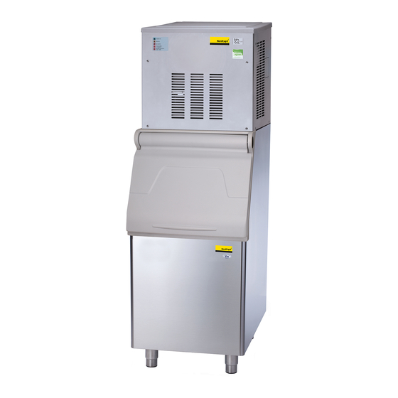
Nordcap SPN 125 Service Manual

R134a/r404a electronic modular flakers and superflakers

Advertisement

SERVICE MANUAL
SPN 125
SPN 255
SPN 405
SPN 605
SPN 1205
R134A - R404A
Electronic Modular Flakers
and Superflakers

Advertisement

Table of Contents
loading

Summary of Contents for Nordcap SPN 125

  • Page 1 SERVICE MANUAL SPN 125 SPN 255 SPN 405 SPN 605 SPN 1205 R134A - R404A Electronic Modular Flakers and Superflakers...
  • Page 2: Table Of Contents

    Page 1 Table of contents page TABLE OF Specifications SPN 125 CONTENTS Specifications SPN 255 Specifications SPN 405 Specifications SPN 605 Specifications SPN 1205 GENERAL INFORMATION AND INSTALLATION Introduction Unpacking and Inspection - Ice maker Unpacking and Inspection - Storage bin...
  • Page 3 Page 2 SPECIFICATIONS ELECTRONIC MODULAR FLAKER MODEL SPN 125 Important operating requirements: • Air temperature 10°C (50°F) 40°C (100°F) • Water temperature 5°C (40°F) 35°C (90°F) • Water pressure 1 bar (14 psi) 5 bars (70 psi) • Electr. voltage •...
  • Page 4 HEIGHT (less legs) 525 mm. HEIGHT (with legs) 542 mm. WIDTH 563 mm. DEPTH 536 mm. WEIGHT 49 Kg. SPN 125 - MACHINE SPECIFICATIONS Water req. Model Cond. unit Comp. HP Finish lt/24 HR SPN 125 AS 120* S. Steel...
  • Page 5 Page 4 SPECIFICATIONS ELECTRONIC MODULAR FLAKER MODEL SPN 255 Important operating requirements: • Air temperature 10°C (50°F) 40°C (100°F) • Water temperature 5°C (40°F) 35°C (90°F) • Water pressure 1 bar (14 psi) 5 bars (70 psi) • Electr. voltage •...
  • Page 6 HEIGHT (less legs) 525 mm. HEIGHT (with legs) 542 mm. WIDTH 563 mm. DEPTH 536 mm. WEIGHT 49 Kg. SPN 125 - MACHINE SPECIFICATIONS Water req. Model Cond. unit Comp. HP Finish lt/24 HR SPN 125 AS 200* S. Steel...
  • Page 7 Page 6 SPECIFICATIONS ELECTRONIC MODULAR SUPERFLAKER MODEL SPN 405 Important operating requirements: • Air temperature 10°C (50°F) 40°C (100°F) • Water temperature 5°C (40°F) 35°C (90°F) • Water pressure 1 bar (14 psi) 5 bars (70 psi) • Electr. voltage •...
  • Page 8 Page 7 SPECIFICATIONS Dimensions: HEIGHT (less legs) 645 mm. HEIGHT (with legs) 650 mm. WIDTH 538 mm. DEPTH 663 mm. WEIGHT 77 Kg. SPN 405 - MACHINE SPECIFICATIONS Water req. Model Cond. unit Finish Comp. HP lt/24 HR SPN 405 AS 320* S.
  • Page 9 Page 8 SPECIFICATIONS ELECTRONIC MODULAR SUPERFLAKER MODEL SPN 605 Important operating requirements: • Air temperature 10°C (50°F) 40°C (100°F) • Water temperature 5°C (40°F) 35°C (90°F) • Water pressure 1 bar (14 psi) 5 bars (70 psi) • Electr. voltage •...
  • Page 10 Page 9 SPECIFICATIONS Dimensions: HEIGHT (less legs) 785 mm. HEIGHT (with legs) 790 mm. WIDTH 538 mm. DEPTH 663 mm. WEIGHT 93 Kg. SPN 605 - MACHINE SPECIFICATIONS Water req. Model Cond. unit Finish Comp. HP lt/24 HR SPN 605 AS 600* S.
  • Page 11 Page 10 SPECIFICATIONS ELECTRONIC MODULAR SUPERFLAKER MODEL SPN 1205 Important operating requirements: • Air temperature 10°C (50°F) 40°C (100°F) • Water temperature 5°C (40°F) 35°C (90°F) • Water pressure 1 bar (14 psi) 5 bars (70 psi) • Electr. voltage •...
  • Page 12 Page 11 SPECIFICATIONS Dimensions: HEIGHT 850 mm. WIDTH 1065 mm. DEPTH 698 mm. WEIGHT 179 Kg. SPN 1205 - MACHINE SPECIFICATIONS Water req. Model Cond. unit Comp. HP Finish lt/24 HR SPN 1205 AS 1150* S. Steel SPN 1205 WS Water 8000* Basic electr.
  • Page 13: General Information And Installation

    Page 12 GENERAL INFORMATION AND INSTALLATION INTRODUCTION On models SPN 125, SPN 255, SPN 405- 605 remove the front/top panel while on model SPN 1205 remove top and sides panels of the unit This manual provides the specifications and the and inspect for any concealed damage.
  • Page 14: Location And Levelling

    Page 13 Level the Storage Bin Assy in both the left to right and front to rear directions by means of the adjustable legs. On R 155 and R 250 Storage Bin inspect its top mounting gasket which should be flat with no wrinkles, to provide a good sealing when the RP 155/250 Top Cover is installed on top of it.
  • Page 15: Electrical Connections

    Page 14 Open all the way the lift door in the upright fitting and a shut-off valve installed in an accessible position then place the door catch on the front position between the water supply line and the face of the ice maker and tape it in place. unit.
  • Page 16: Installation Practice

    Page 15 Has the voltage been tested and checked Have the bin liner and cabinet been wiped clean? against the data plate rating? 10. Has the owner/user been given the User Has the water supply pressure been Manual and been instructed on the importance checked to ensure a water pressure of at least 1 of periodic maintenance checks? bar (14 psi).
  • Page 17: Operating Instructions

    Page 16 OPERATING INSTRUCTIONS Elapsed the 3 minutes - stand by period - START UP the unit starts operating with the activation in sequence of the following assemblies: After having correctly installed the ice maker and completed the plumbing and electrical GEAR MOTOR/S connections, perform the following “Start-up”...
  • Page 18 Page 17 FIG. 2 WATER LEVEL RESET GEAR MOTOR ROTATION CONTACTOR COIL RELAYS CONDENSER TEMP. T 40÷50°C EVAPORATOR TEMP. GEAR MOTOR ICE LEVEL CONTROL TRIAC FAN MOTOR TRANSF. ELECTRONIC CARD FIG. 3 WATER LEVEL RESET GEAR MOTOR ROTATION CONTACTOR COIL RELAYS CONDENSER TEMP.
  • Page 19: Operational Checks

    Page 18 NOTE. On air cooled models, the condenser NOTE. If, after ten minutes from the compressor start-up, the evaporating tem- temperature sensor, which is located within perature has not dropped down to a value the condenser fins, keeps the head °...
  • Page 20 Page 19 Opening the water supply line shutoff valve to fill This will cause a gradual decrease of the water up again the float reservoir, the YELLOW LED level in the float reservoir and as soon as the goes off while the RED LED starts blinking. level gets below the two vertical metal pins, the After 3 minutes the unit resumes its total operation flaker stops to operate and the YELLOW warning...
  • Page 21 Page 20 If previously installed, remove the refrigerant NOTE. The ICE LEVEL CONTROL service gauges and re-fit the unit service panels (INFRARED SYSTEM) is independent of the previously removed. temperature however, the reliability of its detection can be affected by external light radiations or by any sort of dirt and scale Instruct the owner/user on the general sediment which may deposit directly on the...
  • Page 22: Principle Of Operation (How It Works)

    Page 21 PRINCIPLE OF OPERATION WATER CIRCUIT SPN 125-255 ICE SPOUT The water enter in the machine through the water inlet fitting which incorporates a strainer - FLOAT TANK located at the rear side of the cabinet - then it...
  • Page 23: Refrigerant Circuit

    SPN1205), the unit stops after six seconds, 8.5 bar (120 psig) on SPN 125 and of 17 bar with the simulteneous glowing of the YELLOW (240 psig) on SPN 255-405-605 and SPN 1205 LED signalling the “Full Bin”...
  • Page 24 Page 23 tube connected to the liquid refrigerant line. As The RED LED starts blinking and three pressure increases, the water regulating valve minutes later the flaker unit resume its normal opens to increase the flow of cooling water to the operating mode.
  • Page 25: Mechanical System

    Page 24 MECHANICAL SYSTEM RE-SET push button or switch OFF and ON the power line main disconnnect switch The mechanical system of the SIMAG Flaker (Fig. 7). machines consists basically of a gear motor assembly (two on model SPN1205) which drives, through a ratched coupling, a worn shaft or auger placed on its vertical axis within the freezing The machine will remain in OFF mode for...
  • Page 26: Operating Pressures

    NOTE. Before charging the refrigerant system Air cooled Water cooled always check the type of refrigerant and quantity as specified on the individual ice machine SPN 125 440 gr 400 gr dataplate. The refrigerant charges indicated are relatives to averages operating conditions.
  • Page 27: Components Description

    Page 26 COMPONENTS DESCRIPTION In the event the condenser temperature rises ° ° and reaches 60 C or 70 C according to the EVAPORATOR TEMPERATURE setting of DIP SWITCH number 8 the current SENSOR arriving to the micro processor is such to cause an immediate and total stop of the machine operation.
  • Page 28 Page 27 infrared sensor of ice level control - YELLOW LED YELLOW LED blinks fast) 6 seconds later the ice machine resumes Unit shut-off due to a its operation with the simul-taneous extinguishing too lo-water level into the 2nd YELLOW LED. float tank RED LED P.C.
  • Page 29 Page 28 the cooling coil with the evaporating chamber G. JUMPERS and in its interior is located the auger which The Flaker PC Board is equipped by three jumpers: rotates on its vertical axis and it is maintained J1 · TEST: Used in the factory to energise all aligned by the top and bottom bearings.
  • Page 30 Page 29 FAN MOTOR (Air cooled version) As pressure increases, the water regulating valve opens to increase the flow of cooling The fan motor is controlled through the TRIAC of water. the P.C. BOARD by the condenser temperature sensor. Normally it operates to draw cooling air through the condenser fins.
  • Page 31: Adjustment, Removal And Replacement Procedures

    Page 30 ADJUSTMENT, REMOVAL AND REPLACEMENT PROCEDURES REPLACEMENT OF EVAPORATOR NOTE. Read the instructions throughly TEMPERATURE SENSOR before performing any of the following adjustment or removal and replacement pro- Remove the front/top panel. cedure. Remove the insulation from the refrigerant tubing, connecting the freezer to the accumulator, to gain access to the sensor probe holder and pull it out .
  • Page 32: Replacement Of P.c. Board

    MAGNETIC SENSOR spout. On SPN 125- 255, SPN 405 -605 remove On the model SPN125-255 unthread the S.S. the front/top and side/rear panels and on SPN 1205 spout from the brass casting while on the other remove the front, top and left side panels.
  • Page 33: Replacement Of The Gear Motor Assy

    Page 32 Clean away the old grease from the interior 16. Install the upper bearing into the ice breaker of the ice breaker and inspect the bearing pressed starting by the radial portion that must be fitted into the top of the ice breaker and if worn do not with the flat surface facing up.
  • Page 34: Replacement Of Drier

    Page 33 On the models SPN125-255, SPN405-605 Unsolder and disconnect the capillary tube remove the bolts securing the fan motor bracket and the accumulator/suction line assy from the to the cabinet base and then remove the outlet line of the freezing cylinder. assembly.
  • Page 35: Replacement Of Water Cooled Condenser

    Page 34 REPLACEMENT OF WATER COOLED NOTE. It is imperative to install a replacement CONDENSER drier whenever the sealed refrigeration system is open. Do not replace the drier until Remove front/top and side/rear panels on all other repairs or replacements have been models SPN125-255, SPN405-605 and the front completed.
  • Page 36: Wiring Diagram

    Page 39 SERVICE DIAGNOSIS SYMPTON POSSIBLE CAUSE SUGGESTED CORRECTION Unit will not run Blown fuse in P.C.Board Replace fuse & check for cause of No LED lighted-on blown fuse Master switch in OFF position Turn switch to ON position Inoperative P.C.Board Replace P.C.Board Loose electrical connections Check wiring...
  • Page 37 Page 40 SERVICE DIAGNOSIS SYMPTON POSSIBLE CAUSE SUGGESTED CORRECTION Wet ice Ambient temperature too high Move unit to cooler location Under or overcharge of refrigerant Recharge with correct quantity High water level in the freezer Lower to approx. 20 mm below ice spout Faulty compressor Replace...
  • Page 38: Maintenance And Cleaning Instructions

    Page 41 MAINTENANCE AND CLEANING INSTRUCTIONS This should cause the immediate blinking of the GENERAL Bin Full YELLOW LED located in the front of P.C. Board and, 6 seconds later, the total stopping of The periods and the procedures for maintenance the ice maker with the simultaneous light up of and cleaning are given as guides and are not to the same LED (steady).
  • Page 39 Page 42 Remove the top panels to gain access to NOTE. The ice made with the cleaning the water reservoir. solution is slushy and coloured also, it may tend to loose fluidity creating some resistence Remove the float reservoir cover and with a in being elevated and extruded;...
  • Page 40 ELECTRONIC MODULAR FLAKERS AND SUPERFLAKERS SP SERIES CLEANING AND SANITIZING PROCEDURES TOOLS REQUIRED Medium Phillips Screwdriver Medium Flat Screwdriver Pair of Protective Gloves Bucket/Container Different types of brush Clean Cloth Ice Machine Cleaner/Sanitiser Antialgae Cleaner FREQUENCE WARNING. When using any chemical, protection of •...
  • Page 41 PROCEDURE 4. Remove the Front/Top panel and also……… Switch OFF the Master disconnect switch on the power line…. 2. Close water tap on the water supply line CLOSED NOTE. Be sure that no other equipment in use can 5. ……Side/Rear Panel to again to access…. suffer of the turn OFF of water.
  • Page 42: Cleaning Instructions Of Water System

    8. …..the water into a bucket then….. 6. ……..to the water reservoir. 9. ….place again the tube on the outlet port. 10. Prepare the cleaning solution by diluting in a plastic container two or three liters of warm Remove the metal clamp and disconnect the water (45°-50°C) with a 0,2-0,3 liters of Ice water tube from the outlet of the water reservoir.
  • Page 43 13. Leave machine mode WARNING. The Ice Machine Cleaner contains approximately 20 minutes so to have the Phosphoric Hydroxyacetic acids. These cleaning solution melting the scales into the compounds are corrosive and may cause burns if entire water system. swallowed, DO NOT induce vomiting. Give large amounts water milk.
  • Page 44 14. With the help of a brush dissolve the most 17. After 20 minutes switch ON the Master switch resistant and remote scale deposits into the to start the unit. plastic tube connecting the water reservoir to the bottom of the freezer. 18.
  • Page 45 21. When all the cleaning solution has been used 19. As soon as the level of the water into the water up, open the water shutoff valve to allow new reservoir is going down, slowly poor the fresh water to flow into the water reservoir. Let remaining cleaning solution till empty the bucket.
  • Page 46 27. Open the storage bin door in order to have 24. Remove the jumper between the two metal pins access to the storage bin and to the bottom of or …… the metal deflector. vvvvv 28. Place bucket with cleaning/sanitizing solution inside the storage bin (this allow you to freely clean/sanitize the bin) and with sponge clean/sanitize...
  • Page 47 30. Clean/sanitize the rear side of the bin door. 31. Re-fit the Side/Rear Panel and also ….. REMEMBER – To prevent the accumulation of undesirable bacteria it is necessary to sanitize the interior of the storage bin with an antialgae disinfectant solution EVERY WEEK NOTE –...

This manual is also suitable for:

Spn 255Spn 605Spn 1205Spn 405

Table of Contents