
Related Manuals for Lumag GF800


Summary of Contents for Lumag GF800
- Page 1 Distribution Limited Petrol Trencher Operator’s Manual GF800 FOR YOUR SAFETY READ AND UNDERSTAND THE ENTIRE MANUAL BEFORE OPERATING THIS MACHINE...
- Page 3 For the warranty to be valid the Warranty Registration Form must be completed and returned to Lumag Distribution Limited within 14 days of the purchase, together with a copy of the purchase invoice. We will use your email to confirm that we have received the completed Warranty Registration Form and contact you about any errors or omissions on the form.
- Page 5 All Other Moving Parts & Lubricate X (2) Cables 1 – First service only, 2 = Should be carried out by your Lumag Dealer, 3 = May need to be done more often in dusty areas & 4 = Replace paper element only...
-
Page 7: Table Of Contents
Table of Contents Table of Contents PART I: General Safety Rules ......................2 PART II: Familiar with Your Trencher ..................... 8 PART III: Operating the Trencher ....................10 PART IV: Maintaining Your Trencher ................... 16 PART V: Troubleshooting and Parts List ..................18 Conventions used in this manual WARNING This indicates a hazardous situation, which, if not avoided, could result in death or serious injury. -
Page 8: Part I: General Safety Rules
Part I: General Safety Rules PART I: General Safety Rules Safety Labels May Be Found on Your Unit... - Page 9 Part I: General Safety Rules WARNING This machine can cause serious injury to the operator and bystanders. The warning and safety instructions in this manual must be followed to provide reasonable safety and efficiency in using and storing. The operator is responsible for following the warnings and instructions in this manual and the trencher.
- Page 10 Part I: General Safety Rules Before using the Trencher NOTICE A. Operators must be fully trained before using this machine. B. User Manual is read and understood. C. Blades are in good condition and secure. All blades are sharpened or replaced in sets. D. All fasteners are checked for tightness. When using the Trencher WARNING A. Maintain strict discipline at all times and service machine at specified periods. B. Keep body parts, foreign objects and clothing clear of rotating auger and digging chain. C.
- Page 11 Part I: General Safety Rules Children are often attracted to the machine and the digging activity. Never assume that children will remain where you last saw them. Always follow these precautions: Keep children and pets at least 50 feet from the working area and ensure they are under the watchful care of a responsible adult.
- Page 12 Part I: General Safety Rules solutions to clean the air filter. The muffler and engine become very hot and can cause a severe burn; do not touch. General Safety WARNING Operating this Trencher safely is necessary to prevent or minimize the risk of death or serious injury.
- Page 13 Part I: General Safety Rules safe manner. Contact the dealers for assistance in your area.
-
Page 14: Part Ii: Familiar With Your Trencher
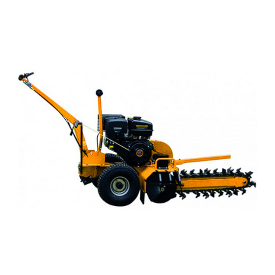
Part II: Familiar with Your Trencher PART II: Familiar with Your Trencher It may be helpful to familiarize yourself with the controls and features of the Trencher. If you have any question, please contact the dealers in your area. - Page 15 Part II: Familiar with Your Trencher TECHNICAL SPECIFICATIONS 600mm Trencher Engine 13/13.5/15HP four strokes Power Gasoline/petrol Trench Capacity 60m/hour Trench Width 100mm Trench Depth 200,400,600mm Blade 27 carbide alloy blades Chain Length 2000mm Chain Speed(Max) 550m/min Tire 145/7.0-6 Overall Height 1100mm Overall Length 2100mm Overall Width 720mm Weight 185kgs...
-
Page 16: Part Iii: Operating The Trencher
Part III: Operating the Trencher PART III: Operating the Trencher It may be helpful to better familiarize yourself with the features of your Trencher before beginning the steps outlined in this chapter. CAUTION A. Read and understand all instructions, safety precautions, and/or warnings listed in “PART I: General Safety Rules” before operating the TRENCHER. If any doubt or question arises about the correct or safe method of performing anything found in this manual, please contact the dealers in your area. Before loading and operating the Trencher, always wear protective gear, including safety goggles, hearing protection, tight-fitting gloves without draw strings or loose cuffs, and steel-toed shoes. Assembling Step 1: Assembling the handle system... - Page 17 Part III: Operating the Trencher Ref.No. Description Ref.No. Description main frame M16 bolt cotter pin lower handle shift handle and spring angle arm M8 bolt M8*20 hexagon bolt upper handle a. Secure lower handle(49) to the main frame(1) tightly. b. Assemble upper handle(47) to the lower handle(49), secure them with bolt(48) and angle arm(53) tightly.
- Page 18 Part III: Operating the Trencher Plug chain adapter(13) to the chain axle(2); Hold the chain(6) around chain adapter(13) and axle(2), then secure two head of the chain with chain pin(4) and chain lock(3); Secure bolt(55) until the chain is tight enough; Starting Be sure the depth control is in the “0” depth position and move both stop switches to the “ON”...
- Page 19 Part III: Operating the Trencher Trenching Be sure the digging chain is not turning when the engine is at an idle. Be sure the engine is off or at an idle before moving the trencher at the job site. Figure 1 WORK POSITION 600mm TRENCHER Depth “0”...
- Page 20 Part III: Operating the Trencher 3. Apply downward pressure to the handlebar so the digging chain is not in contact with the ground. Increase the engine speed and hold on to the handlebar with both hands. Slowly relieve the downward pressure on the handlebar allowing the digging chain to penetrate the soil until the chosen depth is reached.
- Page 21 Part III: Operating the Trencher A. Inspect entire trencher before each use. Replace damaged or worn parts. B. Check for fuel leaks and make sure all fasteners are in place and securely fastened. C. Replace digging blades that are severely worn. Be sure the digging chain and engine is not moving.
-
Page 22: Part Iv: Maintaining Your Trencher
Part IV: Maintaining The Thencher PART IV: Maintaining Your Trencher Regular maintenance is the way to ensure the best performance and long life of your machine. Please refer to this manual and the engine manufacturer's user manual for maintenance procedures. Maintenance Safety NOTICE A. Before performing any maintenance procedure or inspection, stop the engine, wait five minutes to allow all parts to cool. - Page 23 Part IV: Maintaining The Thencher Lubrication NOTICE All Bearings of Trencher are sealed units and should have sufficient lubricant to last the life of your machine with normal use. Transportation and Storing NOTICE A. Always shut off the fuel valve and engine. B. Always allow the engine to cool. C.
-
Page 24: Part V: Troubleshooting And Parts List
Part VI: Troubleshooting and Parts List PART V: Troubleshooting and Parts List Most problems are easy to fix. Consult the Troubleshooting Table below for common problems and their solutions. If you continue to experience problems, contact the dealers in your area. WARNING Before performing any maintenance procedure or inspection, stop the engine, wait five minutes to allow all parts to cool. - Page 25 Part VI: Troubleshooting and Parts List Explosion View and Parts List 1. Chain System Ref.No. Description Ref.No. Description main frame chain spacer chain axle plate 6204 bearing chain lock front gear cotter pin M20 nut blade Pole fixation chain adapter Protect pole chain gear cap M20 bolt...
- Page 26 Part VI: Troubleshooting and Parts List 2. Gear System Ref.No. Description Ref.No. Description main frame taper bearing flange spacer chain axle plate taper bearing upper part ridge taper bearing base ridge spacer 70 seal back gear 72 outer circlip gear axle taper bearing spacer 8*7 keyway gear wheel 8*7 keyway M30 screw nut...
- Page 27 Part VI: Troubleshooting and Parts List 3. Drive System Ref.No. Description Ref.No. Description main frame pulley Front gear 5*5 keyway gear wheel pulley axle drive chain bearing clutch bearing cover belt Inner belt cover belt cover...
- Page 28 Part VI: Troubleshooting and Parts List 4. Depth Control System Ref.No. Description Ref.No. Description main frame shift deck chain axle plate cotter pin shift rod shift handle Depth control handle shift handle spring Transfer pole M8 bolt...
- Page 29 Part VI: Troubleshooting and Parts List 5. Main Frame Ref.No. Description Ref.No. Description main frame lower handle cotter pin 20 washer handle cover wheel throttle cable butter bean upper handle angle arm M16 bolt flameout switch...
- Page 30 Part VI: Troubleshooting and Parts List 6. Ratchet Assembly Ref.No. Description Ref.No. Description cotter pin M10 nut M20 bolt halt frame M12 bolt spring M12 nut M10 nut ratchet wheel M10 bolt M10 headed screw...
- Page 31 Part VI: Troubleshooting and Parts List Part List: Ref.No. Description Ref.No. Description main frame bearing cover chain axle plate shift handle chain lock shift handle spring cotter pin M8 bolt blade shift deck chain M20 bolt shift rod gear cap handle cover chain spacer throttle cable 6204 bearing upper handle front gear...
- Page 32 Unit 10, Hatchmoor Industrial Estate, Hatherleigh, Okehampton, Devon EX20 3LP www.lumag-gb.co.uk 01837 811741 Lumag Distribution Limited Company Number: 09267547 VAT Number: GB154566788 Hatherleigh Plant and Tool Hire is a trading name of Lumag Distribution LTD...
Need help?
Do you have a question about the GF800 and is the answer not in the manual?
Questions and answers