
Related Manuals for Vivax vLoc3-5000


Summary of Contents for Vivax vLoc3-5000
- Page 1 Locators & Supplies, Inc. (800) 950-6666 sales@locatorsandsupplies.com www.locatorsandsupplies.com vLoc3-5000 User Handbook (English Edition) Version V1.2 P/N:4.04.000106...
-
Page 2: Table Of Contents
American & Canadian Safety Notices .......................3 2. Service & Support ...............................4 Serial Number and Software Revision Number ..................4 Distributors and Service Centers Closest to You:..................5 3. vLoc3-5000 Receiver ............................6 vLoc3-5000 Receiver Overview ........................6 Charging the Receiver Batteries .......................7 vLoc3-5000 Receiver Keypad........................8 User Menu ..............................8... - Page 3 3.6.2 Shallow Cable..........................12 3.6.3 Swing Alert..........................12 3.6.4 Overhead cable .........................12 vLoc3-5000 Receiver Locate Screen Shots ...................13 Classic Locating Modes (Response) ......................15 3.8.1 Peak Response Mode .......................15 3.8.2 Broad-Peak Mode ......................15 3.8.3 Null Mode ..........................16 3.8.4 Delta Null ..........................16 3.8.5 Omni-Peak Response Mode .....................16...
- Page 4 7. Using Accessories ............................61 Using the LPC Separation Filter ......................61 Using the Analogue A-frame Fault Finding Accessory ................61 Using the vLoc3-5000 SiS Remote Antenna ..................64 Using the SIS Signal with the Remote Antenna to help identify a cable ..........66 Signal Select Clamp........................69 7.4.1...
- Page 5 8.14 Live Plug Connector (LCC) ........................74 8.15 vLoc3-MLA (Marker Locator Adapter) ....................74 9. Glossary ................................75 ™...
-
Page 6: General Safety & Care Information
● Do not assume that if the plug fits it is the correct charger – a charger with the correct part number must be used – just because it is a Vivax-Metrotech charger and the plug fits does not mean it is the correct charger. -
Page 7: Lithium-Ion Batteries (Rechargeable)
Please contact Vivax-Metrotech Customer Service (USA 1-800-446-3392, International +1-408-734-1400, USA Pacific Time Zone) for more details. ● Vivax-Metrotech vLoc Series 2 products using Lithium-Ion battery are classified as "not restricted" they can be shipped normally by road/rail/sea & air (passenger & freight aircraft) without restrictions. -
Page 8: Care Of Equipment
● Operation is subject to the following two conditions: (1) this device may not cause interference, and (2) this device must accept any interference that may cause undesired operation of the device. EUROPE ● Vivax-Metrotech confirms that the location system is compliant with relevant provision of European directive 1999/5/EC. ο EN 55011 ο... -
Page 9: Service & Support
Service & Support 2. Service & Support 2.1 Serial Number and Software Revision Number Always quote your receiver and transmitter model number, serial number and software revision number when requesting product support. They can be found as follows: (for reference only). Model &... -
Page 10: Distributors And Service Centers Closest To You
Santa Clara, CA 95054, USA Website: www.vivax-metrotech.com T/Free : 800-624-6210 Sales & Sales Support: : +1-408-734-1400 T/Free : 800-446-3392 : +1-408-743-5597 : +1-408-734-1400 Website : www.vivax-metrotech.com : +1-408-734-1415 Email : VentasparaAmericaLatina@vxmt.com Email : sales@vxmt.com China Service & Repairs: Leidi Utility Supply (Shanghai) Ltd. T/Free : 800-638-7682 No. -
Page 11: Vloc3-5000 Receiver
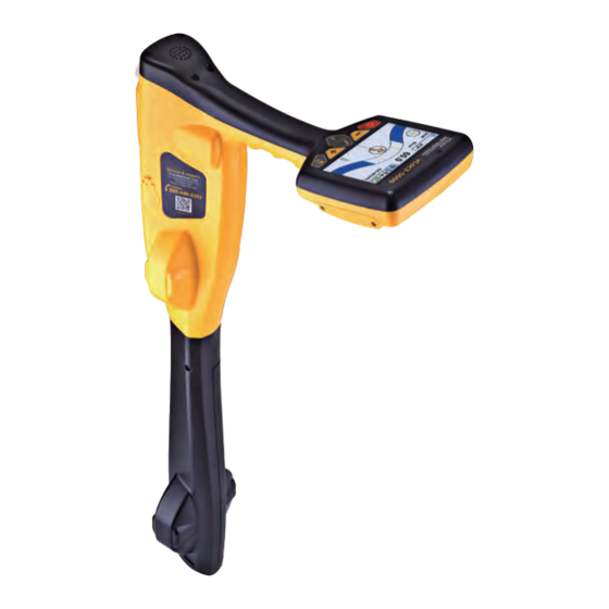
Receiver 3. vLoc3-5000 Receiver 3.1 vLoc3-5000 Receiver Overview The vLoc3-5000 is a Precision Location System designed to meet the needs of utility companies and their contractors. The following describes the features and use of the receiver: vLoc3-5000 receiver Alkaline battery holder... -
Page 12: Charging The Receiver Batteries
Bluetooth module 3.2 Charging the Receiver Batteries The vLoc3-5000 can be used with either alkaline batteries or an interchangeable rechargeable battery pack. The central illuminated section within the battery icon indicates the amount of charge remaining. ● Blue centre indicates Alkaline batteries. -
Page 13: Vloc3-5000 Receiver Keypad
3.4 User Menu The vLoc3-5000 has several features that can be switched on and off. These features are accessed through the user menu. Switch on the unit by pressing and holding the On/Off key until the start-up screen appears. The start-up screen can be configured to the user’s preference and is described later in the manual. -
Page 14: About
Self Test Main Menu Note that the manual shows three screens but only one is shown on the vLoc3-5000 display at a time. Note that where you see this sign it means that pressing the enter button gives access to the sub-menu associated with this button. -
Page 15: Frequency
Receiver 3.4.5 Frequency Use the enter key to enter the Frequency Sub-Menu. Scroll up and down the table using the “+” and “-” keys. The table contains all available frequency options. To simplify the operation of the unit, select only the frequencies applicable you your application. -
Page 16: Auto-Power Off
88.6 87.0 87.0 If the unit fails the test, try again in a more interference free area. If it continues to fail, return the unit to Vivax-Metrotech or one of its approved repair centers for investigation and repair. ™ Page 11 of 75... -
Page 17: Warnings
Receiver 3.6 Warnings Warnings are displayed in real time across the display as below: 94.6 43dB 0.00mA Power 50 3.6.1 Signal Overload This a very unusual situation and is usually caused by operating VERY close to a power transformer or placing the unit very close to a transmitter in the Induction mode. -
Page 18: Vloc3-5000 Receiver Locate Screen Shots
The user interface of the vLoc3-5000 is under continual development. The screen shots described may differ slightly from current screens. The vLoc3-5000 gives the user a choice of different locate screens. The choice of screen depends on application and user preference. - Page 19 Receiver The Classic Screen has all the functions normally seen on a classic cable locator. The main functions being: 60.0 4’0” 24dB 68mA SIS-491kHz Percentage signal strength (mirrors the bar graph setting) Gain setting Only visible with SiS frequencies, “+” indicates correct line, “ - ” indicates incorrect line...
-
Page 20: Classic Locating Modes (Response)
3.8 Classic Locating Modes (Response) The vLoc3-5000 receiver has an array of six antennas, and these can be toggled through different configurations (modes) to provide different responses to the signals radiating from buried utilities. The modes are: 3.8.1 Peak Response Mode... -
Page 21: Null Mode
Receiver 3.8.3 Null Mode This uses vertical antennas, and provides a minimum or “Null” response over the center of the buried line. The compass (line direction indicator) aligns itself parallel to the direction of the cable together with a line position indicator showing which side of the line the locator is (available in Active modes). -
Page 22: Information Pushbutton (Depth & Current)
SiS/SD section. Alternative locate screens As previously mentioned, the vLoc3-5000 has a number of alternative screens. The following section describes operation these screens. It is left to the user to decide which is the best screen for a particular application. - Page 23 Receiver Vector Screen The Vector Screen shows a cross sectional view through the ground. A plan view is also shown to help orientate the user over the line. The Vector Screen is particularly useful where access directly over the line is not possible. Depth and horizontal displacement distances are shown, even when not directly over the line.
- Page 24 Receiver The color of the confidence circle also changes depending on the degree of confidence: Green: - Low distortion/high confidence. Blue: - Minor distortion/medium confidence, proceed with care. Red: - Excessive distortion/low confidence, treat all data and measurements with caution.
- Page 25 Receiver 3. Position yourself so that the target line is pointing forward/back and is centralized on the screen. 0.18m 3.59mA 32.8kHz “Tram” lines either side of the line indicate an area of confidence. The closer the tram lines are together the greater the confidence.
- Page 26 Receiver Transverse-Plot Screen The Transverse-Plot screen is used to analyze the field shape at a particular location. This enables the user to get a better feel for the reliability of the data gathered. Two plots are generated simultaneously. ● Peak response ●...
-
Page 27: Using The Vloc3-5000
4.2.1 Detecting Power Signals 1. Switch on the vLoc3-5000 receiver and select Power mode using the “ f ” button. Notice that the antenna mode indicator will be showing “Peak” or “Omni-peak” as these are the only options in the passive modes. - Page 28 4. Keeping the vLoc3-5000 vertical, walk across the area to be checked keeping the orientation so that the blade is in line with the direction of walking (see diagram above) If using the Onmi-Peak mode, the orientation of the locator is not important.
-
Page 29: Detecting Radio Signals
Using the vLoc3-5000 7. Rotate the vLoc3-5000 on its axis to obtain the maximum signal. The vLoc3-5000 is now directly over the line and with the blade across the line. (if using the Omni-Peak mode there will be no change so switch to Peak mode if the direction is required). - Page 30 Using the vLoc3-5000 WARNING Only authorized personnel should make connections to cables. To make a direct connection, insert the direct connection connector to the transmitter. Insert the ground stake into the ground a few meters perpendicular to the line. Connect the black lead to the ground stake. Now take the red lead and connect to the target line.
-
Page 31: Signal Clamp (For Frequencies Above 8Khz)
Using the vLoc3-5000 4.3.2 Signal Clamp (for frequencies above 8kHz) In many situations, it is not possible to gain access to a cable to make an electrical contact. Or if there is, it is not safe to do so. The signal clamp provides an efficient and safe method of applying a locate signal to a cable. -
Page 32: Induction For Frequencies Above 8Khz
With no direct connection lead or signal clamp connected, the transmitter will automatically start to radiate a signal around the transmitter. These signals will penetrate the ground and couple onto buried lines. The signal will then travel along the line which can be detected with the vLoc3-5000 locator. Applying an induction signal to a line. -
Page 33: Locating Active Signals
It may be necessary to reduce the sensitivity to keep the bar graph on scale. This is normal and should be expected. Try to keep the vLoc3-5000 vertical and avoid swinging it as this may create false readings. -
Page 34: Searching (Sweeping) An Area In The Peak Mode
Using the vLoc3-5000 With the maximum signal found and the compass running Forward/Back, the vLoc3-5000 is now directly over the line and exactly across it. If the signal is not distorted, the position of maximum signal will coincide with the position as indicated by the line position indicator. -
Page 35: Tracing A Buried Line
If the depth measurement feature is activated, it is possible to take depth measurement estimations. To take a depth measurement, first pinpoint the position of the line as above (in section 4.7). Place the tip of the vLoc3-5000 on the ground making sure it is vertical and across the line i.e. -
Page 36: Distorted Fields
As seen previously, the vLoc3-5000 has the ability to detect the presence of possible distortion i.e. the Vector screen has a circle drawn around the target line which increases in size in the presence of possible distortion, and the Plan View screen has “Tram”... -
Page 37: Sonde-Location Mode
– a small peak with two “Nulls” between the peaks. The Sonde is located under the center of the “large peak”. The vLoc3-5000 detects the presence of the two “Null” signals and also the position of the main “Large Peak”. It uses this information to provide a reliable and efficient method of Sonde location. - Page 38 Using the vLoc3-5000 Hold the locator vertically and stationary with the tip on the ground. If the locator is within the range of the sonde the screen will appear similar to the one below with an arrow pointing in a particular and steady direction.
-
Page 39: Signal Select (Sis)
Using the vLoc3-5000 4.11 Signal Select (SiS) Signal Select is a system that helps confirm to the user that the correct line is being located and also conveys information relating to the quality of the signal being detected. Method: Apply the transmitter SiS tone using the Loc3-10SiSTx. Preferably use direct connection as this does not require transmitter –... -
Page 40: Signal Direction Precision Identification
4.12 Signal Direction Precision Identification Some models of vLoc3-5000 have a feature called “Signal Direction” . This feature is used to verify if the line being located is the target to which the transmitter has been connected. When a transmitter is connected to a target line, the signal travels along it and finds the easiest way to travel back, usually via the ground and ground stake. - Page 41 Using the vLoc3-5000 As a result, there can be multiple signals radiating from cables and pipes in the area making it difficult to identify the target line. These return signals are typically traveling in the opposite direction than the applied signal. The Signal Direction feature identifies which direction the signal is flowing and hence the target line.
- Page 42 Using the vLoc3-5000 79.1 27dB SD-EUR 44.8 27dB SD-EUR ● At some point, you may find that the SD arrow starts to flash – this is indicating that synchronization with the transmitter has deteriorated and a reset is required. 79.1...
-
Page 43: Data Logging
Data Logging 5. Data Logging The vLoc3-5000 has an internal memory that can be used to store locator data. Available storage size is four Gigabyte which relates to many thousands of records. The records are user initiated. These are records stored by the user whenever the “+” button is pressed when in the “Information”... -
Page 44: Bluetooth
Are you sure? 5.1 Bluetooth The vLoc3-5000 receiver can be fitted with a Bluetooth communications accessory. This allows communication with external GPS and or Dataloggers. The Bluetooth option can be retrofitted and can be ordered at a later date if preferred. -
Page 45: Pairing With External Gps/Dataloggers
● Switch on the external device. ● Switch on the vLoc3-5000 and enter the User Setup menu by a long press on the “ i ” button. ● Use the “+” and “ - ” keys to scroll down to the option “Bluetooth Pairing”. -
Page 46: Mylocator3
A “MyLocator3” icon will appear on the computer desktop. MyLocator3 Connect your vLoc3-5000 to your computer via the mini-USB connector which can be found under the battery cover flap. Launch MyLocator3 by double clicking on the icon. 5.3.2 My Locator3’s Basic Operation MyLocator3 operation, not requiring a USB security dongle. -
Page 47: Application Update
5.3.2.3 Locator Firmware Update Each time a locator is connected to the PC, its firmware version is checked against the latest version available on the Vivax- Metrotech server and the user is notified if an update is available as shown below. This feature will only be available if the computer is “online”. -
Page 48: Toolbar
5.3.3 Toolbar The vLoc3-5000 locator can be configured so that features can be switched on or off. This enables the user to tailor the instrument to meet the needs of their application while keeping the user interface uncluttered. The toolbar at the top of the screen enables the user to create configurations. -
Page 49: Splash Screen
The Download button can be used to set the splash screen immediately or the image can be sent to the locator along with the rest of the configuration by pressing the Write Configuration button. To remove a startup screen and revert to the default Vivax-Metrotech screen click on the “Clear” button and download the cleared screen. -
Page 50: Frequencies Page
Data Logging 5.3.6 Frequencies Page The “Frequencies” page will allow the user to refine which frequency modes are available when the locator F-key is pressed and which frequencies appear on the locator menu. ™ Page 45 of 75... -
Page 51: Menu Settings
Data Logging 5.3.7 Menu Settings The “Menu Settings” page allows the user control over which menu items appear on the locator and also the initial setting of the menu item when the locator is first used after configuration. The menu items with a right pointing arrow can be expanded to reveal further sub-menu items. -
Page 52: Advanced Features
5.3.8.1 Supervisor Lockouts This feature is available to anyone with a dongle (contact Vivax-Metrotech for the purchase of a dongle). When a dongle is connected to your computer via a standard USB socket, the icons for the “Splash Screen” page, “Frequencies” page and “Menu Settings”... -
Page 53: Loc3-10Sistx Transmitter
Loc3-10SiSTx Transmitter 6. Loc3-10SiSTx Transmitter 6.1 Loc3-10SiSTx Transmitter Overview The Loc3-10SiSTx transmitter is a rugged portable transmitter powered by alkaline “D” cells or Li-ion rechargeable batteries. The following describes the features and uses of the transmitter. Loc3-10SiS Transmitter 12 x D cell alkaline batteries Ground stake Alkaline battery tray Direct connection lead... -
Page 54: Pushbuttons
Loc3-10SiSTx Transmitter Mode Indication Icon Output Setting (Step) (filled box indicates current level has been reached, empty box indicates requested current level has not been achieved) High Voltage Warning* (output is enabled for high voltage) Digital Read Out (mA, volts, ohms) Frequency Being Transmitted Units (mA, volts, ohms) Loudspeaker Level... -
Page 55: Connections Block
In either case the charger is the same. Internal Charger Socket WARNING Only use a charger supplied by Vivax-Metrotech Corp. Using non-approved chargers may result in damage to the equipment or overheating/explosion. The battery condition (charge) is displayed on the left side of the display. -
Page 56: Removing The Battery Tray
WARNING Alkaline Batteries – insert alkaline batteries (x12) as shown: 6.2.3 Rechargeable Batteries ● Do not attempt to replace the rechargeable batteries or remove battery covers – return to Vivax-Metrotech or a Vivax- Metrotech approved service center for replacement. WARNING Only use a Vivax-Metrotech recommended charger. -
Page 57: Rechargeable Battery Pack Charging And Disposal
Loc3-10SiSTx Transmitter 6.2.5 Rechargeable Battery Pack Charging and Disposal Follow instructions detailed in the “General Safety & Care” Information section of this document. Only use the battery charger supplied. Using an unapproved charger may damage the battery pack and could cause overheating. -
Page 58: Clamp Mode
6.3.3 Clamp Mode Plugging the signal clamp supplied by Vivax-Metrotech into the output socket will place the transmitter in “Clamp” mode. An icon confirming this is displayed on the display. The icon flashes when the transmitter is transmitting. When using the clamp no ground connection is needed. -
Page 59: Frequencies
Loc3-10SiSTx Transmitter 6.4 Frequencies 6.4.1 Frequencies and Power Output The Loc3-10SiSTx transmitter is supplied with a predefined set of transmit frequencies. The most commonly used frequencies will be preset by the factory. Additional frequencies are available to be selected in the frequencies list see section 6.4.2. Example of standard frequencies pre-set at the factory are: ●... -
Page 60: Most Used Frequencies (Frequency Selection) Feature
Loc3-10SiSTx Transmitter 6.4.2 Most Used Frequencies (Frequency Selection) Feature This feature can be used to allow the operator to choose the most used frequencies from a list of possible frequencies. Once these frequencies are selected in the main menu, by pressing the “ f ” pushbutton, the user can scroll through them. At any time the user can add or remove frequencies from the above list, by following the below procedure. -
Page 61: Multi-Frequency Mode For Direct Connection
Loc3-10SiSTx Transmitter 2. Screen will show a list of frequencies available, with the central one in a box. Frequency Menu SD-USA FF Low FF High 3. Pressing the “+” or “ - ” pushbuttons, you can scroll up or down through the available frequencies. 4. -
Page 62: Remote The Operation Of Transmitter
The Loc3-10SiSTx can be remotely operated from the receiver. This is an optional feature and requires the transmitter radio link option to be installed in both the vLoc3-5000 and Loc3-10SiSTx. This feature is only available on the Loc3-10SiSTx and is a factory fit option so must be requested at the time of ordering. - Page 63 83.1 kHz While the icon on the transmitter is flashing, indicating that it is waiting to connect to a receiver, switch on the vLoc3-5000 receiver and enter the user menu by pressing and holding the information button. Scroll down the menu options until “Transmitter Link”...
- Page 64 Loc3-10SiSTx Transmitter Transmitter Link Menu Imp/Metric Meter Transmitter Link Disabled Continuous info. GPS source Internal Bluetooth Pairing Transmitter Link Transmitter Control Select the “Transmitter Link”. Check that the radio module is enabled. If not, press the return button to enable the Transmitter Link.
- Page 65 Loc3-10SiSTx Transmitter Also shown is the: Radio link signal strength, in this case 40%. Output mode, in this case direct connection. Output current, in this case 100mA. Beeper volume setting, in this case level 2. Transmitter battery level. Use the Information button to navigate/exit back to the locate screen. When in the Locate screen the status of the link is displayed in the status bar.
-
Page 66: Using Accessories
In the case of cables, faults are usually caused by insulation damage allowing the metallic sheath (or internal conductor) to become in contact with the ground. It is intended to be used with the vLoc3-5000 range of locators and will require a fault find signal applied to the faulty conductor from a Vivax-Metrotech compatible transmitter. - Page 67 Using Accessories To detect a damaged section, the line should be isolated and have all ground bonding removed. This will ensure that the ground fault is not masked by deliberate bonding to ground. The A-frame cannot distinguish between these two situations. After isolating the line, use the transmitter resistance measuring function, or a dedicated resistance measuring device to confirm that there is a fault to ground.
- Page 68 Using Accessories 26 dB 20 dB 8KFF 8KFF (Note that the A-frame is not shown connected to the receiver so as to simplify the diagram). Eventually, the A-frame will detect the fault signal and the “Fault Find” arrow will point forward. Continue moving forward, it may be worth reducing the distance between measurements points as the fault is neared.
-
Page 69: Using The Vloc3-5000 Sis Remote Antenna
Are you sure? Deleting logs..7.3 Using the vLoc3-5000 SiS Remote Antenna The remote stethoscope antenna can be used to help trace a particular cable on a cable tray or where cables are bunched together. - Page 70 120dB 65.5kHz Ensure the frequency selected on the vLoc3-5000 is the same as selected on the transmitter. Place the stethoscope on each of the suspected target cables, if possible part each one from the bunch before each test, with the flats of the antenna in line with the route of the cable.
-
Page 71: Using The Sis Signal With The Remote Antenna To Help Identify A Cable
Using Accessories WARNING The remote stethoscope antenna is a useful tool to help trace cables. However, it should not be used as positive identification before an unused cable is cut. Always follow company procedures when cutting disused or isolated cables. The remote stethoscope antenna can be used to help identify disused and isolated cables. - Page 72 Using Accessories Method: 1. Apply the signal using the direct connection method. Remember to isolate the cable beforehand as below. It is also preferable to use the ground stake as an independent ground. Using the station ground may result in multiple signals as the signal will return along commonly bonded cables.
- Page 73 Using Accessories Now press the “Return” key. The screen should now show something similar to the below with the “+” icon showing and little or no red shown in the distortion indicator. 52.1 25dB SiS8440 The system is now ready to identify the cable at the location of interest. Identifying a cable Having confirmed the antenna is synchronized with the receiver, proceed to the location the cable is to be identified.
-
Page 74: Signal Select Clamp
Signal Select Clamp Mode Plugging the Signal Select Clamp supplied by Vivax-Metrotech into the output socket will place the transmitter in “Signal Select Clamp” mode. An icon confirming this is displayed on the display. The icon flashes when the transmitter is transmitting. When using the clamp, no ground connection is needed. - Page 75 4.11 “Synchronizing” Used in conjunction with the vLoc3-5000 receiver, the Signal Select feature becomes a powerful tool in aiding accurate cable identification. At the receiver, a positive (+) icon appears on the operational interface if the operator correctly identifies and traces the line.
-
Page 76: Accessories & Options
Accessories & Options 8. Accessories & Options 8.1 A-frame The A-frame accessory is used to detect ground faults on pipes and cables. In the case of pipes, the faults consist of coating defects. In the case of cables, faults are usually caused by insulation damage allowing the metallic sheath (or internal conductor) to become in contact with the ground. -
Page 77: Receiver Vehicle Charging Lead
Accessories & Options 8.6 Receiver Vehicle Charging Lead 12ft (4m) long lead to charge the receiver’s battery (Lithium-ion) while on the move. It is preferable to connect the charger to a cigarette lighter socket that is permanently live. However, do not leave connected to the receiver for excessively long periods. 8.7 Sondes D18-33-SR44 Sonde ●... -
Page 78: Clamps
Accessories & Options 8.8 Clamps An accessory used to apply the transmitter signal to an insulated line, removing the need to connect the transmitter signal directly to a conductor or cable sheath. ● Available in 2-inch (50mm), 4-inch (100mm) and 5-inch sizes. ●... -
Page 79: Loc3 Series Charger
Accessories & Options 8.12 Loc3 Series Charger Mains charger (100-250V AC input) used to charge 10 Watt rechargeable battery packs. Supplied as standard with rechargeable battery option. 8.13 Loc3 Series Rechargeable Battery Tray The Li-ion rechargeable battery pack consist of the battery and charger. 8.14 Live Plug Connector (LCC) For use on live cables up to 480V AC 60/50Hz. - Page 80 Illustrations used in the preparation of this manual will inevitably show some resemblance to similar illustrations from other Manufacturers-some manufacturers have given permission for the use of their graphics (Vivax-Metrotech & Seba) is given credit for these use. This statement is intended to attribute such credit.
- Page 81 Notes: Locators & Supplies, Inc. (800) 950-6666 sales@locatorsandsupplies.com www.locatorsandsupplies.com Vivax-Metrotech Corporation 3251 Olcott Street, Santa Clara, CA 95054, USA Website: www.vivax-metrotech.com...
Need help?
Do you have a question about the vLoc3-5000 and is the answer not in the manual?
Questions and answers