Table of Contents
Advertisement
E2 Adjustable Speed Driver
TAIAN
High Performance Adjustable Speed Micro Drives
E2 Series
110V
220V
440V
Microprocessor Controlled
IGBT Drive
Inverter Motor Speed Regulator
Operating Manual
0.2~0.75KW
( 0.53~1.6KVA )
0.2~2.2KW
( 0.53~4.0KVA )
0.75~2.2KW
( 1.7~4.0KVA )
Advertisement
Table of Contents

Summary of Contents for T-Verter E2 Series
- Page 1 E2 Adjustable Speed Driver Microprocessor Controlled IGBT Drive Inverter Motor Speed Regulator Operating Manual TAIAN High Performance Adjustable Speed Micro Drives E2 Series 110V 0.2~0.75KW ( 0.53~1.6KVA ) 220V 0.2~2.2KW ( 0.53~4.0KVA ) 440V 0.75~2.2KW ( 1.7~4.0KVA )
-
Page 2: Table Of Contents
Operations Manual Table of Contents Foreword ..................1 Chapter 1 Safety Precautions 1. Precautions for Operation ........3 2. Environmental Precautions ........6 Chapter 2 Hardware Instruction and Installation 1. Operational Environment.........7 2. Sample Model No. Identification......8 3. Specifications ............9 4. Wiring ..............15 5. -
Page 3: Foreword
1. Foreword To fully employ all functions of this AC Drive, and to ensure the safety for its users, please read through this operations manual in detail. Should you have any further questions, please feel free to contact your local distributor or regional representative. ※Please use Precaution with this product The AC Drive is a power electronic device. - Page 4 2. Examination before installation Every inverter has been fully tested and examined before shipment. Please carry out the following examination procedures after unpacking your AC inverter. Check to see if the model number of the AC inverter matches the model number of the AC inverter that you ordered.
- Page 5 Chapter 1: Safety Precaution 1. Precautions for operation Before turning ON power CAUTION Choose the appropriate power source with correct voltage settings for the input voltage specification of the AC inverter. WARNING Special care must be taken while wiring the primary circuitry panel. The L1 and L2 terminal must be connected to the input power source and must not be mistakenly connected to T1, T2 or T3 out put terminals.
- Page 6 When power is applied WARNING Do not attempt to install or remove input or out put connectors of inverter when the power supply is turned on. Otherwise, the inverter may be damaged due to the surge peak caused by the insertion or removal of power. When momentary power loss is longer than 2 seconds (the large of horse power, the longer of time), the inverter does not have enough storage power to control the circuit;...
- Page 7 Under Operation WARNING Do not use a separate device to switch ON or OFF motor during operation. Otherwise, the inverter may experience an over-current breakdown. WARNING Do not remove the front cover of the inverter when the power is ON to avoid personnel injury caused by electrical shock.
- Page 8 2. Precautions of operation environment Avoid any direct sunlight Keep away from Keep away from oil corrosive gas or liquid grease and gas Keep away from rain or Avoid metal dust and Keep away from salty where dripping water may dusty environments environments get into the inverter...
-
Page 9: Chapter 2 Hardware Instruction And Installation 1. Operational Environment
Chapter 2: Hardware Instructions and Installation 1. Operational Environment The installation site of the inverter is very important. It relates directly to the functionality and the life span of your inverter. Please carefully choose the installation site to meet the following requirements: Mount the unit vertically Environment temperature: -10... -
Page 10: Sample Model No. Identification
Ventilation & Installation Direction Front View Note: Maximum temperature in the enclosure 50 ℃ 2. Sample Model No. Identification ⇓ Inverter Model MODEL: E2-201-M1F ⇓ Input Power Rating I/P: AC 1PH 200 ~ 240V 50/60 Hz ⇓ Output Rating O/P: AC 3PH 0 ~ 240V 1 Hp 4.2 Amps E2 - Series Power... -
Page 11: Specifications
3.Specification: Basic specification: Model : E2- 1P5-H1x 1P2-H1x Suitable Motor Power Rating (KW) 0.75 Motor (HP) Output Current (A) Rated Capacity (KVA) 0.53 0.88 Weight (Kg ) 0.72 Input Voltage Max. Single phase 100-120V (+10%, -15%), 50 / 60Hz (+/-5%) Output Voltage Max. - Page 12 Functional specification: Item Specification Input Signal Type PNP type (SOURCE) input (External 24VDC Input is allowed) Control Method Sinusoidal wave PWM control Freq. Range 1~200 Hz*1 Resolution Setting Digital: 0.1 Hz (1 ~ 99.9 Hz); 1 Hz (100 ~ 200 Hz) Freq.
- Page 13 Suitable optional and Wiring Specification Molded-Case Circuit Breaker / Magnetic Contact Warrantee does not apply to damage caused by the following situations: (1) Damage to the inverter caused by the lack of appropriate molded-case circuit breaker or when a circuit breaker with too large of capacity is installed between the power supply and the inverter.
- Page 14 Application and precautions of Peripherals From the Power Source: Apply the power source at the correct rated voltage to prevent from damaging the inverter. A Power Disconnect or Circuit breaker must be installed between the AC power supply and the inverter.
- Page 15 External wiring should be carried out in accordance with following requirement. Check and reassure the wiring is correct after the wiring is complete. (Do not utilize the control circuitry buzzer to check the wiring.) EMI connections: It is very important that the connections between the inverter, the shielded motor cable, and the EMI filters are tested as follows.
- Page 16 Class A: Drive When the distance between the inverter and motor is longer than 100 meters, cable wire should be carefully chosen to reduce the wiring resistance below 3% and the voltage drop (V) = √3 x Wire resistance (Ω/km) x wire length (m) x current x 10 Control circuitry wiring must be separated terminated and away from the primary power circuitry and other high-voltage or large-current power lines to avoid noise interference.
-
Page 17: Wiring
loads (such as soldering machines or large current motors). They should be grounded separately. Grounding circuitry must not be formed when grounding several inverters together. (a) good (b) good (c) not good (D) Wire specification, apply appropriate wire with correct diameter for primary power circuitry and control circuitry in accordance with electricity regulations. - Page 18 type ring terminals. Note: Only for 202/203/401/402/403. (External 24V supply) –...
- Page 19 Inverter terminal descriptions Primary Circuitry Terminal Block (TM1) descriptions Terminal Symbol Function Description L1/L (R) Primary power source input to Drive L2 (S) Single phase: L1/L2 or L/N L3/N (T) Three phase: L1/L2/L3 Extermal braking resistor terminal (Only for E2-202/203/401/402/403) T1 (U) Inverter output to Motor T2 (V)
-
Page 20: Dimensions & Location Of Terminal Block
SW1 function description SWITCH 1 External signal type 0~20mA analog signal (When F_11 is set to 1) 4~20mA analog signal (When F_11 is set to 2) 0~10 VDC analog signal (When F_11 is set to 1) Dimensions & Location of terminal block E2-1P2/1P5/101/2P2/2P5/201: See NOTE Unit: mm... - Page 21 E2-202/203/401/402/403: See NOTE of Page 18 U ni t : m m LEN G TH M O D EL 143. 1127. 5 8. 0 E2-202/ 203/ 401/ 402/ 403 LEN G TH M O D EL 171. 7 E2-202/ 203/ 401/ 402/ 403 Dimensions &...
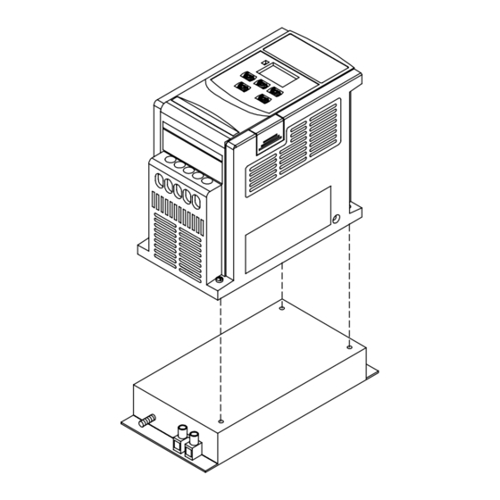
- Page 22 Inverter with class B filter mounted. Inverter with class B filter & Din rail mounted kit. Mounting Instructions...
- Page 23 Din Rail Mounting Diagram Step1- Aim and insert the 4 retention ribs of the Step1- DIN Rail at the 4 Use a small holes in rear panel Inserting hole screwdriver of inverter inserting it into the middle rib middle rib of DIN Step2- Rail and press the Push the DIN Rail...
- Page 24 E2-2P2/2P5/201- N4X (IP65)TYPE: DATA RESET STOP 117.23 133.57 133.00 UNIT : mm...
- Page 25 E2-202/203/401/402/403- -N4X (IP65)TYPE: UNIT : mm...
- Page 26 E2-2P2/2P5/201- - N4X(IP65)TYPE INSTALLATION : P o ten tio m eter R E V -0 -F W D D A T A R E S E T E N T S W IT C H R U N D S P F U N S T O P P O W E R...
- Page 27 E2-2P2/2P5/201- -N4 (WITHOUT SWITCH TYPE ) CONNECTIONS & EMC MOUNTING: CONNECTIONS 4 x Outer cover screw EMC MOUNTIING 200mm Cutting Length of cable shield Power supply Power cable supply L1,L2, cable Motor cable ,T1,T2,T3 Motor cable TM1 terminals Length: Max 2M Note: TM2 Remote control Cable shielding...
- Page 28 E2-2P2/2P5/201- -N4S (WITH SWITCH TYPE ) EMC MOUNTING & CONNECTIONS : CONNECTIONS 4 x Outer cover screw Power supply cable L1,L2, Motor cable ,T1,T2,T3 Power supply cable Motor cable Plug-in terminals EMC MOUNTIING 200mm Cutting Length of cable shield Power supply cable L1,L2, Motor cable...
- Page 29 Chapter 3 Software Index Keypad operating instructions Keypad Description POWER LED DATA ▼ ▲ RESET STOP CAUTION Do not operate keypad by screwdriver or other sharp-ended tool to avoid damaging keypad. Brief keypad operation flowchart ▲ ▼ (FREQ) * 1 (FREQ) (READ) ▲...
-
Page 30: Parameters List
Parameter List Factory Function Function Description Page Note Unit Range setting Factory Adjustment Accel. Time Accel. time 0.1Sec 0.1 ~ 999 S *1 *3 Decel. Time Decel. time 0.1Sec 0.1 ~ 999 S *1 *3 0: Forward / Stop, Reverse / Stop Operation mode 0 ~ 1 1:Run/Stop, Forward / Reverse... -
Page 31: Parameter Function Description
Factory Page Note Function Description Unit Range Function setting 0: REV run Reverse Lock-Out 0 ~ 1 1: REV run Lock-Out 0: enabled Momentary power 0 ~ 1 loss 1: disabled Auto restart Number of Auto-restart times 0 ~ 5 010: Constants initialization to 50Hz system Factory setting 020: Constants initialization to 60Hz system... - Page 32 F_03: Operation mode selection = 0: Forward / Stop, Reverse / Stop 1: Run / Stop, Forward / Reverse NOTE 1: F_03 takes effect only when F_10 = 1 (external operation control) F_03 = 0 3 FWD /Stop 3 Run / Stop F_03 = 1 control 4 REV /Stop...
- Page 33 F_05: V/F pattern setting = 1 ~ 6 Selecting F_05 = 1-6 to select one of the six preset V/F patterns. (Refer to the following tables) Specification 50 Hz System Application General Application High starting torque Decreasing torque V (%) V (%) V (%) V/F pattern...
- Page 34 F_06: frequency upper limit range=1~120Hz F_07: frequency lower limit range=1~120Hz (1~200Hz with CPU versionv1.9 and above) F_06: Factory setting refers to F_25. Internal frequency F_06 (freq. Upper limit) signal F_07 (freq. Lower limit) (NOTE) Frequency setting signal NOTE: If F_07 = 0 Hz, The frequency instruction is equal to 0Hz, the inverter will stop at 0 speed.
- Page 35 F_11: Speed Control = 0: Keypad = 1: Analog Speed Pot Terminal (TM2) (0 ~ 10V / 0-20mA) = 2: Analog Speed Pot Terminal (TM2) ( 4-20mA ) NOTE 1: When jog frequency or Sp1 frequency is F_06 switched on, the frequency is setup by Sp1 speed, the ▲▼...
- Page 36 Voltage 100% F_13= 50/60 2.5/3.0 NOTE: When F_13 = 0, the torque boost function is disabled. F_14 Stopping method = 0 : Controlled deceleration stop = 1 : free run to stop F_15 DC braking time = 0 ~ 25.5 sec F_16 DC braking starting frequency = 1 ~ 10 Hz F_17 DC braking level = 0 ~ 20 %...
- Page 37 F_18: Motor rated current = 50~100 %(0~200%: CPU version v1.9 and above) 1. The electronic thermal overload protection for motor: (1) Motor rated current = Inverter rated current x F_18 F_18 = Motor rated current / inverter rated current (2) When the load is within 100% of the motors rated current, the operation continues. When the load reaches 150% of the motors rated current the operation is allowed to continue for 1 minute.
- Page 38 F_19: Multifunctional input terminal 1 function = 1~ 5(1~6:CPU version v1.9 and above) F_20: Multifunctional input terminal 2 function = 1~ 5(1~6:CPU version v1.9 and above) F_19=1 or F_20 =1: JOG control (refer to F_09) F_19, F_20 =2 or 6 Multi-speed control: F_19=2 &...
- Page 39 Time Run/Stop F_20=4 5. F_19, F_20 = 5: Auto Reset when inverter faults. F_21: Multi-function output terminal control = 1 ~ 3 1. F_21 = 1: Run mode signal 2. F_22 = 2: At Frequency Speed Signal 3. F_21 = 3: Fault signal Terminal1 and2 of TM2 are activated at CPF, OL1, OL2, OCS, OCA, OCC, Ocd , Ocb , OVC , LVC , OHC.
- Page 40 F_23: Auto-restart after momentary power loss =0: auto-restart enabled =1: auto-restart disabled 1. When the AC power supply is temporary below low voltage protection levels because of power company issues or encountering large current loading in the same power supply system, the inverter will stop its output immediately.
- Page 41 4. If either of following situations should develop, the auto restart times will be reset: No additional malfunction (in operation or stop) occurs within 10 minutes. Press RESET button. F_25: Return to Factory Pre-Settings = 010: Constants initialization to 50Hz system = 020: Constants initialization to 60Hz system 1.
- Page 42 F_29: CPU program version F_30: Last three faults 1. Last three faults: indicate the sequence of the occurrence of malfunctions by the location of decimal point. x.xx indicates a recently happened malfunction. xx.x indicates the last malfunction that happened. xxx. Indicates the earliest malfunction in the record. 2.
-
Page 43: Malfunction Indication And Countermeasure
Malfunction Indications and Countermeasures 1. Manual reset inoperative malfunctions INDICATION CONTENT POSSIBLE CAUSE COUNTERMEASURE Place a RC surge absorber in Program error Outside noise interference parallel with the noise generating magnetic contact EEPROM error EEPROM defective Replace EEPROM Voltage too 1. - Page 44 3.Manual Reset and Auto-Reset Operative Malfunction INDICATION CONTENT POSSIBLE CAUSE COUNTERMEASURE Transient 1. Motor coil short-circuit with 1. Examining motor over-current external casing 2. Examining wiring starting machine 2. Motor connection wire 3. Replace transistor module short-circuit with grounding 3. Transistor module damaged Over-current at 1.
- Page 45 Special Condition Description INDICATION CONTENT DESCRIPTION When F_11 = 0, F_7= 0 and frequency setting < 1 Hz Zero Speed When F_11 = 1, F_7<(F_6/100), and frequency setting Stopping <(F_6/100) 1. If the inverter is set to external operation (F_10 = 1) and direct start is disabled (F_28 =1), the inverter cannot be Fail to start started and will flash SP1 when operation switch turned to...
-
Page 46: General Malfunction Examination Method
General Malfunction Examination Method ABNORMALITY CHECK POINT COUNTERMEASURE Check if the power source on. Is the power source voltage delivered to Turn power source OFF and then ON L1, L2 terminal (is the charging indicator again. illuminated)? Reconfirm the power voltage level. Is there voltage output from output Turn power source OFF and then ON Motor... - Page 47 Chapter 4: Troubleshooting Procedures Inverter Malfunction Clearly defined m alfunction Exam ining com ponent with Sign of burn Any sign of burnt sign of burnt or breakage or breakage of breakage? Indication of ABNORMAL Is the prim ary Replace DM abnorm ality circuitry DM norm al? Proceed exam ination...
- Page 48 ( Continued ) Examining Inverter parameters Carry out parameter initialization Designate operation control method Frequency instruction setting Does the controller displays Replace control board frequency setting? Is there voltage output on Replace control board UVW terminals? No, The problem Is replacing is not corrected Connect to motor and control board correct...
- Page 49 Error handling of malfunction indication of OC.OL When inverter display malfunction indication OC.OL. Is the primary ABNORMAL Replace I.G.B.T. circuit I.G.B.T. normal? NORMAL Is the appearance Replace defective PCB normal? Switch ON power supply Is there any malfunction indication Is the current ABNORMAL Input operation detector normal?
- Page 50 Error handling of malfunction indication of OV.LV Inverter display OV.LV Is there any abnormal breakage Replace defective board on appearance Switch ON power supply Is there any Replace control board malfunction indication Input operation instruction Input frequency instruction Is the output Replace control board frequency of controller displayed...
- Page 51 (1). Motor inoperative Is the circui t breaker (MCCB) switched ON? Can not Wiring short-circuit Can you switch ON the MCCB? Is the • Power source voltage between ABNORMAL abnormality L1-L2 power input terminals normal? • Poor wiring Normal (within +/- 10% of nominal value) E2 malfunction Is Power LED off ? Place the operation...
- Page 52 (2). Motor over-heat Reduce loading there over-loading Enlarge E2 and condition or the load current exceeds rated Motor capacity current? Operate at low Select another motor speed for a long time? Is the voltage level between E2 malfunction T1-T2, T2-T3, and T3-T1 normal? Is there anything that might...
- Page 53 (3). Disturbing motor operation Is the Increase or decrease appropriate acceleration/ During acceleration or acceleration / deceleration time setting deceleration ? deceleration time appropriate? Appropriate Reduce load Increase E2 and motor capacity Is the voltage level E2 malfunction between T1-T2, T2-T3, and T3-T1 normal? YES (The differences between different wires are within ±...
- Page 54 Routine examination and periodical examination Inverter requires routine and periodical examination and maintenance Carry out the examination only after the “ Power LED ” indicator goes off for at least 5 minutes Examination Maintenance Maintenance period Examination Criterion Countermeasure item description method Routine...
- Page 55 (a) Remove all conducting wires between Drive and outside world. Power must be turned OFF. (b) The dielectric strength test inside Drive should be carried out only for T-VERTER major circuitry. Use DC 500V: high resistance meter. Measured resistance should be higher than 100M ohm.
- Page 56 Voltage Current Measurement The voltage and current measurement on the primary and secondary side of the inverter may be different due to instrumentation variations. Refer to following diagram for measurement: Signal-phase power supply To motor Different kinds of instrument NOTE Measurement Measuring point Instrument...
- Page 57 EMI Filter (class B) Specification Model Dimension (mm) Current (A) Inverter model E2-2P2-M1F/E2-2P2 -H1F E2-2P5-M1F/E2-2P5 E2F-2102 156 X 76 X 25 -H1F E2-201-M1F/E2-201- E2-202-H1F E2F-2202 172 X 120.2 X 11 E2-203-H1F E2-401-H3F E2F-4103 172 X 120.2 X 11 E2-402-H3F E2-403-H3F DIN RAIL Specification Dimension Model...
- Page 58 Note 1: Without transistor and resister built-in. Specification of Braking Resister Specification Torque Size of Weight Model of Rate of Braking Size of of Braking Model of carton (5pc) Braking Motor Resister resister Resister Inverter braking (L*W*H) (L*W*H) mm resister (KW) ED(%) (Ω)
- Page 59 PARAMETERS TABLE CUSTOMER MODEL APPLICATION TELEPHONE ADDRESS F_## Value Setting F_## Value Setting F_## Value Setting F_00 F_11 F_22 F_01 F_12 F_23 F_02 F_13 F_24 F_03 F_14 F_25 F_04 F_15 F_26 F_05 F_16 F_27 F_06 F_17 F_28 F_07 F_18 F_29 F_08 F_19 F_30...
- Page 60 3.Specification: Basic specification: Model : E2- 1P5-H1x 1P2-H1x Suitable Motor Power Rating (KW) 0.75 Motor (HP) Output Current (A) Rated Capacity (KVA) 0.53 0.88 Weight (Kg ) 0.72 Input Voltage Max. Single phase 100-120V (+10%, -15%), 50 / 60Hz (+/-5%) Output Voltage Max.
- Page 61 E2 Adjustable Speed Driver Microprocessor Controlled IGBT Drive Inverter Motor Speed Regulator Operating Manual TAIAN High Performance Adjustable Speed Micro Drives E2 Series 110V 0.2~0.75KW ( 0.53~1.6KVA ) 220V 0.2~2.2KW ( 0.53~4.0KVA ) 440V 0.75~2.2KW ( 1.7~4.0KVA )
-
Page 62: Environmental Precautions
Operations Manual Table of Contents Foreword ..................1 Chapter 1 Safety Precautions 1. Precautions for Operation ........3 2. Environmental Precautions ........6 Chapter 2 Hardware Instruction and Installation 1. Operational Environment.........7 2. Sample Model No. Identification......8 3. Specifications ............9 4. Wiring ..............15 5. - Page 63 1. Foreword To fully employ all functions of this AC Drive, and to ensure the safety for its users, please read through this operations manual in detail. Should you have any further questions, please feel free to contact your local distributor or regional representative. ※Please use Precaution with this product The AC Drive is a power electronic device.
- Page 64 2. Examination before installation Every inverter has been fully tested and examined before shipment. Please carry out the following examination procedures after unpacking your AC inverter. Check to see if the model number of the AC inverter matches the model number of the AC inverter that you ordered.
- Page 65 Chapter 1: Safety Precaution 1. Precautions for operation Before turning ON power CAUTION Choose the appropriate power source with correct voltage settings for the input voltage specification of the AC inverter. WARNING Special care must be taken while wiring the primary circuitry panel. The L1 and L2 terminal must be connected to the input power source and must not be mistakenly connected to T1, T2 or T3 out put terminals.
- Page 66 When power is applied WARNING Do not attempt to install or remove input or out put connectors of inverter when the power supply is turned on. Otherwise, the inverter may be damaged due to the surge peak caused by the insertion or removal of power. When momentary power loss is longer than 2 seconds (the large of horse power, the longer of time), the inverter does not have enough storage power to control the circuit;...
- Page 67 Under Operation WARNING Do not use a separate device to switch ON or OFF motor during operation. Otherwise, the inverter may experience an over-current breakdown. WARNING Do not remove the front cover of the inverter when the power is ON to avoid personnel injury caused by electrical shock.
- Page 68 2. Precautions of operation environment Avoid any direct sunlight Keep away from Keep away from oil corrosive gas or liquid grease and gas Keep away from rain or Avoid metal dust and Keep away from salty where dripping water may dusty environments environments get into the inverter...
- Page 69 Chapter 2: Hardware Instructions and Installation 1. Operational Environment The installation site of the inverter is very important. It relates directly to the functionality and the life span of your inverter. Please carefully choose the installation site to meet the following requirements: Mount the unit vertically Environment temperature: -10...
- Page 70 Ventilation & Installation Direction Front View Note: Maximum temperature in the enclosure 50 ℃ 2. Sample Model No. Identification ⇓ Inverter Model MODEL: E2-201-M1F ⇓ Input Power Rating I/P: AC 1PH 200 ~ 240V 50/60 Hz ⇓ Output Rating O/P: AC 3PH 0 ~ 240V 1 Hp 4.2 Amps E2 - Series Power...
- Page 71 3.Specification: Basic specification: Model : E2- 1P5-H1x 1P2-H1x Suitable Motor Power Rating (KW) 0.75 Motor (HP) Output Current (A) Rated Capacity (KVA) 0.53 0.88 Weight (Kg ) 0.72 Input Voltage Max. Single phase 100-120V (+10%, -15%), 50 / 60Hz (+/-5%) Output Voltage Max.
- Page 72 Functional specification: Item Specification Input Signal Type PNP type (SOURCE) input (External 24VDC Input is allowed) Control Method Sinusoidal wave PWM control Freq. Range 1~200 Hz*1 Resolution Setting Digital: 0.1 Hz (1 ~ 99.9 Hz); 1 Hz (100 ~ 200 Hz) Freq.
- Page 73 Suitable optional and Wiring Specification Molded-Case Circuit Breaker / Magnetic Contact Warrantee does not apply to damage caused by the following situations: (1) Damage to the inverter caused by the lack of appropriate molded-case circuit breaker or when a circuit breaker with too large of capacity is installed between the power supply and the inverter.
- Page 74 Application and precautions of Peripherals From the Power Source: Apply the power source at the correct rated voltage to prevent from damaging the inverter. A Power Disconnect or Circuit breaker must be installed between the AC power supply and the inverter.
- Page 75 External wiring should be carried out in accordance with following requirement. Check and reassure the wiring is correct after the wiring is complete. (Do not utilize the control circuitry buzzer to check the wiring.) EMI connections: It is very important that the connections between the inverter, the shielded motor cable, and the EMI filters are tested as follows.
- Page 76 Class A: Drive When the distance between the inverter and motor is longer than 100 meters, cable wire should be carefully chosen to reduce the wiring resistance below 3% and the voltage drop (V) = √3 x Wire resistance (Ω/km) x wire length (m) x current x 10 Control circuitry wiring must be separated terminated and away from the primary power circuitry and other high-voltage or large-current power lines to avoid noise interference.
- Page 77 loads (such as soldering machines or large current motors). They should be grounded separately. Grounding circuitry must not be formed when grounding several inverters together. (a) good (b) good (c) not good (D) Wire specification, apply appropriate wire with correct diameter for primary power circuitry and control circuitry in accordance with electricity regulations.
- Page 78 type ring terminals. Note: Only for 202/203/401/402/403. (External 24V supply) –...
- Page 79 Inverter terminal descriptions Primary Circuitry Terminal Block (TM1) descriptions Terminal Symbol Function Description L1/L (R) Primary power source input to Drive L2 (S) Single phase: L1/L2 or L/N L3/N (T) Three phase: L1/L2/L3 Extermal braking resistor terminal (Only for E2-202/203/401/402/403) T1 (U) Inverter output to Motor T2 (V)
- Page 80 SW1 function description SWITCH 1 External signal type 0~20mA analog signal (When F_11 is set to 1) 4~20mA analog signal (When F_11 is set to 2) 0~10 VDC analog signal (When F_11 is set to 1) Dimensions & Location of terminal block E2-1P2/1P5/101/2P2/2P5/201: See NOTE Unit: mm...
- Page 81 E2-202/203/401/402/403: See NOTE of Page 18 U ni t : m m LEN G TH M O D EL 143. 1127. 5 8. 0 E2-202/ 203/ 401/ 402/ 403 LEN G TH M O D EL 171. 7 E2-202/ 203/ 401/ 402/ 403 Dimensions &...
- Page 82 Inverter with class B filter mounted. Inverter with class B filter & Din rail mounted kit. Mounting Instructions...
- Page 83 Din Rail Mounting Diagram Step1- Aim and insert the 4 retention ribs of the Step1- DIN Rail at the 4 Use a small holes in rear panel Inserting hole screwdriver of inverter inserting it into the middle rib middle rib of DIN Step2- Rail and press the Push the DIN Rail...
- Page 84 E2-2P2/2P5/201- N4X (IP65)TYPE: DATA RESET STOP 117.23 133.57 133.00 UNIT : mm...
- Page 85 E2-202/203/401/402/403- -N4X (IP65)TYPE: UNIT : mm...
- Page 86 E2-2P2/2P5/201- - N4X(IP65)TYPE INSTALLATION : P o ten tio m eter R E V -0 -F W D D A T A R E S E T E N T S W IT C H R U N D S P F U N S T O P P O W E R...
- Page 87 E2-2P2/2P5/201- -N4 (WITHOUT SWITCH TYPE ) CONNECTIONS & EMC MOUNTING: CONNECTIONS 4 x Outer cover screw EMC MOUNTIING 200mm Cutting Length of cable shield Power supply Power cable supply L1,L2, cable Motor cable ,T1,T2,T3 Motor cable TM1 terminals Length: Max 2M Note: TM2 Remote control Cable shielding...
- Page 88 E2-2P2/2P5/201- -N4S (WITH SWITCH TYPE ) EMC MOUNTING & CONNECTIONS : CONNECTIONS 4 x Outer cover screw Power supply cable L1,L2, Motor cable ,T1,T2,T3 Power supply cable Motor cable Plug-in terminals EMC MOUNTIING 200mm Cutting Length of cable shield Power supply cable L1,L2, Motor cable...
- Page 89 Chapter 3 Software Index Keypad operating instructions Keypad Description POWER LED DATA ▼ ▲ RESET STOP CAUTION Do not operate keypad by screwdriver or other sharp-ended tool to avoid damaging keypad. Brief keypad operation flowchart ▲ ▼ (FREQ) * 1 (FREQ) (READ) ▲...
- Page 90 Parameter List Factory Function Function Description Page Note Unit Range setting Factory Adjustment Accel. Time Accel. time 0.1Sec 0.1 ~ 999 S *1 *3 Decel. Time Decel. time 0.1Sec 0.1 ~ 999 S *1 *3 0: Forward / Stop, Reverse / Stop Operation mode 0 ~ 1 1:Run/Stop, Forward / Reverse...
- Page 91 Factory Page Note Function Description Unit Range Function setting 0: REV run Reverse Lock-Out 0 ~ 1 1: REV run Lock-Out 0: enabled Momentary power 0 ~ 1 loss 1: disabled Auto restart Number of Auto-restart times 0 ~ 5 010: Constants initialization to 50Hz system Factory setting 020: Constants initialization to 60Hz system...
- Page 92 F_03: Operation mode selection = 0: Forward / Stop, Reverse / Stop 1: Run / Stop, Forward / Reverse NOTE 1: F_03 takes effect only when F_10 = 1 (external operation control) F_03 = 0 3 FWD /Stop 3 Run / Stop F_03 = 1 control 4 REV /Stop...
- Page 93 F_05: V/F pattern setting = 1 ~ 6 Selecting F_05 = 1-6 to select one of the six preset V/F patterns. (Refer to the following tables) Specification 50 Hz System Application General Application High starting torque Decreasing torque V (%) V (%) V (%) V/F pattern...
- Page 94 F_06: frequency upper limit range=1~120Hz F_07: frequency lower limit range=1~120Hz (1~200Hz with CPU versionv1.9 and above) F_06: Factory setting refers to F_25. Internal frequency F_06 (freq. Upper limit) signal F_07 (freq. Lower limit) (NOTE) Frequency setting signal NOTE: If F_07 = 0 Hz, The frequency instruction is equal to 0Hz, the inverter will stop at 0 speed.
- Page 95 F_11: Speed Control = 0: Keypad = 1: Analog Speed Pot Terminal (TM2) (0 ~ 10V / 0-20mA) = 2: Analog Speed Pot Terminal (TM2) ( 4-20mA ) NOTE 1: When jog frequency or Sp1 frequency is F_06 switched on, the frequency is setup by Sp1 speed, the ▲▼...
- Page 96 Voltage 100% F_13= 50/60 2.5/3.0 NOTE: When F_13 = 0, the torque boost function is disabled. F_14 Stopping method = 0 : Controlled deceleration stop = 1 : free run to stop F_15 DC braking time = 0 ~ 25.5 sec F_16 DC braking starting frequency = 1 ~ 10 Hz F_17 DC braking level = 0 ~ 20 %...
- Page 97 F_18: Motor rated current = 50~100 %(0~200%: CPU version v1.9 and above) 1. The electronic thermal overload protection for motor: (1) Motor rated current = Inverter rated current x F_18 F_18 = Motor rated current / inverter rated current (2) When the load is within 100% of the motors rated current, the operation continues. When the load reaches 150% of the motors rated current the operation is allowed to continue for 1 minute.
- Page 98 F_19: Multifunctional input terminal 1 function = 1~ 5(1~6:CPU version v1.9 and above) F_20: Multifunctional input terminal 2 function = 1~ 5(1~6:CPU version v1.9 and above) F_19=1 or F_20 =1: JOG control (refer to F_09) F_19, F_20 =2 or 6 Multi-speed control: F_19=2 &...
- Page 99 Time Run/Stop F_20=4 5. F_19, F_20 = 5: Auto Reset when inverter faults. F_21: Multi-function output terminal control = 1 ~ 3 1. F_21 = 1: Run mode signal 2. F_22 = 2: At Frequency Speed Signal 3. F_21 = 3: Fault signal Terminal1 and2 of TM2 are activated at CPF, OL1, OL2, OCS, OCA, OCC, Ocd , Ocb , OVC , LVC , OHC.
- Page 100 F_23: Auto-restart after momentary power loss =0: auto-restart enabled =1: auto-restart disabled 1. When the AC power supply is temporary below low voltage protection levels because of power company issues or encountering large current loading in the same power supply system, the inverter will stop its output immediately.
- Page 101 4. If either of following situations should develop, the auto restart times will be reset: No additional malfunction (in operation or stop) occurs within 10 minutes. Press RESET button. F_25: Return to Factory Pre-Settings = 010: Constants initialization to 50Hz system = 020: Constants initialization to 60Hz system 1.
- Page 102 F_29: CPU program version F_30: Last three faults 1. Last three faults: indicate the sequence of the occurrence of malfunctions by the location of decimal point. x.xx indicates a recently happened malfunction. xx.x indicates the last malfunction that happened. xxx. Indicates the earliest malfunction in the record. 2.
- Page 103 Malfunction Indications and Countermeasures 1. Manual reset inoperative malfunctions INDICATION CONTENT POSSIBLE CAUSE COUNTERMEASURE Place a RC surge absorber in Program error Outside noise interference parallel with the noise generating magnetic contact EEPROM error EEPROM defective Replace EEPROM Voltage too 1.
- Page 104 3.Manual Reset and Auto-Reset Operative Malfunction INDICATION CONTENT POSSIBLE CAUSE COUNTERMEASURE Transient 1. Motor coil short-circuit with 1. Examining motor over-current external casing 2. Examining wiring starting machine 2. Motor connection wire 3. Replace transistor module short-circuit with grounding 3. Transistor module damaged Over-current at 1.
- Page 105 Special Condition Description INDICATION CONTENT DESCRIPTION When F_11 = 0, F_7= 0 and frequency setting < 1 Hz Zero Speed When F_11 = 1, F_7<(F_6/100), and frequency setting Stopping <(F_6/100) 1. If the inverter is set to external operation (F_10 = 1) and direct start is disabled (F_28 =1), the inverter cannot be Fail to start started and will flash SP1 when operation switch turned to...
- Page 106 General Malfunction Examination Method ABNORMALITY CHECK POINT COUNTERMEASURE Check if the power source on. Is the power source voltage delivered to Turn power source OFF and then ON L1, L2 terminal (is the charging indicator again. illuminated)? Reconfirm the power voltage level. Is there voltage output from output Turn power source OFF and then ON Motor...
- Page 107 Chapter 4: Troubleshooting Procedures Inverter Malfunction Clearly defined m alfunction Exam ining com ponent with Sign of burn Any sign of burnt sign of burnt or breakage or breakage of breakage? Indication of ABNORMAL Is the prim ary Replace DM abnorm ality circuitry DM norm al? Proceed exam ination...
- Page 108 ( Continued ) Examining Inverter parameters Carry out parameter initialization Designate operation control method Frequency instruction setting Does the controller displays Replace control board frequency setting? Is there voltage output on Replace control board UVW terminals? No, The problem Is replacing is not corrected Connect to motor and control board correct...
- Page 109 Error handling of malfunction indication of OC.OL When inverter display malfunction indication OC.OL. Is the primary ABNORMAL Replace I.G.B.T. circuit I.G.B.T. normal? NORMAL Is the appearance Replace defective PCB normal? Switch ON power supply Is there any malfunction indication Is the current ABNORMAL Input operation detector normal?
- Page 110 Error handling of malfunction indication of OV.LV Inverter display OV.LV Is there any abnormal breakage Replace defective board on appearance Switch ON power supply Is there any Replace control board malfunction indication Input operation instruction Input frequency instruction Is the output Replace control board frequency of controller displayed...
- Page 111 (1). Motor inoperative Is the circui t breaker (MCCB) switched ON? Can not Wiring short-circuit Can you switch ON the MCCB? Is the • Power source voltage between ABNORMAL abnormality L1-L2 power input terminals normal? • Poor wiring Normal (within +/- 10% of nominal value) E2 malfunction Is Power LED off ? Place the operation...
- Page 112 (2). Motor over-heat Reduce loading there over-loading Enlarge E2 and condition or the load current exceeds rated Motor capacity current? Operate at low Select another motor speed for a long time? Is the voltage level between E2 malfunction T1-T2, T2-T3, and T3-T1 normal? Is there anything that might...
- Page 113 (3). Disturbing motor operation Is the Increase or decrease appropriate acceleration/ During acceleration or acceleration / deceleration time setting deceleration ? deceleration time appropriate? Appropriate Reduce load Increase E2 and motor capacity Is the voltage level E2 malfunction between T1-T2, T2-T3, and T3-T1 normal? YES (The differences between different wires are within ±...
- Page 114 Routine examination and periodical examination Inverter requires routine and periodical examination and maintenance Carry out the examination only after the “ Power LED ” indicator goes off for at least 5 minutes Examination Maintenance Maintenance period Examination Criterion Countermeasure item description method Routine...
- Page 115 (a) Remove all conducting wires between Drive and outside world. Power must be turned OFF. (b) The dielectric strength test inside Drive should be carried out only for T-VERTER major circuitry. Use DC 500V: high resistance meter. Measured resistance should be higher than 100M ohm.
- Page 116 Voltage Current Measurement The voltage and current measurement on the primary and secondary side of the inverter may be different due to instrumentation variations. Refer to following diagram for measurement: Signal-phase power supply To motor Different kinds of instrument NOTE Measurement Measuring point Instrument...
- Page 117 EMI Filter (class B) Specification Model Dimension (mm) Current (A) Inverter model E2-2P2-M1F/E2-2P2 -H1F E2-2P5-M1F/E2-2P5 E2F-2102 156 X 76 X 25 -H1F E2-201-M1F/E2-201- E2-202-H1F E2F-2202 172 X 120.2 X 11 E2-203-H1F E2-401-H3F E2F-4103 172 X 120.2 X 11 E2-402-H3F E2-403-H3F DIN RAIL Specification Dimension Model...
- Page 118 Note 1: Without transistor and resister built-in. Specification of Braking Resister Specification Torque Size of Weight Model of Rate of Braking Size of of Braking Model of carton (5pc) Braking Motor Resister resister Resister Inverter braking (L*W*H) (L*W*H) mm resister (KW) ED(%) (Ω)
- Page 119 PARAMETERS TABLE CUSTOMER MODEL APPLICATION TELEPHONE ADDRESS F_## Value Setting F_## Value Setting F_## Value Setting F_00 F_11 F_22 F_01 F_12 F_23 F_02 F_13 F_24 F_03 F_14 F_25 F_04 F_15 F_26 F_05 F_16 F_27 F_06 F_17 F_28 F_07 F_18 F_29 F_08 F_19 F_30...
- Page 120 3.Specification: Basic specification: Model : E2- 1P5-H1x 1P2-H1x Suitable Motor Power Rating (KW) 0.75 Motor (HP) Output Current (A) Rated Capacity (KVA) 0.53 0.88 Weight (Kg ) 0.72 Input Voltage Max. Single phase 100-120V (+10%, -15%), 50 / 60Hz (+/-5%) Output Voltage Max.
- Page 121 Distributor 8F. 156-2. Sung Chiang Road Taipei, Taiwan, Republic of China Tel:886-2-25111181 Fax:886-2-25633586 http://taian-electric.com.tw This manual may be modified when necessary because of improvement of product, modification or change in specifications This information is subject to change without notice B3481-6 Ver:06 2002.04...
Need help?
Do you have a question about the E2 Series and is the answer not in the manual?
Questions and answers