
Summary of Contents for MIOX RIO-S Series
- Page 1 RIO-S Series On-Site Generator Installation, Operation, and Maintenance Manual 26 March, 2019 MIOX RIO-S™ Operators Manual 102-00130-D Page 1...
- Page 2 MIOX RIO-S Series Operators Manual MIOX maintains a constant product improvement program that may affect design and/or specifications. The company reserves the right to make these changes without prior notice or liability. Portions of the MIOX OSGs are covered by U.S. Patent...
-
Page 3: Table Of Contents
MIOX RIO-S Series Operators Manual CONTENTS CONTENTS ......................3 List of Figures ......................5 List of Tables ......................5 INTRODUCTION AND OVERVIEW ................6 Regulatory Compliance ..................... 6 U. S. Environmental Protection Agency (US EPA) ............6 ... - Page 4 MIOX RIO-S Series Operators Manual Initial Startup ......................44 Normal Operation ....................46 Interface elements ....................47 Communications ....................50 Modes of Operation ....................51 Long Term System Shutdown Procedure .............. 53 Troubleshooting ....................54 ...
-
Page 5: List Of Figures
MIOX RIO-S Series Operators Manual List of Figures Figure 1: RIO-S On-Site Generator, 4 Cell Bank Configuration ........7 Figure 2: RIO-S OSG Space Requirements ..............9 Figure 3: Front External View of RIO-S with Labeled System Components ...... 12 ... -
Page 6: Introduction And Overview
For details of specific NSF standards for specific MIOX equipment, please consult with MIOX. NSF listings are also available through NSF International at (800) NSF-MARK or their web site at www.nsf.org. -
Page 7: System Description
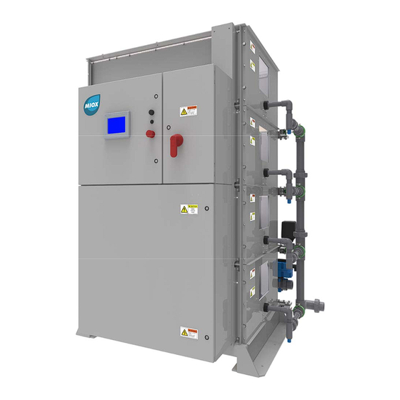
MIOX RIO-S Series Operators Manual System Description The MIOX RIO-S system is an on-site disinfectant generator that creates a disinfectant solution from water, salt, and electricity. The system can create 250-1200 lbs. of Free Available Chlorine (FAC) per day for the Mixed Oxidant model and 400-2000 lbs. FAC per day on the Sodium Hypochlorite model, depending on the number of modules installed and supplied voltage. -
Page 8: System Space Requirements
Security MIOX equipment must be installed in a building or protected structure that provides shelter from the weather and extreme temperature variances, and which can be locked or otherwise secured. Physical security is required to ensure that unauthorized persons cannot access the unit. -
Page 9: Figure 2: Rio-S Osg Space Requirements
MIOX RIO-S Series Operators Manual Figure 2: RIO-S OSG Space Requirements 102-00130-D Page 9... -
Page 10: Rio-S Components
The proprietary membrane-less electrolytic cell produces a mixture of oxidants and is manufactured by MIOX. For the MOS version, the RIO-S cell is configured to provide 62-75 lbs/day of Free Available Chlorine (FAC). There are 4 cells per cell bank providing 250-300 lbs/day FAC per cell bank with a maximum of four banks 1000-1200 lbs/day FAC. - Page 11 Plumbing and Fittings All plumbing and fittings shipped by MIOX meet Schedule 80 specifications. The U.S. specifications ensure that materials are rated for proper thickness, pressure requirements, and temperature resistance for the specific application.
-
Page 12: Figure 3: Front External View Of Rio-S With Labeled System Components
MIOX RIO-S Series Operators Manual Figure 3: Front External View of RIO-S with Labeled System Components 102-00130-D Page 12... -
Page 13: Installation Preparation
Disconnect power before working on the system. Do not reconnect the power to switch gear enclosure until installation is complete. All MIOX systems require a good earth ground. A neutral is not a substitute for a proper earth ground. Electrical wiring to all MIOX systems should be performed by a certified electrician. -
Page 14: Additional Installation Materials
Requirements section of this manual. The ambient air temperature at the installation location must be between 40°F (5°C) and 110°F (43°C). Additional space will be required for the water, brine, and oxidant tanks. MIOX recommends placing the OSG and tank near 102-00130-D... -
Page 15: Receiving And Unpacking The Rio-S Osg
MIOX RIO-S Series Operators Manual an available drain for ease of draining the tank or in case of minor overflows. Additionally, MIOX recommends placing the oxidant tank near an external wall for ease of hydrogen venting as described in the Hydrogen Safety White Paper. -
Page 16: Installing The Rio-S
Y-strainers via a 2” CPVC union. If needed, refer to Figures 4 and 5 for the locations of all major plumbing components, and below for a summary of the more operator-relevant components. If additional clarification is needed, contact your MIOX Customer Support provider. -
Page 17: Figure 4: Rio-S Major Plumbing Components (Non-Electrical)
Inlet/Outlet Plumbing Requirements All water and brine systems are compatible with schedule 80 PVC. MIOX strongly recommends schedule 80 CPVC for all mixed-oxidant or sodium hypochlorite solution connections and hydrogen venting. Where possible, all connections should be solvent welded rather than threaded to prevent the possibility of leaks. -
Page 18: Figure 5: External Plumbing Connections Required (3-Way Valve And Y-Strainers Not Shown)
Figure 5: External plumbing connections required (3-way valve and Y-strainers not shown) Sampling Valve Installation MIOX supplies a three-way valve to allow for sampling of the disinfectant solution to verify system performance. MIOX also supplies a check valve and strongly recommends installing the valve on the oxidant discharge line. -
Page 19: Electrical Overview
MIOX RIO-S Series Operators Manual Table 1: Feed Water Requirements 1-Bank 2-Bank 3-Bank 4-Bank 480V Flow GPH (LPH) 380 (1438) 760 (2877) 1140 (4315) 1520 (5754) 400V Flow GPH (LPH) 304 (1150) 608 (2300) 912 (3450) 1216 (4600) Electrical Overview The RIO-S operates at high voltage in close vicinity to water. -
Page 20: Figure 6: Electrical Cabinet Overview
MIOX RIO-S Series Operators Manual Figure 6: Electrical cabinet overview Main Power Cabinet: The main power cabinet holds the main breaker for the OSG. This is where power is routed into the OSG for distribution. The breaker’s amperage rating varies based on the number of cell banks installed with one, two, three, and four bank units being equipped with 100A, 200A, 300A, and 400A breakers respectively. -
Page 21: Figure 7: Main Power To Rio-S Osg
NOTE: Failure of the system that can be traced to a poor power source is not covered under the MIOX warranty. All MIOX systems require a good earth ground. A neutral is not a substitute for an earth Safety ground. Electrical wiring to all MIOX units should be wired on a separate circuit from other power devices (pumps, etc.). -
Page 22: Figure 8: Internal View Of Controls Cabinet Showing Major Electrical Components
MIOX RIO-S Series Operators Manual Figure 8: Internal view of Controls Cabinet showing major electrical components Programmable Logic Controller (PLC) The Programmable Logic Controller acts as the controlling unit of the OSG, this monitors and controls all functions of the OSG. - Page 23 Figure 9 for the locations of all major electrical components, and below for a summary of the more operator-relevant components. If there is an event where additional clarification is needed, please contact your MIOX Customer Support provider. 102-00130-D Page 23...
-
Page 24: Figure 9: Internal View Of Switchgear Cabinet Showing Major Electronic Components
MIOX RIO-S Series Operators Manual Figure 9: Internal view of Switchgear Cabinet showing major electronic components Cell Bank Circuit Breakers One per cell, individual resettable 80A circuit breakers for each cell bank in the system (max 4). Diode Temperature Switch - Thermostats One to three thermostats per unit, depending on capacity - located between diodes. -
Page 25: Figure 10: Modules 1 & 2 M12 Designations
MIOX RIO-S Series Operators Manual Monitors input voltage to the system for irregularities in phase and/or voltages that are outside of the specified operating range of the OSG Diodes One per cell bank, make up a 3-Phase rectifier in order to rectify feed voltage to be within the cells’... -
Page 26: Figure 11: Left View Of Rio-S Showing External Connections (Cell Enclosure Hidden)
All of the external connections are located on the left hand side of the cabinet. Refer to Figure 11 for the locations of all the side-panel connections. If additional clarification is needed, please contact MIOX Customer Support. Figure 11: Left View of RIO-S Showing External Connections (Cell Enclosure Hidden) ... -
Page 27: Water Boost And Brine Boost Relays Utilize High Voltage
M12 connection to the OSG that enables and provide status of the dilution air blowers (if equipped). The dilution air system dilutes the hydrogen gas produced from the oxidant tank to safe concentrations before venting to the atmosphere. Refer to MIOX’s Hydrogen Safety Whitepaper for more information on dilution air systems. ... -
Page 28: Figure 12: Typical Cell Bank Wiring Diagram: Top View
These components are all wired from the factory. If needed, refer to the sub-sections below for information on connecting the cells to power. If additional clarification is needed, please contact MIOX Customer Support. Figure 12: Typical Cell Bank Wiring Diagram: Top View ... -
Page 29: Panels Are Interlocked For Your Safety. Cells Operate At High
These components are all wired from the factory, but if needed, refer to Figures 13 and 14 as well as the component descriptions below for more information. If additional clarification is needed, please contact MIOX Customer Support. 102-00130-D Page 29... -
Page 30: Figure 13: External Plumbing Electrical Overview: Rear
MIOX RIO-S Series Operators Manual Figure 13: External Plumbing Electrical Overview: Rear 102-00130-D Page 30... -
Page 31: Figure 14: External Plumbing Electrical Overview: Right (Outlet)
MIOX RIO-S Series Operators Manual Figure 14: External Plumbing Electrical Overview: Right (Outlet) 102-00130-D Page 31... - Page 32 MIOX RIO-S Series Operators Manual Water Control Valve Operated by the PLC to control the flow rate of water entering the cells. Brine Solenoid Valve Operated by the PLC to start/stop the flow of brine to the brine pumps.
-
Page 33: Figure 15: Modules 3, 4 & 6 M12 Designations
MIOX RIO-S Series Operators Manual Cell Enclosure M12 Connections The RIO-S OSG comes equipped with three M12 connection modules (Modules 3, 4 and 6) on the plumbing assembly that connect all the devices on the plumbing assembly to the PLC. There is also a M12 connection module (Module 5) located inside Bank 2 that connects all of the panel interlocks. -
Page 34: Plumbing/Installing The Brine Tank
Note: Use Teflon tape on threaded plumbing connections. Brine Tank Float and Spray Ring Assembly MIOX has adapted an off-the-shelf float valve and spray ring assembly for providing saturated brine to the on-site generator. Kinetico® provides KCBS (Kinetico® Central Brine System) which includes a float valve assembly with a 28”... -
Page 35: Figure 17: Brine Tank Float Assembly
MIOX RIO-S Series Operators Manual Figure 17: Brine Tank Float Assembly The spray ring assembly provides a more consistent means of mixing the salt and water to meet the brine saturation requirement. The spray ring at the top of the tank eliminates possibility of channeling (or short circuiting) the water through the outlet of the tank. -
Page 36: Brine Boost System Installation (Optional)
Quartz Rock In order to accommodate various salt types, MIOX provides a cross-shaped, slotted pipe manifold. Thread the manifold into the bottom tank adapter. Place 7 inches of ½” x ¼” NSF quartz rock in the bottom of the tank. Rake it flat and cover the slotted pipe manifold. Place 5 inches of ¼”... -
Page 37: Figure 19: Brine Pressure Boost System
MIOX RIO-S Series Operators Manual Figure 19: Brine Pressure Boost System 102-00130-D Page 37... -
Page 38: Plumbing/Installing The Oxidant Storage Tank
0.5 in. per foot (1.3 cm per meter), sloping towards the tank. If the oxidant tank is not supplied by MIOX, a drop tube assembly and LBS vent assembly must be fabricated on-site. Refer to MIOX’s Hydrogen Safety Whitepaper for information on how to properly fabricate a Hydrogen Mitigation System. -
Page 39: Figure 21: Oxidant Tank Safety Placard Locations
Safety placards are required on oxidant tanks and are attached to all oxidant tanks shipped directly from MIOX. Oxidant tanks shipped directly from the tank manufacturer must have the MIOX supplied safety placards attached to the outside wall of the oxidant tank. Figure 21: Oxidant Tank Safety Placard Locations... -
Page 40: Figure 22: Hydrogen Ventilation Requirements
White Paper and this manual must be followed explicitly to ensure proper hydrogen venting MIOX oxidant tanks require that they be vented to the atmosphere outside the facility. Proper configuration of vent assemblies (Figure 22) is vital to ensure safety. -
Page 41: Figure 23: Oxidant Pressure Transducer Assembly
Figure 23: Oxidant Pressure Transducer Assembly Level Switch Installation For MIOX-supplied oxidant storage tanks, the level switch is shipped loose in the tank. If the oxidant storage tank is not shipped with the RIO-S OSG, the switch is shipped separately. -
Page 42: Figure 24: Level Switch Installation
MIOX RIO-S Series Operators Manual The switch is designed to operate with the RIO-S OSG. To install the level switch in the tank, complete the following steps: 1. Wrap the male end of the street elbow with Teflon tape and connect it inside the solution tank into the ½”... - Page 43 The injection system should be designed by a qualified engineer, MIOX distributor or salesperson. Note: Refer to Injection System Manufacturer’s Manual for installation guidelines.
-
Page 44: Operation Of The Rio-S
MIOX RIO-S Series Operators Manual OPERATION of the RIO-S Initial Startup Before performing the initial startup of your RIO-S OSG, make sure to perform these tasks: Electrical Check Verify connection to correct power source, nominal 400-480 VAC, three-phase, 50-60 hertz. - Page 45 MIOX RIO-S Series Operators Manual Water Softener Operation. Ensure that the water softener is operating properly before initial startup by testing the water from the water softener for hardness. If hardness is more than 1 grain per gallon (17.1 ppm), the softener is not functioning properly.
-
Page 46: Normal Operation
MIOX RIO-S Series Operators Manual Normal Operation In normal operation, the RIO-S automatically enters ‘Run’ and ‘Standby’ modes based on the oxidant level in the oxidant tank. For self-cleaning models, The RIO-S will also automatically enter a ‘Cleaning’ mode on the first startup after a predefined number of operating cell hours. -
Page 47: Interface Elements
MIOX RIO-S Series Operators Manual Note: If you have excessive stops and starts, the oxidant solution will be diluted due to start-up and shutdown flushes. Brine Boost Pump Commissioning The brine boost pump is electrically interlocked with the OSG. Once the OSG is in Run mode, the pump will run. -
Page 48: Figure 25: Hmi Main Screen
MIOX RIO-S Series Operators Manual Figure 25: HMI Main Screen Emergency Stop (E-Stop) Button Completely shuts down the OSG. For use if an event arises where the unit must be shut down immediately. Pour une utilisation si un événement survient lorsque l'appareil doit être arrêté... - Page 49 MIOX RIO-S Series Operators Manual Fault may appear due to the loss of 3-phase power. The same E-Stop shut down sequence occurs when the switchgear door interlock is tripped. The reset procedures for both are very similar: E-Stop Reset 1. Reset E-Stop button by pulling button outward.
-
Page 50: Communications
The interface can be configured to support e-mail and SMS notification if the system shuts down for a fault that requires operator attention. A ModBus/Ethernet IP is built into the PLC as a standard. For other communication options available, contact MIOX Customer Support provider. -
Page 51: Modes Of Operation
MIOX RIO-S Series Operators Manual Modes of Operation The modes of operation of the OSG are: Standby, Startup, Run, Self Clean, Stop, Diagnostics and Shutdown. Normal operational sequencing involves entering Run mode to fill the oxidant tank. Once the oxidant tank is full, the OSG transitions to Shutdown and then Standby mode. -
Page 52: Figure 26: Hmi Cell Bank Manual Enable/Disable Interface
MIOX RIO-S Series Operators Manual Diagnostic Mode Diagnostic mode allows the user to individually test each output. Diagnostic mode is only accessible from Stop mode. Diagnostic mode is accessed from a button on the main screen. Once in Diagnostic Mode, the operator can monitor inputs and toggle outputs. Once the operator leaves the Diagnostic page, all I/O are set to off. -
Page 53: Long Term System Shutdown Procedure
This sequence for shutdown of the RIO-S OSG is designed to properly flush the electrolytic cell and help maintain the overall condition of the MIOX equipment. When turning the system off for a prolonged period of time, it is important to follow this sequence: 1. -
Page 54: Troubleshooting
MIOX RIO-S Series Operators Manual Troubleshooting Fault Conditions The RIO-S is preprogrammed with a number of fault conditions which trigger whenever the system is running atypically. The faults are classified as either hard or soft faults. Hard faults automatically shut the system down and require a power cycle to reset the system. - Page 55 MIOX RIO-S Series Operators Manual Fault Name Condition Time Cell Flush Auto Delay Power Removed Retry (sec) Removed Low Low Water Flow 50% decrease in water flow rate – immediate response High Flow Flow rate increase above specified set- point...
-
Page 56: Troubleshooting Guide
MIOX RIO-S Series Operators Manual Troubleshooting Guide Table 3: Fault Conditions Troubleshooting Guide System Display Fault Cause (most likely Remedial Action to least likely) Leak Detected – Liquid detected on 1) Excessive water 1) Verify pressure in Bank 1-4 cell bank sensing pressure in cell cell plumbing <25... - Page 57 MIOX RIO-S Series Operators Manual System Display Fault Cause (most likely Remedial Action to least likely) Oxidant or Water Panel removed with 1) Panel removed 1) Replace panel and Side Panel Open – power applied to prior to follow Manual Reset...
- Page 58 MIOX RIO-S Series Operators Manual System Display Fault Cause (most likely Remedial Action to least likely) High Flow Control Flow control is not 1) Valve open but 1) Verify water flow Signal reaching target set- not seeing any and pressure is...
- Page 59 MIOX RIO-S Series Operators Manual System Display Fault Cause (most likely Remedial Action to least likely) Loss of SCADA Connection to 1) External SCADA 1) Verify SCADA is SCADA is lost connection to providing signal OSG is lost 2) Contact MIOX...
-
Page 60: Water Flow Control Valve Re-Set Procedure
6. Plug in the control signal DIN plug. 7. Tighten the screws that hold the plugs in place. 8. The actuator should function properly again. If not, contact MIOX. Note: Open the inlet water valve after completing re-set procedure. 102-00130-D... -
Page 61: Electrolytic Cell Replacement
You may return a defective product to your original point of purchase, or the authorized MIOX dealer or distributor from whom you purchased the product. Please confirm the terms of its return policies prior to returning the product. Typically, you must include product... -
Page 62: Maintenance
MIOX recommends keeping a minimum of 1 foot (0.3 meters) of salt in the brine generator at all times. Note: During the first few weeks of operation, it is critical to check the MIOX OSG more frequently to identify and solve site-specific problems, fine tune the injection rate and tighten any connections that may have loosened during shipping. -
Page 63: Weekly Maintenance
If water pressure goes below 60 PSI (414 kPa) or above 100 PSI (689 kPa), it could damage the MIOX OSG. For 1-3 banks systems, the minimum feed water pressure is 50 PSI (345 kPA). -
Page 64: Quarterly Maintenance
MIOX RIO-S Series Operators Manual Quarterly Maintenance Clean Brine Tank – Using a wet rag, wipe down the interior of the brine generator tank wall to remove any dirt or buildup. Clean or Replace the Brine Filter and Water Filter – The brine and water filters are the same 5-micron standard type unit for removal of particulate matter. -
Page 65: Rupture Disk
MIOX RIO-S Series Operators Manual Rupture Disk Each cell bank of the RIO-S OSG is equipped with a designated rupture disk. The rupture disk is designed to prevent excessive pressure build up inside the cell. If the cell pressure exceeds 25 PSI, a diaphragm inside of the rupture disk union bursts. Flow is routed towards leak detector sensing band, which will trigger Leak Detect Fault. -
Page 66: Figure 29: Ruptured Diaphragm
6. Remove the damaged disk and replace with a new one. Replacement disks have been furnished with the OSG operations kit. If more disks are needed contact MIOX customer service or other appropriate service representative. 7. Carefully thread the union back together with the disk centered inside 8. -
Page 67: Leak Detection
4. If the leak cannot be traced to a loose fitting or union, DO NOT resume operation of the OSG as it can lead to significant additional damage to the system and present a safety hazard. Contact MIOX Customer Service for assistance. 5. Clean and dry the leak detector sensing band using the following steps: a. -
Page 68: Acid Washing Cell
MIOX RIO-S Series Operators Manual Acid Washing Cell Water with hardness of greater than 1 grain/gallon (17.1 mg/L as CaCO3) feeding the MIOX generator will coat the plates within the cell with solid impurities such as calcium carbonate. Calcium carbonate (CaCO3) is usually white in color but can be other colors depending on dissolved salts in the water. - Page 69 1. Determine the amount of oxidant and sample water to be used. Always start with start with a 5 ppm dose for the first test. Suppose you are using a MIOX OSG that just generated an oxidant solution concentration of 250 ppm. First, you must determine the...
- Page 70 MIOX RIO-S Series Operators Manual Determine the oxidant and sample water volumes for the 1, 3, and 5 ppm doses. Given that MIOX OSG is still generating an oxidant concentration of 250 ppm. 1 ppm 3ppm 5ppm Dilution Factor (X) 250/1 = 250 250/3 = 83.3...
-
Page 71: Chlorine Production Testing
Equipment Needed • 250 mL glass beaker • 3000 mL, or 5000 mL glass jar with lid (depending on MIOX OSG being tested) • Pipette that can accurately measure 0.5 mL or 1 mL samples • Chlorine Test Kit (i.e. DPD, Color Wheel, Colorimeter or AccuVac) •... - Page 72 MIOX RIO-S Series Operators Manual • Graduated Cylinder (1000 mL for MIOX and RIO Series mixed-oxidant or sodium hypochlorite systems) • Timer or a watch with a second hand • Calculator Preparing Chlorine Demand-Free Water Demand-free water is required for determination of oxidant concentration in an on-site generator.
- Page 73 5000 mL line with demand-free water, depending on which dilution technique you are using: • MIOX Series Systems: Use a 1:2500 ratio (= 1.0 mL solution to 2500 mL water or 2 mL solution to 5000 mL water.) • HYPO Series Systems: Use a 1:5000 ratio (= 1 mL solution to 5000 mL water) 3.
- Page 74 MIOX RIO-S Series Operators Manual 2.25 mg/L – 0.5 mg/L = 1.75 mg/L net 1.75 mg/L x 2500 = 4375 mg/L 8. Repeat this process three times, take the average of these readings and assign this value to X to calculate chlorine production.
- Page 75 MIOX RIO-S Series Operators Manual X = mg/L chlorine concentration Y = gph flow 102-00130-D Page 75...
-
Page 76: Appendices
These factors can affect the oxidant demand of each individual water system, the oxidant production of the MIOX system, or the life of the cell itself. It is important to use “worst case” measures since water quality can vary from season to season. -
Page 77: Appendix B - Salt Quality Guidelines
Follow the system specifications for absolute limits. Appendix B – Salt Quality Guidelines MIOX requires that all Self Cleaning RIO-S Systems use a granular salt that meets or exceeds the purity percentages listed below. For additional information consult the MIOX Salt Guidelines white paper (P/N: 106-00008).
Need help?
Do you have a question about the RIO-S Series and is the answer not in the manual?
Questions and answers