Table of Contents
Advertisement
Quick Links
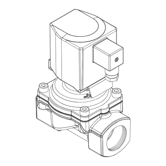
Operation manual -
pre-controlled diaphragm valves
with forced lifting
Revision 8
Keep documentation for future use!
Series
82540
82640
G
N
82590
84490
G
N
G-Thread
G
N
NPT-Thread
11/2018
Contents
1.1 Documentation validity
1.2 Structure of safety instructions
14
14
14
14
14
14
14
Translation of the original operating manual
Status as of November 2018
1
1
About this documentation
1
1
These mounting instructions guides you to
1
mount, operate and maintain pre-controlled
2
diaphragm valves with forced lifting safely.
2
2
This operation manual is intended for:
2
plant operators, installers, maintenance and
2
service technicians.
2
2
1.1
Documentation validity
3
This operation manual applies to the following
3
3
series
3
•82540, 82590 (G-Thread)
4
•82640, 84490 (NPT-Thread)
4
•for special products that are based on the
4
series mentioned above
4
5
in combination with these solenoid:
5
Series
9151
9301
5
5
9154
9304
x
x
5
9176
9356
6
x
x
9191
9326
7
7
82540
G
•
•
7
82590
G
•
7
82640
N
•
•
7
7
84490
N
•
7
7
Order No.
Connection
Connection
7
xxxx0xx
G 1/4
1/4 NPT
8
8
xxxx1xx
G 3/8
3/8 NPT
8
xxxx2xx
G 1/2
1/2 NPT
8
8
xxxx3xx
G 3/4
3/4 NPT
8
xxxx4xx
G 1
1 NPT
xxxx5xx
G 1 1/4
1 1/4 NPT
xxxx6xx
G 1 1/2
1 1/2 NPT
xxxx7xx
G 2
2 NPT
Series
82540,
82640,
82590
84490
1.2
Structure of safety instructions
Safety instructions warns against dangerous
situations and must be observed in particular.
Safety instructions are structured as follows:
SIGNAL WORD
Type of hazard
Consequences of non-observance
→ Precautions necessary to avoid the hazard
1.3
Hazard classes (ANSI Z535.6)
!
DANGER
Safety information indicates a hazardous situation
with high risk which, if not avoided, will certainly
result in death or (serious) injury.
!
WARNING
Safety information indicates a hazardous situation
with moderate risk which, if not avoided, can cause
9401
death or severe injury.
9404
!
CAUTION
Safety information indicates a hazardous situati-
•
on which, if not avoided, could result in minor or
moderate injury.
•
•
NOTICE
•
Information indicates a hazardous situation which,
if not avoided, could result damage to property.
1377006.0000.10011
1
Advertisement
Table of Contents

Related Manuals for IMI BUSCHJOST 82590G Series

Summary of Contents for IMI BUSCHJOST 82590G Series
-
Page 1: Table Of Contents
Contents Translation of the original operating manual Structure of safety instructions Status as of November 2018 1 About this documentation Safety instructions warns against dangerous situations and must be observed in particular. 1.1 Documentation validity About this documentation Operation manual – 1.2 Structure of safety instructions Safety instructions are structured as follows: pre-controlled diaphragm valves... -
Page 2: Styles And Symbols
→ The instructions given in this operation knowledge about design and principle of ope- Improper use manual must be put into practice. ration of the valves and the plant. In the following cases it is prohibited to opera- → This documentation must be available at te the valve: Personal protection equipment any time. -
Page 3: Avoid Damage To Property
Identifying the valve Transport and storage Hazardous fluids The rating plate is situated on the solenoid Phases: assembly, operation, NOTICE body. maintenance, disposal Damage of the valve Risk: skin contact, eye contact, DANGER Valve may be damaged if foreign particles breathing vapors Made in Germany Hazardous electrical voltage... -
Page 4: Nc-Valve (Normally Closed)
Switching position: open Normal position: open Mounting The magnetic force lifts the core towards When the solenoid is de-energized, the pilot NOTICE the magnet face of core tube when the seat is opened by the effect of the com- 7 4 ... -
Page 5: Valve Dimensions In Mm
Mounting accessories Conditions of installation Mounting bracket Compliance with operating limits With an optional mounting bracket, you can Ensure to comply with the operating limits pri- Valve dimensions in mm connect the valve to an load-bearing structure or to mounting the valve. Observe the valve’s at the installation site, thus protecting against data sheet. -
Page 6: Connecting Solenoid Electrically
Connecting solenoid electrically 2. Attach the protective conductor at first (insulation: yellow/green) to the terminal → Always connect the device socket which marked with the grounding symbol was delivered by Buschjost. 1. Take out the blanking plugs 1 from valve inlet and valve outlet. -
Page 7: Operating Conditions
Commissioning Maintenance Checking internal tightness 1. Close the valve (NC valve: solenoid de-ener- Maintenance work must only be carried out CAUTION gized; NO valve: solenoid energized). by qualified personnel (refer to section Danger through escaping fluid 2. Flood the valve. Deposits of the medium, dirt particles, aged or solenoid 9176... -
Page 8: Document No. 1377006.0000.10011 Revision
12.6 12.8 12.9 Replacing spare parts Lubricating valve parts accordingly Valve-specific disassembly/ reassembly perform after disassembly perform prior to reassembly NC valves* 12.4 Checking valve parts CAUTION NOTICE perform after disassembly solenoid 9151 9154 9176 9191 Risk of injury caused through the Damage of the valve The installation of wrong components may installation of wrong parts... - Page 9 Disassemblingh valve parts Mounting solenoid NC valve 1. Loosen core tube 701 (wrench size 22). 1. Push o-ring 707 onto core tube until the solenoid 9151 9154 9176 9191 2. Take off core tube 701 together with spring o-ring is flush to screw piece 703. clip 706 from core 705.
- Page 10 Disassemblingh valve parts Mounting solenoid NC valve 1. Loosen core tube 701 (wrench size 22). 1. Push O-ring 1502 onto core tube 701 until solenoid 9301 9304 9356 9326 2. Take off core tube 701 from core 705. it rests smooth on the tube‘s basis. 2.
- Page 11 9. Mount spring clip 706 on the guide shoulder Disassemblingh valve parts NC valve of the screw sleeve of core tube 701. 1. Loose core tube 701 (wrench size 36). solenoid 9401 9404 10. Slide core tube 701 over core 705 on 2.
- Page 12 6. Put O-rings 706 and 707 in the groove of Disassemblingh valve parts NO valve pole piece 705. 1. Loosen core tube 701 at screw piece solenoid 9151 9154 9176 9191 7. Place pole piece 705 over valve spindle 105 (wrench size 22).
- Page 13 11. Insert straight pin 706 flush to fix the core Disassemblingh valve parts NO valve 702 to diaphragm 103. 1. Loosen core tube 701 (wrench size 18). solenoid 9301 9304 9356 9326 12. Slide core tube 701 over core 702 and 2.
-
Page 14: Re-Commissioning
Re-commissioning Trouble shooting Disposal → Observe safety information and instructions 1. Check valve’s switching function without 1. Disassemble the valve as described in chap- fluid (refer to in chapter “Maintenance”. “Decommissioning”. 10.1 12 14 2. Flood the valve slowly (refer to 2.
Need help?
Do you have a question about the 82590G Series and is the answer not in the manual?
Questions and answers