
Related Manuals for WAGNER Titanus Micro-Sens


Summary of Contents for WAGNER Titanus Micro-Sens
- Page 1 Air sampling smoke detection system Fire Detection MICRO·SENS TITANUS ® Technical Manual...
- Page 3 Air sampling smoke detection system MICRO·SENS TITANUS ® Technical Manual WAGNER Group GmbH Item Number 69-30-0525 Schleswigstraße 1 - 5 D-30853 Langenhagen Edition 06/13 Telephone +49 (0) 511 / 97383-0 Telefax +49 (0) 511 / 97383-140 Supersedes 01/09 E-Mail support@wagner.de Internet www.wagner.de...
-
Page 5: Table Of Contents
MICRO·SENS TITANUS ® Contents General Introduction Safety information Guarantee Copyright Packaging Disposal Product Description Characteristics of the TITANUS MICRO·SENS® aspirating smoke detection system Areas of Application Technical Description System Description 3.1.1 Function MICRO·SENS TITANUS and Accessories ® 3.2.1 Overview 3.2.2 Air sampling smoke detection system 3.2.3 Detector box... - Page 6 MICRO·SENS TITANUS ® 3.3.2.1 Aspiration reduction films 3.3.2.2 Aspiration reduction clips 3.3.3 Ceiling duct for concealed mounting 3.3.4 Air filters for dusty areas 3.3.5 Air return for pressure differences and air pollution 3.3.6 Noise suppressor 3.3.7 Steam trap for humid areas Technical Data MICRO·SENS TITANUS...
- Page 7 MICRO·SENS TITANUS ® 5.3.1 Project planning for individual aperture monitoring 5.3.1.1 I-Pipe system 5.3.1.2 U-Pipe system 5.3.1.3 M-Pipe system 5.3.1.4 Double-U-Pipe system 5.3.2 Simplified pipe design 5.3.2.1 I-Pipe system 5.3.2.2 U-Pipe system 5.3.2.3 M-Pipe system 5.3.2.4 Double U-pipe system 5.3.3 Project planning with branch pipe 5.3.4 Project design for forced air flow...
- Page 8 MICRO·SENS TITANUS ® 6.7.2 Function switching plan, relay board RU-2 MICRO·SENS TITANUS in the network ® MICRO·SENS 6.8.1 Installing the network module in the TITANUS ® MICRO·SENS 6.8.2 Connecting the network module to the TITANUS ® Remote displays MICRO·SENS 6.9.1 Connecting the Remote displays to TITANUS ®...
- Page 9 MICRO·SENS TITANUS ® Installation Pipe System General assembly 7.1.1 Mounting pipe system 7.1.2 Mounting air sampling hose Linear expansion of the pipe system Patented air sampling points Ceiling lead through 7.4.1 Ceilings feed-through for false ceiling 7.4.2 Other ceilings feed-through Monitoring in forced air flow systems (ventilation or climatic applications) 7.5.1...
- Page 10 MICRO·SENS TITANUS ® Commissioning Commissioning the detection unit 8.1.1 Plug and Play Commissioning 8.1.2 Commissioning with the diagnostics tool Installing diagnostics software Air flow sensor adjustment 8.3.1 Air Pressure-Independent Adjustment 8.3.2 Air Pressure-Dependent Adjustment Testing the detection unit and alarm forwarding Testing air flow monitoring Testing fault forwarding Testing the air flow sensor analysis function...
- Page 11 MICRO·SENS TITANUS ® Checking the air flow sensor adjustment 9.10 Testing fire seat location and the reaction indicators 9.11 Testing Air Flow Monitoring 9.12 Testing Fault Forwarding 9.13 Maintenance Intervals Appendix Projection Tables System Product List Inspection Protocol Glossary Conformity certification pursuant to EU 06/13...
-
Page 13: General
For damage and faults resulting from the non-observance of this manual WAGNER Group GmbH, called WAGNER in the following, does not assume liability. This manual refers to the air sampling smoke detection systems TITANUS MICRO·SENS... -
Page 14: Guarantee
▪ force majeure Copyright The copyright in this Technical Manual remains with WAGNER. The manual is designed exclusively for the assembler and his col-leagues. Reproduction of the manual, including extracts, is not allowed. Copying or distribution of the manual in any form is only allowed with permission in writ- ing from WAGNER. -
Page 15: Disposal
▪ Take metal parts for scrapping. ▪ Take plastic parts to be recycled. ▪ Sort the remaining components by material quality and dispose of them. ▪ Give batteries to municipal collecting points, or send them back to WAGNER Group GmbH. 06/13... -
Page 17: Product Description
MICRO·SENS Characteristics of the TITANUS ® aspirating smoke detection system MICRO·SENS TITANUS is the latest generation of the renowned WAGNER ® MICRO·SENS smoke detection systems. The can be used for room and ® equipment protection and for monitoring air conditioning cabinets or air con- ditioning ducts. - Page 18 MICRO·SENS TITANUS Product Description ® Airflow monitoring is temperature-compensated and can be set to be air pressure-dependent. MICRO·SENS Plug and Play Installation and commissioning of the TITANUS are simple ® with the Plug & Play function. The device base is pre-assembled on site. By pre-setting the detection unit MICRO·SENS for standard applications, the TITANUS is operational imme-...
- Page 19 Product Description ® Patented detection points Wagner’s patented detection reducing films, clips and banderols make as- sembly simple and comfortable and avoid whistling operational noises. An even inflow of air through all the apertures is achieved with a stepped aper- ture diameter.
-
Page 20: Areas Of Application
MICRO·SENS TITANUS Product Description ® Areas of Application MICRO·SENS The TITANUS air sampling smoke detection system is a fire ® alarm system for the protection of rooms, equipment and air conditioning ducts. Principle Air samples for a monitoring area are taken through the draw-off holes in a pipe system and fed to the detection unit. - Page 21 MICRO·SENS TITANUS Product Description ® MICRO·SENS Room protection The TITANUS is suitable, for example, for monitoring rooms ® such as, e.g. ▪ double floors, intermediate ceilings, ▪ tunnels, ducts, cavities not easily accessible, ▪ warehouses, deep freeze stores, lift shafts, ▪...
- Page 22 MICRO·SENS TITANUS Product Description ® Room monitoring with air Room monitoring takes place... conditioning ▪ in server rooms with air conditioning, ▪ in ventilation ducts, ▪ in double floors, intermediate ceilings, ▪ in IT rooms, E-distribution rooms, transformer cells, ▪ for air conditioning cabinets (see Fig. 1.2), ▪...
- Page 23 MICRO·SENS TITANUS Product Description ® Device protection unventilated and force-ventilated equipment / cabinets such as, e.g. ▪ distribution cabinets, switching cabinets ▪ telephone switching equipment ▪ measuring, control and regulation equipment Figure 3: Equipment monitoring principle with air sampling smoke detection system 06/13...
-
Page 25: Technical Description
MICRO·SENS TITANUS Technical Description ® Technical Description System Description MICRO·SENS The TITANUS aspirating smoke detection system comprises ® a detection unit, device base and pipe system. MICRO·SENS The most important components of the TITANUS are the ® sensitive detection unit for picking up smoke aerosols and the aspiration unit with integrated air flow sensor for transporting air samples and for monitoring the pipe system for breaks and blockages. -
Page 26: Function
MICRO·SENS TITANUS Technical Description ® 3.1.1 Function Air samples are taken from the area to be monitored via a pipe system with MICRO·SENS defined aspiration apertures, using the TITANUS aspiration ® unit and these are sent to the sensitive detection unit (see the following fig- ure). - Page 27 MICRO·SENS TITANUS Technical Description ® Figure 6: Phase 2 ROOM·IDENT earliest fire detection Phase 3 In case alarm or at function „Fire alarm after ROOM·IDENT“ once the system has reached the adjustable action the aspiration fan is switched off and a second fan is switched on, blowing out the smoke particles in the opposite direction.
- Page 28 MICRO·SENS TITANUS Technical Description ® Figure 8: Phase 4 ROOM·IDENT localisation MICRO·SENS The alarm is indicated on the TITANUS itself, indicated ® within the monitored area via an optical external alarm indicator. The System with enabled option „Fire alarm after ROOM·IDENT“ will now activate an alarm Detection Depending on the reaction sensitivity of the detection unit used (which can...
- Page 29 MICRO·SENS TITANUS Technical Description ® alarm point via a contact. The monitoring windows can be adjusted to the environmental conditions. The principle of the airflow sensor signalling process can be seen in the fol- lowing figure. Figure 9: Example signal pattern in the airflow sensor during faults Device monitoring The detection unit is monitored for dirt and signal fault.
-
Page 30: Titanus Micro·sens ® And Accessories
MICRO·SENS TITANUS Technical Description ® MICRO·SENS TITANUS and Accessories ® 3.2.1 Overview Connections FAS / Power supply Pipe systems ® TITANUS Air return feed to the next smoke detection system E Indicator bus Additional housing (optional) Fire alarm cable Relay platine RU-2 (optional) Relay board RU-1 (optional) -
Page 31: Air Sampling Smoke Detection System
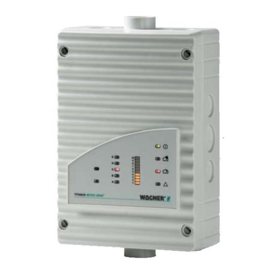
MICRO·SENS TITANUS Technical Description ® 3.2.2 Air sampling smoke detection system MICRO·SENS The TITANUS air sampling smoke detection system com- ® prises the following components, device base, detection unit and pipe sys- tem: Device base ▪ Connections for 25 mm aspiration pipe (in and return) ▪... - Page 32 MICRO·SENS TITANUS Technical Description ® Figure 12: TITANUS MICRO·SENS display variant with smoke levels and fire loca- ® tion MICRO·SENS TITANUS ® Numbers Function Explanation Smoke level display 1 to 10 (10 yellow LEDs) (*) Current smoke level Operation (green LED) Operation display Fire alarm (red LED) Smoke level (where fire...
-
Page 33: Detector Box
MICRO·SENS TITANUS Technical Description ® 3.2.3 Detector box External detector boxes can be used in the pipe system in connection with MICRO·SENS the TITANUS smoke detection system. ® The detector box is used … ▪ to create a two-detector or two-line dependency, ▪... - Page 34 MICRO·SENS TITANUS Technical Description ® Figure 14: TITANUS MICRO·SENS function principle with detector box for locating ® and raising reaction sensitivity MICRO·SENS The TITANUS detector box comprises the following compo- ® nents: Device base ▪ Connections for 25 mm aspiration pipe (in and out) ▪...
- Page 35 MICRO·SENS TITANUS Technical Description ® Figure 15: Detector box displays and connections Figure 16: Display variant, detector box with smoke level and action alarm 06/13...
- Page 36 MICRO·SENS TITANUS Technical Description ® Detector box Numbers Function Explanation Smoke level display 1 to 10 (10 yellow LEDs) (*) Current smoke level Operation (green LED) Operation display Fire alarm (red LED) Smoke level (where fire alarm threshold is set) Action alarm (red LED) (*) Smoke level (Value as per fire alarm threshold 10 –...
-
Page 37: Diagnostics Tool
MICRO·SENS TITANUS Technical Description ® 3.2.4 Diagnostics tool Figure 17: Diagnostics tool for inputting and reading off device data Using the DIAG 3 diagnosis tool, the device configuration for the TITANUS ® can be changed during commissioning. For maintenance and servicing, there is the option with the diagnosis software to display the stored and cur- rent device status and error messages from the TITANUS on a PC or lap-... -
Page 38: Network Modules
MICRO·SENS TITANUS Technical Description ® 3.2.5 Network Modules Figure 18: Network card NU-2 The log data and status information of all TITANUS air sampling smoke de- ® tection systems can be stored with the TITANUS network card. For applica- ® tions in cold storage, special network modules for the TITANUS available. - Page 39 MICRO·SENS TITANUS Technical Description ® intervals of 1-60 seconds. The logged data saved can be analysed in the TI- TANUS DataView and TITANUS EventView software programs supplied. ® ® Web server For network modules with embedded web server, it is possible to display current data and status information device specific on a predefined display panel and is easily accessible via a standard Web browser.
-
Page 40: Remote Displays
MICRO·SENS TITANUS Technical Description ® 3.2.6 Remote displays Figure 19: Remote display for wall mounting MICRO·SENS The TITANUS offers the possibility of connecting one or ® more remote displays. The displays on the remote display are identical to those on the detection unit. The connection is made in the TITANUS CRO·SENS device base. -
Page 41: Reaction Indicator
MICRO·SENS TITANUS Technical Description ® 3.2.7 Reaction indicator Figure 20: Reaction indicator for locating the site of a fire MICRO·SENS When the TITANUS is used with fire location, up to 5 ad- ® dressable reaction indicators can be used via the indicator bus. The r eaction indicator can be connected up to a distance of 1000 m. -
Page 42: Pipe System
MICRO·SENS TITANUS Technical Description ® Pipe system 3.3.1 Overview 90° arc Connections pipe system steam trap sleeve sampling hose- ceiling feed special filter through air filter T-piece 45°- elbow air sampling pipe 90° elbow test adapter TITANUS ® End cap air sampling non-return valve hose... - Page 43 MICRO·SENS TITANUS Technical Description ® quency of blockages, the blow-throng process can be undertaken manually or automatically. Figure 22: Components of the manual blowing-out system Figure 23: Components of the automatic blowing-out system 06/13...
-
Page 44: Aspiration Apertures For Room Monitoring
MICRO·SENS TITANUS Technical Description ® 3.3.2 Aspiration apertures for room monitoring 3.3.2.1 Aspiration reduction films Figure 24: Aspiration aperture with aspiration reduction film and banderol An air sampling point is a 10 mm-hole in the air sampling pipe covered with a patented aspiration-reducing film sheet with the appropriate opening diame- ter. -
Page 45: Aspiration Reduction Clips
MICRO·SENS TITANUS Technical Description ® 3.3.2.2 Aspiration reduction clips Figure 25: Air flow reducer for dirty areas and deep freeze storage The air sampling points, when used in areas where blockages can occur, are equipped with a patented plastic clip, type AK-C, and a patented flexible air flow reducer, type AK-x. -
Page 46: Ceiling Duct For Concealed Mounting
"Design". If - due to construction - hose lengths of more than 1 m are required, the air sampling pipe system must be calculated separately (calculation is made by WAGNER). The ceiling feed through is applicable for false ceiling panels with a thickness of up to approximately 35 mm. - Page 47 MICRO·SENS TITANUS Technical Description ® Pipe cap Air flow reducer (Aperture plate) Hose connection Ceiling feed through (part) Air sampling hose Figure 27: Capillary hose Installation and upstream aperture For hidden installation in example lamps or stucco, the air sampling hose with upstream aspiration reduction in the tees (pipe caps) are used.
-
Page 48: Air Filters For Dusty Areas
MICRO·SENS TITANUS Technical Description ® 3.3.4 Air filters for dusty areas Figure 28: TITANUS MICRO•SENS with air filter ® In areas with interference to the environment such as, e.g. dust, an air filter is to be used to protect the smoke detection system. Type LF-AD-x air filter The standard air filter used is the type LF-AD-x, consisting of a plastic hous- ing with two pipe connections, used. - Page 49 MICRO·SENS TITANUS Technical Description ® Figure 29: Special Filter and LF-AD The filter life of special filter can be increased by the use of an upstream filter LF-AD. LF-AD LF-AD LF-AD LF-AD ® TITANUS Figure 30: LF-AD filters in multiple sampling pipes 06/13...
- Page 50 MICRO·SENS TITANUS Technical Description ® In order to extend the maintenance intervals, one air filter can be installed in every output pipe instead of one air filter inside the main sampling pipe. The same design specifications shall apply as stated in the projection tables in the appendix.
-
Page 51: Air Return For Pressure Differences And Air Pollution
MICRO·SENS TITANUS Technical Description ® 3.3.5 Air return for pressure differences and air pollution Figure 32: Principle of air return with TITANUS MICRO· SENS ® MICRO·SENS If TITANUS and the pipe system are installed in two areas - ® P1 and P2 – each with different air pressures, the air must be returned to the pressure area of the pipe system. -
Page 52: Noise Suppressor
MICRO·SENS TITANUS Technical Description ® 3.3.6 Noise suppressor TITANUS MICRO·SENS ® SD-1 Figure 34: TITANUS MICRO·SENS with noise suppressor By using the SD-1 noise suppressor, the noise level can be reduced by up to 10 db(A) for use in areas in which low noise emissions are required from the MICRO·SENS TITANUS (such as in offices or hospitals). -
Page 53: Steam Trap For Humid Areas
MICRO·SENS TITANUS Technical Description ® 3.3.7 Steam trap for humid areas Figure 35: Steam trap to eliminate water vapour from the pipe system and to collect the condensate from the pipe system Figure 36: KA-1 to eliminate water vapour from the pipe system and to collect the condensate from the pipe system 06/13... - Page 54 MICRO·SENS TITANUS Technical Description ® MICRO·SENS The TITANUS is used in environments with high humidity ® condensate can occur in the air sampling system. In order to collect this condensate the steam trap is installed at the deepest point of the pipe sys- tem before the air filter and the air sampling smoke detection system.
-
Page 55: Technical Data
MICRO·SENS TITANUS Technical Data ® Technical Data NOTICE All power consumption figures relate to an ambient temperature of 20°C. MICRO·SENS TITANUS ® ® TITANUS MICRO·SENS Voltage Power supply (Ue) 16 - 30 V DC Nominal power supply 24 V DC Current 1= 9 V 1= 10.5 V... - Page 56 MICRO·SENS TITANUS Technical Data ® Protection classification Protection classification (EN 60 529) without air return IP 20 with pipe piece 100 mm/pipe bend IP 42 with air return IP 54 Housing material plastic (ABS) colour papyrus white, RAL 9018 Temperature range ®...
- Page 57 MICRO·SENS TITANUS Technical Data ® MICRO·SENS Detection box TITANUS ® Detection box Voltage Power supply (Ue) 15 - 30 V DC Nominal power supply 24 V DC with Smoke level and Power consumption at idle status 30 mA Processor Power consumption at alarm status 38 mA Device variant without smoke level Power consumption at alarm status...
-
Page 58: Accessories Titanus Micro·sens
MICRO·SENS TITANUS Technical Data ® Connections Device connection Clips for 0,5 - 2,5 mm²- wires Cable pair twisted Cable feeds Detection box base 8 x M 20 2 x M 25 Detection box base floor 4 x M 25 conical 2 x for aspiration pipe Pipe plug-in connections ∅... - Page 59 MICRO·SENS TITANUS Technical Data ® Displays on device Operation green operating display Fire alarm red alarm display Action alarm red alarm display (optional) Fault yellow collective fault Smoke level display yellow smoke level display 1 to 10 (10 segments) (optional) Alarm location display 5 red displays (optional) Connections...
-
Page 60: Pipe System - Titanus Micro·sens
MICRO·SENS TITANUS Technical Data ® MICRO·SENS Pipe System – TITANUS ® ® Pipe System for TITANUS MICRO·SENS Pipe length max. pipe length ∅ 25 mm 50 m plus max. pipe length ∅ 12 mm 8 x 3 m max. no. aspiration apertures max. -
Page 61: Design
MICRO·SENS TITANUS Design ® Design General The following describes the project planning of the air sampling smoke de- tection system to EN 54-20 or ISO 7240-20. The basic conditions are de- scribed in Chapter 5.1. The basic conditions are described in Chapter 5.1. The project planning is to be conducted in accordance with Chapter 5.2. -
Page 62: Regulations
MICRO·SENS TITANUS Design ® 5.1.1 Regulations The current respective national regulations in each particular country must also be complied with and project planning must be adjusted to such regula- tions. EN 54-20 or ISO 7240-20 The air sampling smoke detection systems shall be planned in accordance with the project planning guidelines described in Chapter 5.2.1 in order to be compliant with EN 54-20 or ISO 7240-20. - Page 63 MICRO·SENS TITANUS Design ® Symmetry of the pipe system To insure equal air intake for all aspiration holes the following rules must be obeyed: ▪ The length of the shortest and longest branch must not exceed a ratio of 1:2. ▪...
- Page 64 MICRO·SENS TITANUS Design ® Branch length In order to ensure a short transport time for the smoke fumes in the sampling pipe and thus enable rapid detection, it is better to plan several shorter than a few long ones (preferably a U- or double U-pipe system). Pipe designs 4 types of pipe designs can be selected, depending on the cabinet geometry (see Figure „Project planning“).
- Page 65 MICRO·SENS TITANUS Design ® Figure 38: Pipe designs Direction change Change of direction in the pipe system can increase the flow resistance. Light change of direction (e.g. with 90 ° pipe bends or air sampling hose) are already approved as part of the project according to EN 54-20 or ISO 7240- 20 and need not be considered further.
-
Page 66: Air Flow Monitoring
Special cases If the pipe system does not match the project planning guidelines described here due to structural constraints. WAGNER should offer could provide indi- vidual calculations for such a case. Checking Check detection reliability with activation tests in cases where use of the sys- tem is critical. - Page 67 MICRO·SENS TITANUS Design ® In conformity with EN 54-20 or ISO 7240-20 Triggering threshold 10 % 20 % 40 % 50 % Sensitivity Very high High Medium It is recommended to always select the greatest possible level which is permissible according to national standards. Dynamic air flow sensor The device’s air flow monitoring enables the system to detect both pipe system...
-
Page 68: Sensitivity
MICRO·SENS TITANUS Design ® NOTICE MICRO·SENS TITANUS with active location of the fire must be installed ® outside the areas to be monitored and without air return. NOTICE ROOM·IDENT cannot be used in applications with varying or not consistent air pressure levels. This is due to the fact, that under these conditions the aspirated air needs to be returned to the monitored area. -
Page 69: Design Limits
MICRO·SENS TITANUS Design ® The following sensitivities can be adjusted with the different detection units. Sensitivity Sensitivity Adjustment levels Standard Detection unit DM-TM-10 0.1 - 2 % /m 0.1 % /m 0.1 % /m Detection unit DM-TM-50 0.5 - 2 % /m 0.5 % /m 0.1 % /m Project planning for the monitored surface is always carried out according to... -
Page 70: Project Planning
NOTICE Components which have not been approved by WAGNER are used, CE conformity on the basis of EN 54-20 or ISO 7240-20 will not be possible. The following accessory components should be taken into consideration in the process: ▪... -
Page 71: Pipe Accessories
MICRO·SENS TITANUS Design ® 5.2.2 Pipe accessories Air filters Type Application Examples LF-AD Coarse filter for separating Dust, insects, fibres, particles > approx. 15 µm hair, cinders, pollen LF-AD-1 Filter for separating As above. Additionally: particles > approx. 10 µm Colour pigments and fine dust LF-AD-2 Fine filter for separating... - Page 72 MICRO·SENS TITANUS Design ® NOTICE An area can be monitored with more than detection points than required by the national guideline in order to improve an air sampling smoke detection system’s detection quality. In such case, the number of normatively re- quired sampling points is to be used in calculating the required sensitivity of an air sampling smoke detection system.
- Page 73 MICRO·SENS TITANUS Design ® Procedure In the following example, a project plan is supposed to fulfil class B require- ments with air filters LF-AD-1, with 4 apertures and without further acces- sory. The red arrows show the possible project plans with varying pipe shapes and fan voltages.
- Page 74 MICRO·SENS TITANUS Design ® 06/13...
- Page 75 MICRO·SENS TITANUS Design ® Results: The following modules may optionally be used with the corresponding set- tings for class B or A: ▪ Detection unit DM-TM-10 – with a sensitivity of 0.1 % LT/m to 0.6 % LT/m ▪ Detection unit DM-TM-50 – with a sensitivity of 0.5 % LT/m to 0.6 % LT/m Possible system parameters: ▪...
-
Page 76: Aperture Diameter
MICRO·SENS TITANUS Design ® 5.2.4 Aperture diameter The aperture diameters of the aspiration apertures can be found in the cor- responding table for the respective pipe configuration: I-pipe Figure 39: I-pipe system Aspiration apertures Number of apertures Aspiration aperture ∅ in mm* —... - Page 77 MICRO·SENS TITANUS Design ® M-pipe Figure 41: M-pipe system Aspiration apertures Number of apertures Aspiration aperture ∅ in mm* — *) Press cut diameter in aspiration-reducing film sheet Double U-pipe Figure 42: Double U-pipe system Aspiration apertures Number of apertures Aspiration aperture ∅...
-
Page 78: Special Project Planning
MICRO·SENS TITANUS Design ® Special project planning 5.3.1 Project planning for individual aperture monitoring The following system parameters apply to the detection of an individual or a particular number of blocked aspiration apertures, depending on pipe con- figuration. The specifications according to Chapter „Planning“ apply to project planning. The following limit values and aperture diameters should also be taken into account. -
Page 79: U-Pipe System
MICRO·SENS TITANUS Design ® Trigger Thresholds I-Pipe system Number of apertures 1 blocked aperture ±25 % ±15 % ±10 % — 2 blocked apertures ±20 % ±15 % 3 blocked apertures 4 blocked apertures 5 blocked apertures … is/are recognised when main air flow set x % —... - Page 80 MICRO·SENS TITANUS Design ® ® min. distance TITANUS – T piece ® max. distance TITANUS – T piece 20 m max. branch length 25 m max. overall pipe length per pipe system Rohr ∅ 25 mm plus 50 m pipe ∅ 12 mm 8 x 3 m max.
-
Page 81: M-Pipe System
MICRO·SENS TITANUS Design ® 5.3.1.3 M-Pipe system 1 Pipe system Figure 45: M-Pipe system for area protection Limit values ® min. distance TITANUS – T piece ® max. distance TITANUS – T piece 20 m max. branch length 16.5 m max. -
Page 82: Double-U-Pipe System
MICRO·SENS TITANUS Design ® O not purposeful Example If the blockage of 1 aspiration apertures out of a total of 6 aspiration aper- tures is recognised, then with the aid of the diagnostics tool, air flow monitor- ing can be set to ±10 %. NOTICE For a project planning according to EN 54-20 or ISO 7240-20, the air flow monitoring has to be adjusted to ≤20 % in either case. - Page 83 MICRO·SENS TITANUS Design ® Aspiration apertures Number of apertures Aspiration apertures ∅ in mm* — *) Press cut diameter in aspiration-reducing film sheet Trigger Thresholds double-U-pipe system Number of apertures 1 blocked aperture ±10 % — 2 blocked apertures ±25 % ±10 % 3 blocked apertures ±20 %...
-
Page 84: Simplified Pipe Design
MICRO·SENS TITANUS Design ® 5.3.2 Simplified pipe design Simplified pipe design is used for equipment protection and in areas with small dimensions. The advantage of this design is the unified diameters of the aspiration apertures. For the project planning’s, the specifications according to chapter 5.2 apply. Furthermore, the following limit values and opening diameters have to be considered. -
Page 85: U-Pipe System
MICRO·SENS TITANUS Design ® 5.3.2.2 U-Pipe system 1 Pipe system Figure 48: U-Pipe system, e.g. for equipment protection Limit values ® min. distance TITANUS – T piece ® max. distance TITANUS – T piece 20 m max. branch length 25 m max. -
Page 86: M-Pipe System
MICRO·SENS TITANUS Design ® 5.3.2.3 M-Pipe system 1 Pipe system Figure 49: M-Pipe system, e.g. for equipment protection Limit values ® min. distance TITANUS – T piece ® max. distance TITANUS – T piece 20 m max. branch length 16.5 m max. -
Page 87: Double U-Pipe System
MICRO·SENS TITANUS Design ® 5.3.2.4 Double U-pipe system 1 Pipe system Figure 50: Double U-pipe system, e.g. for equipment protection Limit values ® min. distance TITANUS – T piece ® max. distance TITANUS – T piece 20 m max. branch length 12.5 m max. -
Page 88: Project Planning With Branch Pipe
MICRO·SENS TITANUS Design ® 5.3.3 Project planning with branch pipe Project planning with branch pipe are suitable for sampling points which are located distantly from the main run of the pipe system..I Stich Y I krit. ® ..®... - Page 89 MICRO·SENS TITANUS Design ® figure must be copied to every single sampling branch of other pipe forms (U, M, double-U pipe system). Referring to the project planning with burs please notice that the “critical length” (l )of a project planning does not exceed the maximum total length krit.
- Page 90 MICRO·SENS TITANUS Design ® If the maximum distance is exceeded a correction by an additonal aspira- tion aperture on a branch pipe can be done. In this connection please no- tice that two aspiration apertures in total can be projected on each branch pipe.
-
Page 91: Project Design For Forced Air Flow
MICRO·SENS TITANUS Design ® 5.3.4 Project design for forced air flow Monitoring air conditioning ducts Air conditioning plants are divided into low-speed and high-speed plants (see table below). The information given in this chapter applies only to low- speed plants. There is insufficient information from experience with high- speed plants. - Page 92 MICRO·SENS TITANUS Design ® Figure 55: Duct direction change without baffle plates Figure 56: Sound dampers in a duct When a pipe system is built into air conditioning ducts, the following must be observed: ▪ As the TITANUS and the pipe system are in different pressure areas, ®...
- Page 93 MICRO·SENS TITANUS Design ® Figure 57: Air return The open end of the air return pipe is chamfered at an angle of 45°. The distance between the aspiration apertures and between them and the duct wall is shown in the following table. Bore distance Duct cross section Duct cross section...
- Page 94 MICRO·SENS TITANUS Design ® Example The following illustration depicts two project planning examples of pipe sys- tems in air conditioning ducts. Figure 58: Ducts with small and large duct cross-section 06/13...
-
Page 95: Project Design With Air Sampling Hose
MICRO·SENS TITANUS Design ® 5.3.5 Project design with air sampling hose The application of an air sampling hose can be useful if several direction changes on a short distance of a pipe system is required, e. g. for avoiding any obstacles. As the transport time can be manipulated negatively by application of an air sampling hose, the influence of the used air sampling hose is to be deter- mined on the allowed total length of pipe as follows. -
Page 96: Project Planning With Air Return
MICRO·SENS TITANUS Design ® NOTICE The complete air sampling pipe must not consist of a single air sampling hose. NOTICE Aspiration reduction must not put about the air sampling hose. 5.3.6 Project planning with air return In some cases, in which differences of air pressure between the area of air sampling device and the area of air sampling point exist, a channel of air pressure of the aspirated test air in the pressure area of air sampling points can be necessary. - Page 97 MICRO·SENS TITANUS Design ® Factors to calculate the lengths of air return (∅ 32 mm): Length of the air return Factor a 0 bis 5 m > 5 bis 10 m > 10 bis 25 m Example: An air return (∅ 25 mm) from 10 m to be connected to a TITA- .
-
Page 98: Power Supply
MICRO·SENS TITANUS Design ® Power supply The alarm-ready status in the fire protection system and the aperture of an alarm are taken into account when rating the external mains supply. In the system's alarm-ready status, the mains supply must supply standby current to the air sampling smoke detection systems and ensure that the emergency power batteries are charging in accordance with DIN VDE 0833 Part 1 (80% load in 24 hours). - Page 99 MICRO·SENS TITANUS Design ® NOTICE The higher figure of the total current calculated (I ) is used to design the total power supply! The power consumption of the TITANUS can be found in Chapter, "Techni- ® cal Data". Line calculation The maximum line length results from the permitted line drop on the feed.
-
Page 101: Installation
MICRO·SENS TITANUS Installation ® Installation General The regulations, guidelines and instructions given in chapter "Design" are valid. MICRO·SENS When installing the TITANUS air sampling system, the fol- ® lowing must be taken into consideration: 1. there should be no changes made to the equipment. Where this is un- avoidable the operator, manufacturer and/or supplier must be in-formed (written approval). -
Page 102: Installation Site
MICRO·SENS TITANUS Installation ® Installation site 6.2.1 Fitting the TITANUS ® When choosing the installation site, ensure that the notices can be easily seen. NOTICE When choosing the installation site, ensure that it is not within a space where doors open. Figure 59: Installation of TITANUS ®... - Page 103 MICRO·SENS TITANUS Installation ® outlet aperture which in this case is facing upwards. For that reason, use a short pipe angled downwards. WARNING With aspiration from below, the housing cover on the TITANUS CRO·SENS must be turned by 180°. ® Figure 60: Turn the cover of the TITANUS MICRO·SENS detection unit ®...
-
Page 104: Connecting The Air Sampling Pipe
MICRO·SENS TITANUS Installation ® Figure 61: Hole distances TITANUS MICRO·SENS base unit ® 6.2.2 Connecting the air sampling pipe Figure 62: Connecting the air sampling pipe to the TITANUS ® MICRO·SENS When connecting the air sampling pipe to the TITANUS ®... - Page 105 MICRO·SENS TITANUS Installation ® NOTICE Under no circumstances use adhesive to join the air sampling pipe and pipe connection together. Where there are widely oscillating temperatures, the pipe must be fixed firmly immediately in front of the device such that the pipe is not pulled out of the connection by changes in length which occur (see Chapter „Installa- tion pipe system“).
-
Page 106: Incorporation And Electrical Connection Of Additional Modules
MICRO·SENS TITANUS Installation ® Incorporation and electrical connection of additional modules To prepare the electrical connections, the following steps must first be taken: 1. Make the number of cable entries required on the device base unit, e.g. with a screwdriver. 2. - Page 107 MICRO·SENS TITANUS Installation ® WARNING Carry out all connection work to the device with the power off! Figure 64: Arrangement of screw terminals in the device base unit Alarm and fault contact can be used, for example, to connect to a FAS or to control signals, guidance systems etc.
- Page 108 MICRO·SENS TITANUS Installation ® Figure 65: Positioning of the installation plate in the additional housing base unit The installation plate is for all additional modules and prefabricated for the parallel display switching power supply. Figure 66: Arrangement of holes on the installation plate of the additional housing 06/13...
-
Page 109: Connection To Fas, With Reset Button
MICRO·SENS TITANUS Installation ® Connection to FAS, with reset button Figure 67: Example of connecting TITANUS MICRO·SENS to a FAS and reset but- ® 06/13... -
Page 110: Incorporating The Reset Board
MICRO·SENS TITANUS Installation ® Incorporating the reset board MICRO·SENS The reset board can be used as an option for the TITANUS ® The reset board is mounted in an additional housing. If several TITANUS MICRO·SENS are connected to a detection line, then the reset board is ®... - Page 111 MICRO·SENS TITANUS Installation ® where Terminating resistor on the reset board in [Ω] Line voltage in [V] Idling current on the line in [A] 06/13...
- Page 112 MICRO·SENS TITANUS Installation ® Figure 68: Fitting the rest board into the TITANUS MICRO·SENS ® additional housing MICRO·SENS Fitting To fit the reset board into the TITANUS additional housing, ® the following steps must be taken: 1. Using a screwdriver, loosen the four screws on the additional housing cover.
-
Page 113: Connection To A Fas, With Reset Board
MICRO·SENS TITANUS Installation ® 6.5.1 Connection to a FAS, with reset board Figure 69: Example of connecting a TITANUS MICRO·SENS to a FAS and reset ® board 06/13... -
Page 114: Incorporating The Reset And Isolating Button Board
MICRO·SENS TITANUS Installation ® Incorporating the reset and isolating button board If a reset or isolating button is needed, the plate must be fitted into an addi- tional housing. Figure 70: Incorporating the reset and isolating board into the housing Fitting Proceed as follows to incorporate the reset and isolating button board: 1. -
Page 115: Function Switching Plan, Reset And Isolating Button Board
MICRO·SENS TITANUS Installation ® 6.6.1 Function switching plan, reset and isolating button board Figure 71: Example of TITANUS MICRO·SENS connections with reset and isolating ® button board 06/13... -
Page 116: Incorporating The Relay Board
MICRO·SENS TITANUS Installation ® Incorporating the relay board RU-1 / RU -2 If a relay board are needed, the board must be fitted into an additional hous- ing. Figure 72: Incorporating the relay board into the TITANUS MICRO·SENS additional ® housing Fitting Proceed as follows to incorporate the relay board:... - Page 117 MICRO·SENS TITANUS Installation ® NOTICE An additional housing of TITANUS MICRO·SENS is required per relay ® board. Maximal 2 relay boards or remote display units can be connected to the device. 06/13...
-
Page 118: Function Switching Plan, Relay Board
MICRO·SENS TITANUS Installation ® 6.7.1 Function switching plan, relay board RU-1 Figure 73: Example of TITANUS MICRO·SENS connections with relay board RU-1 ® 06/13... -
Page 119: Function Switching Plan, Relay Board
MICRO·SENS TITANUS Installation ® 6.7.2 Function switching plan, relay board RU-2 Figure 74: Example of TITANUS MICRO·SENS connections with relay board RU-2 ® 06/13... -
Page 120: Titanus Micro·sens ® In The Network
MICRO·SENS TITANUS Installation ® MICRO·SENS TITANUS in the network ® WARNING Do not touch the components on the main board without an anti-static set (with the exception of the DIL switch and button)! WARNING Only carry out assembly and connection work when the device is discon- nected from the power supply. - Page 121 MICRO·SENS TITANUS Installation ® Figure 75: Installing the TITANUS MICRO·SENS network module ® To install the network module, first open the TITANUS accessories housing. ® Follow these steps: 1. Use a screwdriver to loosen the four screws on the auxiliary housing cover.
- Page 122 MICRO·SENS TITANUS Installation ® 8. For the cabling, route the connection cable(s) (max. 1.5 mm ) through the prepared cable gland(s). The cable(s) are secured in position with the cable tie mount(s) and cable ties. 9. Connect the network module as indicated in the following wiring diagram. Figure 76: Fastening points on the network module installation plate WARNING All network cards are assigned the same IP address by the manufacturer.
-
Page 123: Connecting The Network Module To The Titanus Micro·sens
MICRO·SENS TITANUS Installation ® 6.8.2 Connecting the network module to the TITANUS MICRO·SENS ® MICRO·SENS The network module connects the network to the TITANUS ® The electrical connection required for the air sampling smoke detection sys- tem circuit board is illustrated below. NOTICE The network may only be set up in consultation with the customer's system administrator(s). -
Page 124: Remote Displays
MICRO·SENS TITANUS Installation ® Remote displays 6.9.1 Connecting the remote displays to TITANUS MICRO·SENS ® Figure 78: Connection of remote display to TITANUS MICRO•SENS ® To connect the remote display, take the following steps: 1. Using a screwdriver loosen the four screws on the TITANUS MICRO·SENS detection unit. -
Page 125: Parallel Display Housing
MICRO·SENS TITANUS Installation ® 4. Refit the detection unit by using a screwdriver to screw the four screws on the detection unit of the device cover down firmly. 6.9.2 Remote display housing Fitting the front film Figure 79: Fitting the front film for the remote display With the remote display the cable entry can be above, below or at the side without the cover having to be turned. -
Page 126: Electrical Connection
MICRO·SENS TITANUS Installation ® 6.9.3 Electrical connection Connect the remote displays via the terminal block 7b and 8b indicator bus MICRO·SENS on the device base unit of the TITANUS . The power is sup- ® MICRO·SENS plied via TITANUS or for greater distances, externally. Cal- ®... - Page 127 MICRO·SENS TITANUS Installation ® NOTICE Maximal 2 relay boards or remote display units can be connected to the device. 06/13...
-
Page 128: Reaction Indicator
MICRO·SENS TITANUS Installation ® 6.10 Reaction indicator 6.10.1 Addressing the reaction indicators Figure 81: Reaction indicator board with fire location Addressing the up to 5 reaction indicators happens by setting up switch S1 on the board. Figure 82: Example of addressing the reaction indicators 06/13... - Page 129 MICRO·SENS TITANUS Installation ® The reaction indicators are tested using the diagnostic tool (see Chapter Commissioning). Figure 83: Testing the reaction indicators by menus of the diagnostic tool 06/13...
-
Page 130: Connecting The Reaction Indicator To The Titanus Micro·sens
MICRO·SENS TITANUS Installation ® 6.10.2 Connecting the reaction indicator to the TITANUS MICRO·SENS ® Connect the reaction indicators via terminal block 7b and 8b indicator bus on MICRO·SENS the TITANUS device base unit. Power is supplied by the TI- ® MICRO·SENS TANUS ®... -
Page 131: Inserting The Detection Unit In The Device Base Unit
MICRO·SENS TITANUS Installation ® 6.11 Inserting the detection unit in the device base unit Figure 85: Installing the TITANUS MICRO•SENS ® WARNING The components on the board are to be protected against damage from electrostatic charges. MICRO·SENS Proceed as follows to insert the TITANUS in the device base ®... -
Page 132: Settings
MICRO·SENS TITANUS Installation ® 6.12 Settings 6.12.1 Detection Unit All settings are undertaken using the diagnostic tool. Installation of the diag- MICRO·SENS nostic tool for TITANUS and its application are described in ® Chapter Commissioning. Figure 86: Sensitivity, Alarm Delay, Air Flow Area and Fault Delay settings 06/13... -
Page 133: Setting Reaction Sensitivity
MICRO·SENS TITANUS Installation ® Figure 87: Height, Air Pressure and Fan Voltage settings MICRO·SENS In the diagnostic software, the current TITANUS figures are ® displayed on the Settings screen. The figures can be changed by pressing the Settings button. 6.12.1.1 Setting reaction sensitivity The sensitivity (fire alarm) of the detection unit can be set using the TITA- MICRO·SENS... -
Page 134: Delay Time For Triggering The Alarm
MICRO·SENS TITANUS Installation ® 6.12.1.2 Delay time for triggering the alarm The standard set for the delay time for the alarm threshold can be changed using the diagnostic tool. The standard delay time for the alarm is set to 10 secs. -
Page 135: Delay Time For Air Flow Fault
MICRO·SENS TITANUS Installation ® 6.12.1.4 Delay time for air flow fault If you want to change the delay time for forwarding an air flow fault, this can MICRO·SENS be done by using the diagnostic tool for TITANUS ® Fault Fault Settings delay delay... -
Page 136: Fault Display
MICRO·SENS TITANUS Installation ® 6.12.1.6 Fault display The displaying of collective fault (air flow and detection unit fault) can, as preferred, be set to storing or not storing (standard). This is activated or de- MICRO·SENS activated by using the diagnostic tool for TITANUS ®... -
Page 137: Logic·sens
MICRO·SENS TITANUS Installation ® SENS 6.12.1.9 LOGIC· SENS LOGIC· intelligent signal processing can be activated or deactivated MICRO·SENS by using the diagnostic tool for TITANUS . If signal evaluation ® SENS is switched on, LOGIC· prevents false alarms by recognising short- term fault variables. -
Page 138: Inputting The Current Air Pressure
MICRO·SENS TITANUS Installation ® Fan voltage Fan voltage Settings Standard stages Detection Unit DM-TM-10 9 V – 13.5 V 0.1 V Detection Unit DM-TM-50 9 V – 13.5 V 0.1 V WARNING MICRO·SENS If the TITANUS fan voltage is changed, the device auto- ®... -
Page 139: Data Logging
MICRO·SENS TITANUS Installation ® 6.13 Data Logging A simple device check can be run using the diagnostic tool. By reading mes- sages and statuses, the diagnostic program offers a considerably simplified MICRO·SENS service. DIAG 3 can be fastened to the TITANUS by an de- ®... -
Page 141: Installation Pipe System
MICRO·SENS TITANUS Installation Pipe System ® Installation Pipe System General assembly The pipes, hoses and fittings used for the pipe system must always meet requirements for Class 1131 in accordance with EN 61386-1, 2004. Class 1131 puts the following requirements on the pipe system used: Characteristics Severity code Compression resistance... - Page 142 MICRO·SENS TITANUS Installation Pipe System ® Air sampling Air sampling Cleaning agent Adhesive Pipe cutter pipe pipe halogen free (PVC) ABSR-2518, R-2519, Tangit Tangit Pipe cutter or ABSR-3220, R-3218, cleaner adhesive 38 mm saw ABSR-4025 R-4019 WARNING Adhesives and cleaning products contain solvents and are flammable. It is essential to observe the supplier’s safety information before processing.
-
Page 143: Mounting Air Sampling Hose
MICRO·SENS TITANUS Installation Pipe System ® NOTICE After pipe installation is complete, check for the following: - air tightness (e.g. due to damage) - any faulty connections - correct projection of the aspiration aperture 7.1.2 Mounting air sampling hose The air sampling hose should be used in compliance with the design guide- lines (see chapter "Design"). - Page 144 MICRO·SENS TITANUS Installation Pipe System ® NOTICE After pipe installation is complete, check for the following: - air tightness (e.g. due to damage) - any faulty connections - correct projection of the aspiration aperture NOTICE The complete air sampling pipe must not consist solely of air sampling hose.
-
Page 145: Linear Expansion Of The Pipe System
MICRO·SENS TITANUS Installation Pipe System ® Linear expansion of the pipe system Linear expansions (lengthening or shortening) of the pipe system are caused by variations in temperature. An increase in temperature results in lengthen- ing of the pipe, a decrease in temperature shortens the pipe. It is very impor- tant to take this into consideration if the installation temperature differs con- siderably in comparison to the operating temperature. - Page 146 MICRO·SENS TITANUS Installation Pipe System ® There are two fixing points for the plastic pipe clip CLIC-PA when installing the pipes: Position 1 (first locking into place) Fixes the pipe so that a linear expansion is possible (used in deep freeze ar- eas, if necessary).
-
Page 147: Patented Air Sampling Points
MICRO·SENS TITANUS Installation Pipe System ® Patented air sampling points Figure 90: Example of an aspiration aperture with aspiration-reducing film sheet Aspiration aperture Design aspiration apertures (bore holes) and their positioning according to project requirements and pipe design guidelines. Air sampling holes 1. - Page 148 MICRO·SENS TITANUS Installation Pipe System ® Figure 91: Attaching the aspiration-reducing film sheet 06/13...
-
Page 149: Ceiling Lead Through
MICRO·SENS TITANUS Installation Pipe System ® Ceiling lead through 7.4.1 Ceilings feed-through for false ceiling Figure 92: Installation of ceilings feed-through To install the ceiling feed-through use the following steps: 1. Before gluing remove dirt and grease with the recommended cleaner. 2. -
Page 150: Other Ceilings Feed-Through
MICRO·SENS TITANUS Installation Pipe System ® 6. Stick the correct aspiration-reducing film sheet (according to pipe design guidelines) to the ceiling feed-through. The aspiration-reducing film sheets are available in two colours. Depend- ing on the colour of the ceiling, either type AFW-x (pure white, RAL 9010) or type AF-x (papyrus white, RAL9018) are used. - Page 151 MICRO·SENS TITANUS Installation Pipe System ® cap of the air sampling pipe. If necessary, please heat the hose by hot air gun. NOTICE The whole of aspiration reducing film sheet must be located over the open- ing of pipe cap directly. The diameter of opening in the aspiration reducing film sheet must not be changed.
-
Page 152: Monitoring In Forced Air Flow Systems (Ventilation Or Climatic Applications)
MICRO·SENS TITANUS Installation Pipe System ® Monitoring in forced air flow systems (ventilation or climatic applications) 7.5.1 Detection at air inlets/outlets NOTICE If aspiration takes place in a forced air flow system (ventilator, climatic sys- tems), the air sampling points must be positioned in the air flow. Place the air sampling points as shown in following figure. -
Page 153: Detection In Bypass Systems
MICRO·SENS TITANUS Installation Pipe System ® 7.5.2 Detection in bypass systems For connection of air return refer to chapter Installation Pipe System "Air Re- turn". Figure 95: Positioning of air return, example of a climatic duct (bypass) For the pipe design of air sampling smoke detection in these areas see chapter Design “Pipe Design for Forced Air Flow“. -
Page 154: Filter
MICRO·SENS TITANUS Installation Pipe System ® Filter 7.6.1 Installation of air filter, type LF-AD-x Figure 96: Spacing for bore holes on base of air filter housing Air filter LF-AD-x 1. To connect to the air sampling pipe with the air filter, insert the air sam- pling pipe in the provided pipe connectors of the filter. -
Page 155: Mounting Of The Special Filter Type Sf-400/650
MICRO·SENS TITANUS Installation Pipe System ® 7.6.2 Mounting of the special filter type SF-400/650 Figure 97: Mounting of the special filter into the pipe system Special filter SF-x 1. To install or un-install the special filter use the two PVC reducer screw joints at both filter ends. - Page 156 MICRO·SENS TITANUS Installation Pipe System ® Figure 98: TITANUS with special filter and LF-AD ® To mount the air filter LF-AD, perform the steps of the assembly instructions (see chapter Installation of the pipe system „ Installation of air filter, type LF- AD-x“).
-
Page 157: Air Return
MICRO·SENS TITANUS Installation Pipe System ® Air return Figure 99: Mounting of the air return Feed the air return into the pipe connection provided on the air sampling smoke detection system. As the air return pipe sits perfectly in the connec- tion, it will be held securely. -
Page 158: Noise Suppressor
MICRO·SENS TITANUS Installation Pipe System ® Noise suppressor TITANUS MICRO·SENS ® SD-1 Figure 100: Mounting of noise suppressors 1. Pass the pipe (∅ 25 mm) through the opened feed-through in the protec- tion grid and fix it with the existing pipe collar in the air outlet of TITA- . -
Page 159: 3-Way Ball Valve
MICRO·SENS TITANUS Installation Pipe System ® 3-Way ball valve Figure 101: Installation of 3-way ball valve The ball valve is used for blowing through with compressed air (preferably) or pressed air. Switching occurs between detection (position 0º) and blow- through (position 180º). Connect the ball valve to the pipe system via reduc- ing screw-joints. - Page 160 MICRO·SENS TITANUS Installation Pipe System ® Connections During installation, ensure that the correct connections are made (see dia- gram): ▪ Connect the air sampling pipe system to C. ▪ Connect device to A or B and the com-pressed/pressed air to the re- maining connection.
-
Page 161: Steam Trap
MICRO·SENS TITANUS Installation Pipe System ® 7.10 Steam trap 7.10.1 Steam trap type KA-DN-25 Figure 102: Mounting of the steam trap type KA-DN-25 to the pipe system Install the steam trap at the lowest point of the pipe system behind the air fil- ter and TITANUS - device and fasten it with PG screw joints. -
Page 162: Steam Trap Type
MICRO·SENS TITANUS Installation Pipe System ® 7.10.2 Steam trap type KA-1 Figure 103: Mounting of the steam trap type KA-1 to the pipe system Install the steam trap at the lowest port of the pipe system behind the air fil- ter and TITANUS –... -
Page 163: Test Adapter
MICRO·SENS TITANUS Installation Pipe System ® 7.11 Test adapter Figure 104: Installing the test adapter in the pipe system The test adapter is stuck into the pipe system immediately next to the air sampling smoke detection system. The test adapter must always be closed during normal operation and is only opened for maintenance and service purposes, to introduce test gas or smoke. -
Page 165: Commissioning
MICRO·SENS TITANUS Commissioning ® Commissioning NOTICE At commissioning, the test record should generally be stored in DIAG 3. This is required for later assessment of data such as the air flow figure, type of adjustment (see Chapter 8.1), commissioning temperature, air pressure and height above sea level. -
Page 166: Plug And Play Commissioning
MICRO·SENS TITANUS Commissioning ® 8.1.1 Plug and Play Commissioning With Plug and Play commissioning the standard settings are not changed. Air flow adjustment happens automatically when the detection unit is put in place. NOTICE If air flow adjustment is to happen automatically when the detection unit is inserted, the Jumper X4 (PIN 1,2 or PIN 2,3) must be changed. - Page 167 MICRO·SENS TITANUS Commissioning ® started using the diagnostics tool. During initialising the green operating dis- play flashes. When initialising is complete, the operating display changes to a permanent light. MICRO·SENS During the initialising phase, the TITANUS air flow should ® not be influenced.
-
Page 168: Installing Diagnostics Software
MICRO·SENS TITANUS Commissioning ® Installing diagnostics software NOTICE If a function cannot be modified in the diagnostics tool, this is highlighted in grey. If a function is not available, the display in that particular screen is blank. The DIAG 3 diagnostics tool is to be used for function testing. Take the fol- lowing steps: 1. - Page 169 MICRO·SENS TITANUS Commissioning ® 5. The current TITANUS MICRO·SENS® data are shown on the PC screen. NOTICE For correct colour representation, the monitor used and the graphics card must be able to show more than 256 colours. 06/13...
-
Page 170: Air Flow Sensor Adjustment
MICRO·SENS TITANUS Commissioning ® Air flow sensor adjustment NOTICE MICRO·SENS Air flow initialising for the TITANUS is completed success- ® fully if a stable status for temperature and air flow is set for a period of 2 minutes. The maximum duration is 2 hours. MICRO·SENS Air flow initialising for the TITANUS is completed success-... -
Page 171: Air Pressure-Independent Adjustment
MICRO·SENS TITANUS Commissioning ® 8.3.1 Air Pressure-Independent Adjustment MICRO·SENS Air pressure-independent adjustment for the TITANUS hap- ® pens completely automatically each time the detection unit is inserted into the device base and the Jumper X4 is changed or via the diagnostics tool. During the learning phase, the alarm detection is fully functional. - Page 172 MICRO·SENS TITANUS Commissioning ® 2. Determine the height above sea level (NN) at the aspirating smoke de- tection system installation site and enter it in the “Settings“ screen. 3. 3. Using a hand-held barometer, measure the air pressure and enter this figure in the “Settings”...
-
Page 173: Testing The Detection Unit And Alarm Forwarding
MICRO·SENS TITANUS Commissioning ® Testing the detection unit and alarm forwarding MICRO·SENS Trigger the TITANUS and test the transmission route to the ® FAS as follows: 1. Spray the test aerosol either into the first aspiration aperture or into the MICRO·SENS TITANUS pipe system test adapter. -
Page 174: Testing Air Flow Monitoring
MICRO·SENS TITANUS Commissioning ® Testing air flow monitoring WARNING The following steps can only be taken after air flow adjustment as de- scribed in Chapter "Air Flow Sensor Adjustment" has been carried out. Pipe breaks Test that a pipe breaks will be recognised: MICRO·SENS 1. -
Page 175: Testing Fault Forwarding
MICRO·SENS TITANUS Commissioning ® Testing fault forwarding WARNING The following steps can only be taken after air flow adjustment as de- scribed in section "Air Flow Sensor Adjustment" has been carried out. Test fault forwarding. Check when testing air flow monitoring whether a fault is displayed on the MICRO·SENS TITANUS and if applicable the FAS. -
Page 176: Preparations For Function Testing
MICRO·SENS TITANUS Commissioning ® 8.7.1 Preparations for function testing MICRO·SENS 1. Release the pipe system from the TITANUS ® NOTICE MICRO·SENS After the pipe system is released from the TITANUS ® the air flow fault delay time has elapsed, it signals a fault. If no air flow fault is recognised, the device is defective. - Page 177 MICRO·SENS TITANUS Commissioning ® 06/13...
-
Page 178: Carrying Out Function Testing
MICRO·SENS TITANUS Commissioning ® 8.7.2 Carrying out function testing NOTICE After function tests are completed, the original settings must be restored. So you should record these data (e.g. using the device protocol as stored text files). 1. Close all the aspiration holes on the test pipe with some sticky tape. MICRO·SENS The negative pressure generated by the TITANUS must,... - Page 179 MICRO·SENS TITANUS Commissioning ® 2. Release the 4.6 mm and the 4.2 mm aspiration holes on the test pipe again. 3. Now click on the lower “Set“ button in the “Settings“ screen and start air flow initialising by pressing the “Initialise“ button. The fault messages and displays must go out.
- Page 180 MICRO·SENS TITANUS Commissioning ® 3. The correct aspiration reducing films have been stuck to the aspiration apertures. NOTICE After the air flow sensor is adjusted (section "Air Flow Sensor Adjustment ") no more changes should be made to the pipe system. If changes are necessary later, the air flow sensor must be adjusted again.
-
Page 181: Commissioning Fire Seat Location
MICRO·SENS TITANUS Commissioning ® Commissioning fire seat location Locating the seating of a fire is undertaken using the diagnostics tool in the „ROOM·IDENT“ screen. The Learn button opens the view with figures which can be set for deter- mining the transport times for locating fire at the areas A –E (see next screen). - Page 182 MICRO·SENS TITANUS Commissioning ® First the number of aspiration apertures then the blow through time and blow through and aspiration fan voltage must be entered. Click on the question mark for help. ? Blow through time help Blow through time (for blow through fan voltage 13.5 V) During blow through time the smoke is blown backwards out of the pipe.
- Page 183 MICRO·SENS TITANUS Commissioning ® ? Blow through fan The operating voltage for the blow through fan should if possible be kept at 13.5 V for location. It can be changed as follows for special applications: Operating Status Voltage (V) - for an optimum (short) blow through time 13.5 V - for longer blow through times 9.0 - 13.4 V...
- Page 184 MICRO·SENS TITANUS Commissioning ® The aspiration point for which the transport time is to be determined is now selected by clicking. For each aspiration point selected, the pre-selected time required for reaching the aspiration point and providing the smoke must be entered.
-
Page 185: Commissioning The Reaction Indicators
MICRO·SENS TITANUS Commissioning ® Commissioning the reaction indicators An indicator is selected in the “ROOM·IDENT” screen for testing the ad- dress setting for the reaction indicators during commissioning. You can then test whether the right reaction indicator is lit up and as set is either flashing or on permanently. -
Page 187: Maintenance
MICRO·SENS TITANUS Maintenance ® Maintenance Visual check Check whether ... ▪ when the pipe system is freely accessible it is firmly mounted and un- damaged. ▪ the aspiration apertures on the pipe system are free. ▪ aspiration pipe and connection cable are firmly connected. MICRO·SENS ▪... -
Page 188: Testing Pipe System
MICRO·SENS TITANUS Maintenance ® Testing pipe system Test the aspiration apertures on the pipe system for blockage, in areas in which dust particles or icing may be found. If necessary, blow the pipe sys- tem and aspiration apertures free with compressed air. Use a portable com- pressed air bottle to do this (blow through device) or press the manual blow through equipment installed on site. -
Page 189: Exchanging The Detection Unit
MICRO·SENS TITANUS Maintenance ® Exchanging the detection unit Figure 108: Exchanging the detection unit 1. With the aid of a screwdriver, loosen the four screws on the detection unit and remove it from the device base. 2. When inserting the new detection unit, note the mechanical coding, this protects the device against twisting. -
Page 190: Exchanging The Air Filter For The Device Base
MICRO·SENS TITANUS Maintenance ® Exchanging the air filter for the device base Figure 109: Exchanging the type AF-HBTM air filter in the TITANUS MICRO·SENS ® device base 1. With the aid of a screwdriver, loosen the four screws on the detection unit and remove it from the device base. -
Page 191: Changing The Filter On The Type Lf-Ad-X Air Filter
MICRO·SENS TITANUS Maintenance ® Changing the filter on the type LF-AD-x air filter Figure 110: Changing the filter Inserts To clean or change the filter inserts, proceed as follows: 1. Loosen the four screws and remove the housing cover. 2. Remove the filter inserts and check them visually for dust. If slightly dirty, the filter inserts can be cleaned. - Page 192 MICRO·SENS TITANUS Maintenance ® When used where there is mainly fine dust, three optional fine dust filters can be used. NOTICE Opening the device cover on the LF-AD air filter on the TITANUS CRO·SENS can lead to an air flow fault. ®...
-
Page 193: Changing The Filter On The Sf 400/650 Special Filter
MICRO·SENS TITANUS Maintenance ® Changing the filter on the SF 400/650 special filter Figure 111: Changing the filter element To change the filter element, proceed as follows: 1. Loosen the two PVC transition threaded joints on the special filter (1a) and remove it (1b). - Page 194 MICRO·SENS TITANUS Maintenance ® NOTICE Opening the special filter will produce an air flow fault on the TITANUS MICRO·SENS ® 06/13...
-
Page 195: Pipe System Blow Through Process
MICRO·SENS TITANUS Maintenance ® Pipe system blow through process Figure 112: Lever position on the ball valve The pipe system manual blow through process should be conducted in the following stages: 1. Connect the compressed air supply needed for free-blowing the pipe system (compressor or mobile free-blow device) via the quick release coupling muff to the 3-way muff ball valve on the pipe system to be blown through. - Page 196 MICRO·SENS TITANUS Maintenance ® 5. Re-connect the free-blown pipe system to the corresponding device within 10 seconds by setting the ball valve back to the 0° position. 06/13...
- Page 197 MICRO·SENS TITANUS Maintenance ® Checking the air flow sensor adjustment Test the air flow sensor value using the diagnosis software. Operating principle Whilst the connected pipe system is initialising, the device first stores the measured actual value of the air flow as an ideal value, via integrated air flow monitoring.
- Page 198 MICRO·SENS TITANUS Maintenance ® air pressure-dependent If the sensor adjustment is air pressure-independent, oscillations in the air pressure can lead to undesirable air flow faults. At more than 30 % air flow change the air flow sensor adjustment must be air pressure-independent and it must be ensured that no oscillations in air pressure can occur in the surrounding environment.
- Page 199 MICRO·SENS TITANUS Maintenance ® NOTICE You must record the type of adjustment (air pressure-dependent or air pressure-independent) and possibly the figures for air pressure, height above sea level and voltage set, in the testing records. 4. Note the current air flow value during this maintenance session or check it at the latest at the next inspection.
- Page 200 MICRO·SENS TITANUS Maintenance ® 9.10 Testing fire seat location and the reaction indicators Testing fire seat location and the reaction indicators. At the first location screen “ROOM·IDENT“ (see figure in chapter Commis- sioning „Localisation of the fire location“) the button “Test” needs to be prened in order to open this screen.
- Page 201 MICRO·SENS TITANUS Maintenance ® 9.11 Testing Air Flow Monitoring A break or a blockage in a pipe is displayed on the diagnostics tool “Mes- sage” screen. Test air flow monitoring in accordance with the instructions described in Chapter Commissioning "Air Flow Monitoring". 9.12 Testing Fault Forwarding MICRO·SENS...
- Page 203 Appendix Projection Tables System Product List Inspection Protocol Glossary Conformity certification pursuant to EU...
- Page 205 ® Classification TITANUS MICRO·SENS Projection without filter Number of points Sensitivity Type (% Lt/m) DM-TM-10 DM-TM-50 Without pipe accessories or with detector box or VSK Pipe shape Double U With OXY·SENS and detector box or with steam trap or with VSK and detector box Pipe shape Double U...
- Page 206 ® Classification TITANUS MICRO·SENS Projection with air filter LF-AD Number of points Sensitivity Type (% Lt/m) DM-TM-10 DM-TM-50 Without additional pipe accessories or with detector box or VSK Pipe shape Double U With OXY·SENS and detector box or with steam trap or with VSK and detector box Pipe shape Double U...
- Page 207 ® Classification TITANUS MICRO·SENS Projection with air filter LF-AD-1 Number of points Sensitivity Type (% Lt/m) DM-TM-10 DM-TM-50 Without additional pipe accessories or with detector box Pipe shape Double U With OXY·SENS and detector box or with steam trap or with VSK and/or detector box Pipe shape Double U...
- Page 208 ® Classification TITANUS MICRO·SENS Projection with air filter LF-AD-2 Number of points Sensitivity Type (% Lt/m) DM-TM-10 DM-TM-50 Without additional pipe accessories or with detector box Pipe shape Double U With OXY·SENS und and detector box or with steam trap or with VSK and detector box Pipe shape Double U...
- Page 209 ® Classification TITANUS MICRO·SENS Projection with SF-400 / SF-650 Number of points Sensitivity Type (% Lt/m) DM-TM-10 DM-TM-50 Without additional pipe accessories Pipe shape Double U with detector box and/or VSK and/or LF-AD Pipe shape Double U...
- Page 211 <Z> type DM-TM-10 <2> <> <0>=Generic purch. item, <1>=Purch. item fixed vendor, <2>=Proprietary develop. (ANT/develop.), <3>=in-house prod. (ANT/develop./prod.), <4>=Compon. 140l Fl. <AM>=discontinued model, <Z> = approved, <P>=compulsory purchase, purchase only via WAGNER head office, <L>=compulsory supplier, purchase via fixed supplier...
- Page 212 <Z> type DM-TM-RB-50 <2> <> <0>=Generic purch. item, <1>=Purch. item fixed vendor, <2>=Proprietary develop. (ANT/develop.), <3>=in-house prod. (ANT/develop./prod.), <4>=Compon. 140l Fl. <AM>=discontinued model, <Z> = approved, <P>=compulsory purchase, purchase only via WAGNER head office, <L>=compulsory supplier, purchase via fixed supplier...
- Page 213 <Z> type DM-TM-50-F <2> <> <0>=Generic purch. item, <1>=Purch. item fixed vendor, <2>=Proprietary develop. (ANT/develop.), <3>=in-house prod. (ANT/develop./prod.), <4>=Compon. 140l Fl. <AM>=discontinued model, <Z> = approved, <P>=compulsory purchase, purchase only via WAGNER head office, <L>=compulsory supplier, purchase via fixed supplier...
- Page 214 <Z> type DM-TMV-R-50 <2> <> <0>=Generic purch. item, <1>=Purch. item fixed vendor, <2>=Proprietary develop. (ANT/develop.), <3>=in-house prod. (ANT/develop./prod.), <4>=Compon. 140l Fl. <AM>=discontinued model, <Z> = approved, <P>=compulsory purchase, purchase only via WAGNER head office, <L>=compulsory supplier, purchase via fixed supplier...
- Page 215 < > type DM-TM-10-U <2> <> <0>=Generic purch. item, <1>=Purch. item fixed vendor, <2>=Proprietary develop. (ANT/develop.), <3>=in-house prod. (ANT/develop./prod.), <4>=Compon. 140l Fl. <AM>=discontinued model, <Z> = approved, <P>=compulsory purchase, purchase only via WAGNER head office, <L>=compulsory supplier, purchase via fixed supplier...
- Page 216 < > type DM-TM-RB-10-U <2> <> <0>=Generic purch. item, <1>=Purch. item fixed vendor, <2>=Proprietary develop. (ANT/develop.), <3>=in-house prod. (ANT/develop./prod.), <4>=Compon. 140l Fl. <AM>=discontinued model, <Z> = approved, <P>=compulsory purchase, purchase only via WAGNER head office, <L>=compulsory supplier, purchase via fixed supplier...
- Page 217 <Z> type FS-TM <2> <> <0>=Generic purch. item, <1>=Purch. item fixed vendor, <2>=Proprietary develop. (ANT/develop.), <3>=in-house prod. (ANT/develop./prod.), <4>=Compon. 140l Fl. <AM>=discontinued model, <Z> = approved, <P>=compulsory purchase, purchase only via WAGNER head office, <L>=compulsory supplier, purchase via fixed supplier...
- Page 218 <Z> type FS-TM-RB <2> <> <0>=Generic purch. item, <1>=Purch. item fixed vendor, <2>=Proprietary develop. (ANT/develop.), <3>=in-house prod. (ANT/develop./prod.), <4>=Compon. 140l Fl. <AM>=discontinued model, <Z> = approved, <P>=compulsory purchase, purchase only via WAGNER head office, <L>=compulsory supplier, purchase via fixed supplier...
- Page 219 DIAG 3/a <3> <> <0>=Generic purch. item, <1>=Purch. item fixed vendor, <2>=Proprietary develop. (ANT/develop.), <3>=in-house prod. (ANT/develop./prod.), <4>=Compon. 140l Fl. <AM>=discontinued model, <Z> = approved, <P>=compulsory purchase, purchase only via WAGNER head office, <L>=compulsory supplier, purchase via fixed supplier...
- Page 220 <Z> type RD-TM <2> <> <0>=Generic purch. item, <1>=Purch. item fixed vendor, <2>=Proprietary develop. (ANT/develop.), <3>=in-house prod. (ANT/develop./prod.), <4>=Compon. 140l Fl. <AM>=discontinued model, <Z> = approved, <P>=compulsory purchase, purchase only via WAGNER head office, <L>=compulsory supplier, purchase via fixed supplier...
- Page 221 < > type ES-VLT-TTS <1> <> <0>=Generic purch. item, <1>=Purch. item fixed vendor, <2>=Proprietary develop. (ANT/develop.), <3>=in-house prod. (ANT/develop./prod.), <4>=Compon. 140l Fl. <AM>=discontinued model, <Z> = approved, <P>=compulsory purchase, purchase only via WAGNER head office, <L>=compulsory supplier, purchase via fixed supplier...
- Page 222 < > type US-VLT-1 <1> <> <0>=Generic purch. item, <1>=Purch. item fixed vendor, <2>=Proprietary develop. (ANT/develop.), <3>=in-house prod. (ANT/develop./prod.), <4>=Compon. 140l Fl. <AM>=discontinued model, <Z> = approved, <P>=compulsory purchase, purchase only via WAGNER head office, <L>=compulsory supplier, purchase via fixed supplier...
- Page 223 DB-DIAG 3-TR <3> <> <0>=Generic purch. item, <1>=Purch. item fixed vendor, <2>=Proprietary develop. (ANT/develop.), <3>=in-house prod. (ANT/develop./prod.), <4>=Compon. 140l Fl. <AM>=discontinued model, <Z> = approved, <P>=compulsory purchase, purchase only via WAGNER head office, <L>=compulsory supplier, purchase via fixed supplier...
- Page 224 < > type BT-1 <0> <> <0>=Generic purch. item, <1>=Purch. item fixed vendor, <2>=Proprietary develop. (ANT/develop.), <3>=in-house prod. (ANT/develop./prod.), <4>=Compon. 140l Fl. <AM>=discontinued model, <Z> = approved, <P>=compulsory purchase, purchase only via WAGNER head office, <L>=compulsory supplier, purchase via fixed supplier...
- Page 225 < > type DM-TM-R-50/a <2> <AM> <0>=Generic purch. item, <1>=Purch. item fixed vendor, <2>=Proprietary develop. (ANT/develop.), <3>=in-house prod. (ANT/develop./prod.), <4>=Compon. 140l Fl. <AM>=discontinued model, <Z> = approved, <P>=compulsory purchase, purchase only via WAGNER head office, <L>=compulsory supplier, purchase via fixed supplier...
- Page 227 ® Testing record for Aspirating Smoke Detection System of the TITANUS MICRO · SENS type Device number Detection unit serial number Device base serial number Measure/ + Measure / + Measure/ + Measure/ + Measure/ + Measure/ + Setting Setting setting Setting Setting...
- Page 229 ® TITANUS MICRO·SENS Glossary Glossary Technical Term Definition Aerosol An aerosol is a floating particle in the microscopic or submicroscopic particle size range. It consist of Also: smoke aerosol unburned parts of the fire load, intermediate products of the oxidation and finely divided carbon (soot).
- Page 230 ® TITANUS MICRO·SENS Glossary Collective effect A phenomenon common only to air sampling smoke detection systems. The sensitivity of the individual detection points (smoke sampling points), in contrast to point-type detectors, does not remain constant. The sensitivity of the individual air sampling points depends on the response sensitivity and the number of air sampling points.
- Page 231 ® TITANUS MICRO·SENS Glossary Part of a central fire panel to identify fire in the Fire monitor protected area. Fire section Isolated section in a building (special construction) which avoids or slows down the spreading of a fire to a neighboring section. Fire-resistant collar Constructions which avoids flame/smoke spreading in cable ducts as well as in recesses...
- Page 232 ® TITANUS MICRO·SENS Glossary Primary line Primary lines are transmission lines permanently and automatically checked for short circuit and interruption. They serve the transmission of important function signals of smoke detection systems. Plug and Play Installation and commissioning of the air sampling smoke detection system are simple with the Plug &...
- Page 233 ® TITANUS MICRO·SENS Glossary Two-detector dependency A system to verify alarm states. The fire alarm is activated after two detectors of a detector group have raised the alarm. When the first detector has given an internal alarm a control function can be activated.
- Page 234 ® TITANUS MICRO·SENS Glossary TMS_A_Glossar-e.DOC – Data: 01/09...
- Page 237 MICRO·SENS TITANUS ® 06/13...
- Page 238 MICRO·SENS TITANUS ®...
Need help?
Do you have a question about the Titanus Micro-Sens and is the answer not in the manual?
Questions and answers