
Subscribe to Our Youtube Channel
Summary of Contents for Strongman Tools Telford
- Page 1 Version 1 INSTALLATION MANUAL& OPERATION INSTRUCTIONS SINGLE POST CAR PARKING LIFT...
-
Page 2: Table Of Contents
Version 1 Date: 5/06/2018 TABLE OF CONTENTS CHAPTER 1: USER’S RECORD CHAPTER 2: INTRODUCTION CHAPTER 3: SAFETY INSTRUCTIONS CHAPTER 4: DESCRIPTION AND TECHNICAL DATA CHAPTER 5: INSTALLATION INSTRUCTIONS CHAPTER 6: INSTALLATION STEPS CHAPTER 7: OPERATION INSTRUCTIONS CHAPTER 8: MAINTENANCE CHAPTER 9: ELECTRIC & HYDRAULIC DIAGRAMS CHAPTER 10: TROUBLE SHOOTING CHAPTER 11: LIMITED WARRANTY NOTES... -
Page 3: Chapter 1: User's Record
Version 1 CHAPTER 1: USER’S RECORD RECORD BELOW INFORMATION WHICH LOCATED ON THE NAME PLATE MODEL NO ____________________________ SERIAL NO ____________________________ CUSTOMER ____________________________ DATE OF INSTALLATION _________________ WE HEREBY DECLARED THAT THE ABOVE MENTIONED MACHINE HAS BEEN INSTALLED CORRECTLY. ALL FUNCTIONS HAVE BEEN CHECKED AS WELL AS CORRECT OPERATING OF ALL SAFETY DEVICES. -
Page 4: Chapter 2: Introduction
Version 1 CHAPTER 2: INTRODUCTION This Manual has been made to supply the owner as well the user with the basic instructions for installation and a correct use of the Single post car parking lift . Read this guide carefully before using the lift and follow the instructions given by this guide to grant it a correct function, efficiency and a long service life. -
Page 5: Chapter 3: Safety Instructions
Version 1 CHAPTER 3: SAFETY INSTRUCTIONS 1. Read and understand all safety warning procedures before operating the parking lift. 2. Do not install the parking lift on any asphalt surface. 3. This parking lift is designed for parking motor vehicles that weighs within its max lifting capacity. - Page 6 Version 1 14. The parking lift is only designed to park the entire body of vehicle, having maximum weight not more than the lift capacity. 15. The vehicle must be centered and positioned in a stable correct way with respect to the platform and following the instructions given by manufacturer.
- Page 7 Version 1 WARNING SIGNS...
- Page 8 Version 1 Fig.2 Fig.3...
-
Page 9: Chapter 4: Description And Technical Data
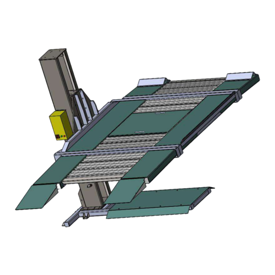
Version 1 CHAPTER 4: DESCRIPTION AND TECHNICAL DATA 4.1 OVERALL DESCRIPTION . Unit Base 2. Cover of base 3. Carriage 4. Post 5. Support beam 6. Platform (3 pcs) 7. Ramp 8. Wave plate 9. Stopper 10. Hydraulic power unit 11. - Page 10 Version 1 4.2 TECHNICAL DATA Manufacturer Strongman Tools Ltd Single Post Car Parking Lift – Hydraulic driven Machine Type Model NO. Telford - Single Post Max Lifting Capacity 2000 Kg Max Lifting Height 1820mm Max dimension of vehicle 5000*1850*1550mm Max weight of vehicle...
- Page 11 4.4 Lift Dimensions Version 1...
-
Page 12: Chapter 5: Installation Instructions
Version 1 CHAPTER 5: INSTALLATION INSTRUCTIONS Strongman Tools Ltd Equipment, ensuring our customers’ safety is our primary concern. Our car parking lift was designed and built with safety. However, safety relies on proper installation and training. Prepare for a successful installation by making sure your floor meets specific requirements. - Page 13 Version 1 5.1 Unpacking the package Check the package and off-load the contents near the installation place. Fig. 7 The hydraulic power unit box and standard parts & chains box are light, could be carried by hand. Then take out steel parts one by one using suitable lifting hoist (Fig. 9 is an example of hoist). Fig.
- Page 14 Version 1 Parts need crane or hoist to carry during off-loading the package for installing the lift Description Weight (kg) Carrying Method Runway platform (at stopper side) Runway platform (at ramp side) Cover of base Post and Carriage By Crane or hoist Base Mid platform Steel plate for packaging...
- Page 15 Version 1 5.3 FLOOR REQUIREMENTS: A leveled floor is strongly suggested for proper installation and balance lifting. Small differences in floor slopes may be compensated by proper shims. If a floor is of questionable slope, consider the possibility of pouring a new level concrete slab. DO NOT install car lift on any asphalt surface or any surface other than concrete.
- Page 16 Version 1 5.6 PARTS LIST: Main Parts list Item Size (mm) Item Size Stop plate 470*100*40 Oil Tank 10 L Base cover 1420*830 Steel wire rope Post 230*290*320 Chain Lh12461 Ramp 600*470 Base plate Gusset plate 1040*745 Hydraulic Cylinder Wave plate 1040*224 Steel wire rope Middle platform...
-
Page 17: Chapter 6: Installation Steps
Version 1 5.7 BEFORE INSTALLATION 1.Identify the packaging components and check for missing parts. Contact Strongman if shortage discovered. 2.Installation, adjusting and testing operations are to be performed by qualified staff only. 3.The lift must be installed on a leveled concrete floor, having minimum thickness of 150 mm and an extension of at least 1500 mm from anchoring points. - Page 18 Version 1 INSTALL THE BASE ON THE FLOOR. Before this step, carry the base by crane or hoist to installation site as it is heavy. 1. Drill each anchor hole in the concrete using a rotary hammer drill. To assure full holding power, do not oversize the hole or allow drill to wobble.
- Page 19 Version 1 Fig.11 Fig.12 6.3: INSTALLATION OF CARRIAGE, CYLINDER & CHAIN INSIDE THE COLUMN (POST): Carry carriage and post by 1. Insert the carriage (Fig 13) into the post from the top of the post (Fig 14). 2. Insert the chain pulley hole to the head of the cylinder. 3.
- Page 20 Version 1 Fig.13 Fig.14 Fig15 Fig16...
- Page 21 Version 1 Fig.17 Fig.18 Fig.19...
- Page 22 Version 1 Top view of post Back view of carriage and cylinder 6.4: INSTALLATION OF THE COLUMN (POST) ON THE BASE: Place the column in its position over the base using proper lifting hoist. 1. Use fixing bolts M18 x 45 to connect the post base to lift base (Fig.20). 2....
- Page 23 Version 1 Fig 21 6.5: INSTALLATION OF THE PLATFORM 1. Lift up the middle platform using proper hoist and Install it to the carriage using bolts M18 x 45. 2. Lift up the left & right platforms separately and fix them with middle one with fixing bolts M20 x 120 (Fig.22, Fig.23, Fig.24 and Fig.25).
- Page 24 Version 1 Fig.24 Fig.25...
- Page 25 Version 1 Lock device in the post Fig.26 Fig.27...
- Page 26 Version 1 Fig 28...
- Page 27 Version 1 6.6: MOUNTING POWER UNIT Fix the power unit to the column with bolts M8 x 30 (Fig 29). Fig.29 6.7: INSTALL HYDRAULIC OIL HOSE AND FILL THE POWER UNIT TANK WITH OIL 1. Connect the oil hose between hydraulic cylinder and hydraulic power unit using integrated fitting.
- Page 28 Version 1 Fig.31 Fig.32 Fig.33 6.8: MOUNTING CONTROL BOX 1. Fix the electric control box on the stand and place the stand far away from any moving parts to avoid injuries. Make sure that the location of the control panel and its stand is suitable to have clear view to the whole lift during lifting up &...
- Page 29 Version 1 3. Fix control panel on the post, and please pay attention control panel should far away from movable parts of lift. Fig.34 6.9: LUBRICATION OF MOVING PARTS 1. Before operation, use proper grease to lubricate the post from inner parts where the sliding blocks are moving to ensure smooth lifting of carriage.
-
Page 30: Chapter 7: Operation Instructions
Version 1 CHAPTER 7: OPERATION INSTRUCTIONS WARNING: DO NOT PLACE ANY VEHICLE ON THE LIFT BEFORE TRIAL OPERATION. TEST THE LIFT UP AND DOWN SEVERAL TIMES TO INSURE LOCK IS WORKING PROPERLY AND AIR IS REMOVED FROM THE CYLINDER. 7.1 BEFORE OPERATION 1. - Page 31 Version 1 Operation box and remote control...
- Page 32 Version 1 OPERATION STEPS OF OPERATION PANEL(CONTROL PANEL)
- Page 33 Version 1 OPERATION STEPS OF REMOTE CONTROL Parking cars: 1. Make sure platform on the ground floor 2. Drive the car on the plat, and pull hand brake before leaving the car.. 3. Press A button(Up) 4. The car will be lifted on the determined height. 5.
-
Page 34: Chapter 8: Maintenance
Version 1 CHAPTER 8: MAINTENANCE Strongman offers warranty as per Limited Warranty Statement included in this manual. The manufacturer will not take any responsibility for improper installation and operation, overload running, improper concrete flooring (that cannot meet the requirements in the manual), normal mechanical abrasion and insufficient maintenance. - Page 35 Version 1 3. MONTHLY MAINTENANCE Check the tightening of all bolts &screws Check hydraulic connections and hoses for leakage and tighten the loose unions, if necessary. Check the greasing and mechanical wear condition of chains, pins, rollers, and sliding blocks of carriage structure and if necessary, replace the damaged parts.
-
Page 36: Chapter 9: Electric & Hydraulic Diagrams
Version 1 CHAPTER 9: ELECTRIC & HYDRAULIC DIAGRAMS ELECTRICAL DIAGRAM (ELECTRIC LOCK RELEASE) 220V, 50Hz, 1Ph... - Page 37 Version 1 CODE NAME CODE NAME RELAY MOTOR PUSH BUTTOM NEUTRAL TIME RELAY RECTIFIER AC RELAY LIMIT SWITCH SOLENOID VALVE TRANSFORMER INDICATING LAMP CIRCUIT BREAKER MAIN SWITCH...
- Page 38 Version 1 HYDRAULIC DIAGRAM...
- Page 39 Version 1 1- Oil Tank 2- Oil Suction Pipe 3- Oil Filter 4- Oil Return Pipe 5- Gear Pump 6- Valve Block 7- One Way Valve 8- Solenoid Valve 9- Hydraulic Motor 10- Throttle Valve...
- Page 40 Version 1 Filter Motor Gear pump Relief valve One-way valve Cylinder Solenoid valve Throttle valve Oil tank...
-
Page 41: Chapter 10: Trouble Shooting
Version 1 CHAPTER 10: TROUBLE SHOOTING TROUBLE CAUSE SOLUTION Pump/ Motor does not start Improper electrical hook up Rewire. Blown Fuse Replace Fuse. Pump binding or stuck Remove (flush) or replace. Motor thermal overload tripped Let Cool 30 sec. Thermal overload in starter box Push Button Reset. - Page 42 Version 1 Platform doesn’t come down Operate to rise up to release the Latch in locking position locking latch before lowering. Check electromagnetic switch which locks/ unlock the latch. Release valve is blocked by Inspect valve and clean or contamination replace Air in oil Loose inlet connection...
-
Page 43: Chapter 11: Limited Warranty
Version 1 CHAPTER 11: LIMITED WARRANTY The user of car lifts is solely responsible for using this equipment safely and considering all of the safety guidelines provided in the User Manual and on the warning labels/signs provided with the lift. Your new car parking lift warranty is two years for structure of the lift against breakage or failure and one year for all electrical, mechanical, and hydraulic components, parts or devices to be free of manufacturing defects both in material and workmanship. -
Page 44: Notes
Version 1 NOTES...
Need help?
Do you have a question about the Telford and is the answer not in the manual?
Questions and answers