
Related Manuals for MuchMoreWater BlueBox 4000 RO

Summary of Contents for MuchMoreWater BlueBox 4000 RO
- Page 1 BlueBox 4000 RO Manual Applies to the Standard and Military version PURE WATER – ANYTIME – ANYWHERE...
- Page 2 BlueBox 4000 RO Production line PURE WATER – ANYTIME – ANYWHERE...
-
Page 3: Table Of Contents
BlueBox 4000 RO CONTENTS Safety regulations _________________________________________________________4 General__________________________________________________________________7 Data ____________________________________________________________________8 General _____________________________________________________________________ 8 Pump _______________________________________________________________________ 8 Electric motor ________________________________________________________________ 8 Purification system ____________________________________________________________ 8 Design and function ______________________________________________________10 General ____________________________________________________________________ 11 Accessories__________________________________________________________________ 13 Function, purification process __________________________________________________ 14 Pump unit __________________________________________________________________ 15... -
Page 4: Safety Regulations
Safety regulations WARNING The water purifier contains ESD sensitive equipment. Repairs to the water purifier’s electrical system must only be carried out by a qualified electrician. Risk of damage to the electrical system. WARNING Do not stand behind/in front of the water purifier when loading. Risk of injury. WARNING Observe the utmost cleanliness when working with the water purifier. - Page 5 WARNING The water that comes out of the red wastewater hose must not be drunk or reused. Serious risk of spread of diseases. WARNING Ethanol is a health and environmental hazard. Carefully follow the safety instruction marked on the packaging. WARNING Ethanol is highly flammable.
- Page 6 The water purifier must be adequately protected in accordance with prevailing weather conditions. The water purifier may not be used at temperatures below 5 °C. For information on dangers of freezing, see section Daily inspection. Avoid placing the water purifier in direct sunlight as excessive heat can affect the electronics in the control cabinet.
-
Page 7: General
General Water purifier osmosis 4000 /T is intended to be used for the purification of polluted water where access to fresh drinking water is in short supply. The equipment consists mainly of: two plastic boxes with lids, containing the purifier and: •... -
Page 8: Data
Data General BlueBox4000, Military version Stores title Make and type Modified PureH2O A/S, BlueBox 4000 Purification capacity 4000 l/h (temperature dependent) Dimensions, box 1(2) 1 200 × 1 155 × 1132 mm Dimensions, box 2(2) 1 200 × 1 155 × 1132 mm Weight, box 1(2) approx. - Page 9 Figure 2. Product label on the electric motor Figure 3. Product label on the pump gear...
-
Page 10: Design And Function
Figure 4. Product label on the control cabinet Figure 5. Individual marking on the inside of the boxes Design and function... -
Page 11: General
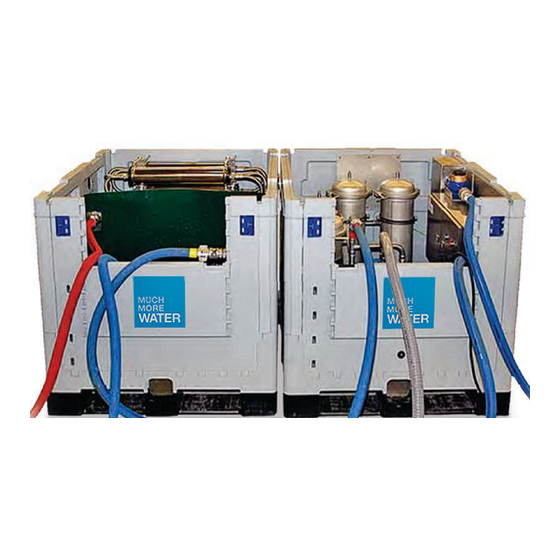
General Water purifier osmosis 4000 /T is mounted in two shock-resistant and weatherproof plastic boxes with removable lids. The boxes are designed so that they can be lifted with pallet forks. Both boxes have dry air supply, drainage at the bottom and hinged doors for easier access to the water purification plant. - Page 12 1 Osmosis unit Hinged door Box 2 Figure 7. Water purifier osmosis 4000, box 2 Figure 8. Dry air connection...
-
Page 13: Accessories
Figure 9. Drainage Accessories The water purifier’s accessories to be stored in box 2. -
Page 14: Function, Purification Process
Function, purification process The pump sucks in water through the floating filter. It is then pumped through the four pre-filters (two particle and two carbon filters) where it is cleansed of particles and organic substances. After the pre-filters the water is led into the osmosis unit, which has three circuits, separated by a membrane. -
Page 15: Pump Unit
Pump unit The pump unit consists of a triple diaphragm pump and a directly connected three- phase electric motor. The pump unit sits on a rubber-mounted frame. The pump is self- priming and does not need to be filled with water before starting. On the pump’s pressure side is a pressure damper. - Page 16 The pump has two lubricator nipples for grease lubrication of the pump journal bearings. One lubricator nipple is to be accessed from the front of the box via a plug in the box. Figure 12. Hole for lubricator nipple The other lubricator nipple is positioned just in front of the cover over the pump shaft. Figure 13.
-
Page 17: Control Cabinet
Control cabinet WARNING The water purifier contains ESD sensitive equipment. Repairs to the water purifier’s electrical system must only be carried out by a qualified electrician. Risk of damage the electrical system. The control cabinet is bolted to the inner wall of box 1. The cabinet has two opening doors. - Page 18 UV purifier’s monitoring panel On the UV purifier’s power supply unit is a monitoring panel. The monitoring panel indicates the operation of the UV lamp using various LEDs, see table 1, page 23. By pressing the reset button A, Figure 18, the alarm signal is temporarily disconnected. The alarm sounds again after seven days.
- Page 19 Table 1. Indicators on UV lamp’s panel Green Yellow Flashing Permanent Normal Fault in power Inactive due to operation supply unit faulty lamp - replace unit - replace lamp Normal The fan is operation disconnected – connect the fan The fan runs too slowly –...
-
Page 20: Purification System
Purification system Floating filter The floating filter sits at one end of the suction hose and has the task of filtering out impurities down to 100 m before the water reaches the pump. The floating filter consists mainly of a steel wire strainer, two plastic grilles and a float. The float must be filled with water to adjust the flow depth. - Page 21 Particle filter 5 Particle filter 5 m consists of a filter container of steel containing a three-insert filter. The particle filter purifies the water of particles down to 5 m. Dirty filter inserts must always be replaced with new. The filter container can be cleaned by rinsing with clean water.
- Page 22 Osmosis unit The water purifier has 12 series-connected reverse osmosis membranes. Each one is mounted in a tube of stainless steel. The osmosis unit is located in box 2. Figure 21. Osmosis unit Reverse osmosis works by pressurising contaminated water and forcing it against synthetic semipermeable membranes.
- Page 23 destroys any ozone. The UV light kills the microorganisms by destroying their DNA/RNA structures. Figure 22. UV purifier Flow meter On the line from the UV purifier’s outlet is a flow meter. The meter shows the amount of clean water, which passes through the system. The meter has a counting mechanism that shows passing water flow in cubic metres and an indicator that on each revolution shows 1 dl.
- Page 24 Pressure control valve On the osmosis unit’s outlet pipe for contaminated water is a pressure control valve. Its task is to create a counterpressure in the system so that the water is forced against the osmosis membranes and purification can take place. Figure 24.
- Page 25 Figure 26. Manometer, pump Hoses For the water purifier there are five hoses. Transparent suction hose, item 4, with a floating filter at one end with a black- • marked female connector for quick connection to the pump at the other. Blue hose, item 2, which is permanently connected to the osmosis unit at the one •...
- Page 26 1 Waste water hose 3 Hose between osmosis unit and UV purifier (yellow marked) 2 Hose between pre-filter and osmosis 4 Suction hose (black marked) unit (red marked) 5 Fresh water hose Figure 27. Hoses Draining valve On the inside of the water purifier’s short side in box 2 is a draining valve. The valve must be in the closed position when the purifier is not in use.
- Page 27 Figure 28. Draining valve, closed position Test outlet The water purifier has two test outlets for checking the water quality. There is one outlet in each box. In box 1 the test outlet is located on the quick connection by the carbon filter. Figure 29.
-
Page 28: Operation
Operation WARNING Do not stand behind/in front of the water purifier when loading. Risk of injury. WARNING Observe the utmost cleanliness when working with the water purifier. Contaminated drinking water involves high risk of transmission of diseases. WARNING It is important that the hoses are not connected to the wrong outlets on the water purifier. -
Page 29: Installation And Connection
Installation and connection Set up both boxed next to each other, with the labelling in the same direction, near the water source to be used. Avoid placing the water purifier in direct sunlight as excessive heat can affect the electronics in the control cabinet. Remove the lid from both boxes and fold down the doors. - Page 30 Connect the black marked suction hose to the pump’s black marked quick connection. Figure 32. Connection of suction hose Remove the red marked blue hose from box 2 and connect it to the red marked quick connection by the carbon filter in box 1. Figure 33.
-
Page 31: Start
Remove the yellow marked blue hose from box 1 and connect it to the yellow marked quick connection inside the door in box 2. Figure 34. Connection of hose between UV lamp and osmosis unit Place the red waste water hose from the osmosis unit in box 2, in the designated outlet. - Page 32 Turn the power switch on the control cabinet to the ON position and start the water purifier by pressing the green START button. 1 START 2 STOP 3 Main switch Figure 36. Control cabinet Loosen the venting screws on the filter containers. Allow the water purifier to run until no more air comes out at the venting screws or in the red wastewater hose in box 2.
-
Page 33: Stop
Carefully turn the pressure control valve in box 2 clockwise until the manometer shows 8–10 bar. Check on the UV purifier’s panel in the control cabinet that the UV lamp is working. During operation, check regularly on the UV purifier’s panel that the UV lamp is working. -
Page 34: Disconnection
Disconnection Remove the power cable from the power supply, clean it and wind it together. Clean, remove and empty all hoses. Roll up the hoses. Open the draining valve and allow all the water to run out. Close the draining valve. Figure 38. -
Page 35: Prior To Short-Term Storage, Danger Of Freezing
Figure 40. Hoses packed in box 2 Pack accessories in box 2. Open the doors on the boxes, fit the lid and slide the locking devices in place. Prior to short-term storage, danger of freezing Clean thoroughly, see section Cleaning, complete, page 42. Open the pre-filter’s container and remove the filter inserts in box 1. - Page 36 WARNING Ethanol is highly flammable. Smoking and the introduction of an open flame must not occur during the handling of Ethanol. Risk of injury. Make a spirit mixture in a clean bowl. The spirit mixture must consist of 11 litres ALCOHOL 95 % and 39 litres of clean water.
-
Page 37: Startup Of Spirit-Filled Water Purifier
10 Place the end of the wastewater hose in the bowl with the spirit mixture. Ensure that the hose cannot fall out of the bowl. 11 Connect the separate hose to the anti-freeze pump’s suction side. Place the free end of the hose in the bowl with the spirits solution. Ensure that the hose cannot fall out of the bowl. -
Page 38: Cleaning With Rocide
Cleaning with RoCide After more than 14 days of standstill and before storing, the BlueBox 1200 must undergo a complete cleaning process. Please ensure that you have approximately 200 litres of clean water available before you start the cleaning process. Cleaning procedure with Sodium Hydroxide and Nitric Acid (For example RoClean P303 and RoClean P111) Remove the filter cartridges from the housings. -
Page 39: Cleaning, Complete
Cleaning, complete Action matrix cleaning and freeze protection Climate/ temp Purifier shut down less Purifier shut down than one week longer than one week Temperate, no frost No special measures Complete cleaning Turn off and restart the Clean the water purifier in water purifier in accordance accordance with section with section Stop, page 38... - Page 40 WARNING A complete cleaning of the water purifier should be carried out once a month and if it has not been used for more than 14 days. WARNING Carefully follow the safety instructions marked on the detergent’s original packaging. The product is highly corrosive. Wear eye protection and protective gloves. Pre-rinse Connect the electric cable and hoses to the water purification container.
-
Page 41: Care
Place the suction hose and both outlet hoses in the bowl with the acid solution. Turn the pressure control valve anticlockwise to the end position. Start the pump and let it run for approx. 10 minutes without pressure. Turn the pressure control valve clockwise until the manometer on the osmosis unit shows 8 bar. -
Page 42: General Maintenance
Daily and special supervision must be carried out in accordance with equipment maintenance schedule. To help you there are instructions in this user manual. Make daily inspections without orders. Be aware that certain measures must be • taken before use, others during and after operation of the equipment. Carry out special supervision on the orders of a responsible officer. - Page 43 Never spray water directly on electrical equipment. Check that: the drainage holes in the bottom of the box are not blocked. • accessories used are cleaned. • Cleaning of floating filter Unscrew the float. Remove the upper plastic grille, wire sieve and lower grille. Carefully clean all parts in clean water with a brush.
- Page 44 Figure 43. Floating filter Cleaning of particle filter 25 Remove the lid on the filter container, loosen the inner holder by pushing it down and twisting simultaneously. Take out the filter bag. Figure 44. Changing the filter bag 25 m Clean the holder and the filter container internally with clean water, then dry with a clean, dry cloth.
-
Page 45: Special Supervision
Special supervision Every 40 hours of operation, but at least every month 1. Particle and carbon filter Comply with applicable waste regulations regarding the handling of used filters. Cleaning of particle filter 25 m Clean particle filter 25 m in accordance with section Cleaning of particle filter 25 m, page 48. - Page 46 Figure 46. Change of filter insert, carbon filter Clean the holder and the filter container internally, as well as the inner lid, with clean water, then dry with a clean, dry cloth. Fit new filter inserts and replace the holder and lid. Check that the lid’s seal is undamaged and is in place, change seal if necessary.
- Page 47 5. Control cabinet Check that: the control cabinet is securely attached and is free from damage • the safety switch can be turned to its two positions • the cabinet’s door can open and close • the door seal is in place and is free from damage. •...
- Page 48 Figure 48. Lubricator nipple, behind the plug No later than every three months 8. Signs and stickers Check that all signs and stickers are hole and readable. 9. Boxes Check that: the boxes and lids are free from damage • the locking devices for holding the lid are securely attached and are free from •...
- Page 49 12. Pump unit Check that: the pump is securely attached to the motor and the unit is free from damage • the pump unit is securely attached to the frame and that the rubber suspensions • are not damaged the pump’s inlet connection is securely attached and is free from damage •...
-
Page 50: Troubleshooting
Troubleshooting Faults Possible cause Proposal for action The pump provides no The floating filter is Clean the floating filter. pressure. blocked. The suction height (max 5 Adjust the suction height. metres) has been exceeded. Contact technician. The pump membranes are faulty. - Page 51 Notes...
- Page 52 PURE WATER – ANYTIME – ANYWHERE Much More Water A/S Staerkendevej 43 DK-4000 Roskilde • phone: +45 8020 8020 info@MuchMoreWater.com www.MuchMoreWater.com...
Need help?
Do you have a question about the BlueBox 4000 RO and is the answer not in the manual?
Questions and answers