Table of Contents
Advertisement
Quick Links
Advertisement
Table of Contents

Related Manuals for Nortek Signature VM


Summary of Contents for Nortek Signature VM
- Page 1 Signature VM Operations Manual N3015-026500 | V 1.1 V 1.4 ````````...
-
Page 2: Table Of Contents
Signature AD2CP Sensor ........................ 7 GNSS Receiver ..........................7 Data acquisition system ........................8 Getting Started ............................9 Checking the Inventory ........................9 Signature VM Software ........................9 Interface ............................9 2.3.1 24VDC Version ..........................9 2.3.2 AC version ..........................10 Connecting the parts ........................ - Page 3 $PNORS1 – Sensor Data ......................42 7.1.5 $PNORCV – Velocity data per Cell ................... 42 7.1.6 $PNORC1 – Velocity data per Cell .................... 42 7.1.7 $PNORBT4 – Speed over ground and depth ................43 7.1.8 $VDVDR – Current Speed and Direction .................. 43 7.1.9 Installation ..............................
- Page 4 Preface This manual is designed to help users of Signature VM to get familiar with the system. The manual includes chapters covering how to get the system up and running as quickly as possible, functional testing, software information, and tips for maintenance and troubleshooting.
- Page 5 Safety when installing and operating the Signature VM Sensor • When mounting the Signature sensor on any vessel or other platform, be careful...
-
Page 6: System Overview
1 System Overview The Signature VM system is a highly integrated system with the sole purpose of accurately measuring vertical profiles of the water’s velocity and direction from a moving platform. Velocity of the water is measured using a Signature series sensor. The Signature sensors are advanced five-beam current profiling systems. -
Page 7: Signature Ad2Cp Sensor
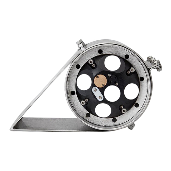
Figure 2 Signature Transducers and sensors Power requirements: DC input: 12-48 (Sig500/1000) For more details on the Signature Sensor itself, please refer to the Signature Manual, as available on the Nortek group website: http://www.nortekgroup.com/manuals-quick-guides 1.2 GNSS Receiver Figure 3 GNSS - Receiver... -
Page 8: Data Acquisition System
Figure 4 Signature VM Data acquisition and interface Data is collected using a computer running the ‘Signature VM’ software. The Signature VM interface box provides all necessary connection and power to the individual instruments. The total system is 19” rack mountable. -
Page 9: Getting Started
2.2 Signature VM Software The Signature VM software is under continuous development, so it is advised to check on a regular basis if a new version is available. Note that a decent internet connection is required for checking and possible downloads. -
Page 10: Ac Version
Ethernet Figure 6 Connecting the interface to the PC Note that only one ethernet port on the PC is configured to connect to the Signature VM Interface. The system will not work if this is connected to the wrong port! The second ethernet port may be connected to the local network and is only used to access the internet. - Page 11 8-pin Serial 6 pin Ethernet + Power (NOT USED) Figure 7 Signature Sensor connections When mating the SubConn connectors pay attention to the following guidelines: Recommended level of grease • Connectors must be greased with Molykote 44 Medium before every mating. A small amount of grease is supplied with the system.
- Page 12 The standard Signature cable comes with a simple jack plug. On the interface that power is supplied through a DC-Power plug with lock-nut. An adapter cable is supplied to connect the standard signature cable to the interface. Lock it by tightening the nut. Figure 8 Signature Power and data connection NORTEK...
-
Page 13: Gnss Connection
2.4.2 GNSS Connection The GNSS is supplied with a 20 m Ethernet cable. One end has a small plastic connector with a bayonet lock which goes to the GNSS unit. When connecting first check the orientation of the Ethernet connector. Then push in while holding the plastic locking-ring. - Page 14 Figure 10 Connecting the GNSS to the interface NORTEK...
-
Page 15: Computer Connections
2.4.3 Computer connections Next to the GNSS connector is the main Ethernet port and a USB port which have to be connected to the Signature VM computer. LAN and USB to computer Power and Data to GNSS Data to Signature... -
Page 16: Power On
Then switch off the interface. 2.4.6 Connecting to the Computer Though it is possible to connect to the Signature VM PC using a keyboard/mouse/monitor, the general idea is to use a remote desktop connection from a laptop. (Not supplied with the system) Any computer that can run the Remote desktop client can be used to connect to the system. - Page 17 Now connect the client computer to the interface, and then open ‘Remote Desktop’ (Hit the ‘Windows’ key, and just type ‘remote desktop’)
- Page 18 User: SurveyVM Passw: SurveyVM The address of the Signature VM PC is fixed to 192.168.100.1. The user name is ‘SurveyVM’. You can now click ‘Save As’ to save this connection for later. Click connect. If all is correct, a popup will appear asking for the password. The password is ‘SurveyVM’...
-
Page 19: Acquisition Software
3 Acquisition Software Once everything is connected, start the Signature VM software. Window recovery buttons Each window may be moved, rescaled or closed if required. To recover a window, or to reset the screen layout to defaults, click on one of the four window recovery buttons in the lower left. Clicking the appropriate button will bring up the related window, or you can click ‘Restore Layout’... - Page 20 Connect / Disconnect the instruments Start/Stop the measurement Instrument connection options Open a file for playback Start / Stop playback Pause playback Playback options Start a new recording Recording details Start NMEA output NMEA output settings Configuration Figure 12 Taskbar explained NORTEK...
-
Page 21: Checking The System
4.1 Checking the system The instrument connection options appear when clicking the ‘three dots’ button in the instruments section of the task bar. Instrument connection options Type: Advanced Navigation. This is the dedicated output format of the Advanced Navigation GNSS. The second option is ‘Network NMEA’... - Page 22 GNSS antenna. The map is only visible if the computer is also connected to the internet. Next select the Nortek Sensor Communication. When the program is started it will automatically search for any Signature Sensors on the network. In general there will be only one, so when the sensor settings appear it will show the serial number of the attached sensor.
- Page 23 ‘Start’ button is available. Figure 15 Signature Connect settings Click ‘Connect’ to start the Nortek sensor. The address / serial number box will turn grey and the button text will change to ‘Disconnect’ and a ‘Start’ button will be available.
- Page 24 The ‘Status’ panel shows a detailed overview of what is received and what is not. Data from GNSS: Position, Heading, Speed and Time Data from Nortek Signature Bottom track: Ship Velocity and depth information Beam Data: Water flow and direction Figure 17 Status panel with status indicators The Position, Heading, Speed and Time are provided by the GNSS.
-
Page 25: Measuring
5 Measuring If everything is configured correctly and working as described in the previous section the measurement may be started. 5.1 Configuration Start by checking the configuration and adjust the necessary variables. Click the ‘Configuration’ button to bring up the settings: Figure 18 Configuration pop-up window Usually most settings can stay at their default. - Page 26 Recorder file location ..\Documents\Nortek\ Where the recorded data is stored. SignatureVM Show time in UTC Off (Local time) Show time and date on the screen in UTC. Does not change the recorded data which is always recorded with UTC timetags.
-
Page 27: Start The Measurement
5.2 Start the measurement When every sensor was checked and found to be working, as described in the previous section, the system can be started by simply clicking the ‘Connect’ button: When the instruments are connected, click the ‘Start measurement’ button. There will be a pop-up window where you can set or verify the main measurement settings: Connected, the button is now set to ‘Disconnect’... - Page 28 This may be useful to start a new file when a specific area or track is started. Click ‘REC’ to start a new recording Recording status will bring up the popup Figure 20 Recording and recording status NORTEK...
-
Page 29: Measuring And Display
5.3 Measuring and Display 5.4 Status Current: Averaged current speed and direction referenced to earth. Vessel Velocity Through Water. Speed and direction of the vessel relative to the water. Bottom Track: Vessel Speed and Direction over Ground as measured by the Signature. Depth: Depth as measured by the central acoustic beam in the Signature Global Navigation Satellite System: Vessel... -
Page 30: Track Display
Note that the background map may only be visible if there is a live internet connection since these maps are loaded form either Bing or Google maps. Clicking the round ‘< ‘ button on the right top of the map opens the map options menu. NORTEK... - Page 31 Figure 24 Track display options When the calculated track starts to drift away from the actual track you can reset it by clicking ‘BT Reset’ or press <Ctrl>-R on the keyboard. ‘Refresh’ will re-center the map. If ‘Automatic Center’ is enabled, the map will automatically shift the ship track to the centre if it gets too close to the edge.
-
Page 32: Echograms
The ‘NUM’ is the numeric value of this error, ‘STR’ is the human readable description and ‘LIM’ are the limits that were exceeded leading to the error. Usually the text will give the user a hint as to where or why the error occurred. The most common error is the following: NORTEK... - Page 33 ‘NUM=9,STR=”PTP clock not synchronized”,LIM=”” This indicates that there is no PTP (Precision Time Protocol) signal present. This signal should come from the GNSS, so this either may not be connected yet, or the GNSS has not locked in to any satellites and therefore has not found the correct time.
-
Page 34: Offsets
SHIP GNSS Signature Figure 27 Vessel coordinate system First there is the ship itself, to which everything should be aligned. The centre axis is the X-Axis, and forward is positive. The angles are right-hand, so positive angles are clockwise. NORTEK... -
Page 35: Horizontal And Vertical Offsets
Second is the GNSS which should be aligned with the vessel centreline, but could be a few degrees off And finally, there is the Signature sensor which by default has 45 degrees offset if installed according to the instructions in ‘Installation’ chapter. It is worth noting that the Signature sensor is essentially mounted ‘upside-down’. - Page 36 In the example the Y offset from the Signature to the GNSS is -3.45 and the X Offset is +1.43. Since the Signature is the reference (point 0,0,0) and we are entering the offsets FROM the Signature TO the GNSS. NORTEK...
-
Page 37: Orientation Of The Gnss And Signature
6.3 Orientation of the GNSS and Signature Next align the ‘Heading’ and the GNSS direction. The heading, measured by the GNSS, is the actual, true north, direction that the antenna is pointing at. The direction as indicated under the ‘Global Navigation Satellite System’... - Page 38 Click ‘BT Reset’ to align direction of the bottomtrack line the bottomtrack line matches the direction of the vessel. with the vessel position When properly aligned, these two directions should match (+/- 1 degree) Don’t forget to click ‘Save Configuration’ ! NORTEK...
-
Page 39: Output
7 Output 7.1 NMEA Output NMEA compatible output is available as UDP messages and may be sent to a user specified IP address and port. To enable NMEA output, first select ‘Use NMEA output channel’ in the Configuration window. Now click the ‘NMEA output settings’... -
Page 40: Sdgga - Global Positioning System Fix Data
Speed over ground in km/h dd.dd Example: $SDVTG,0.00,T,,M,1.85,N,3.60,K*59 The following messages are a subset of the messages as used by the Nortek DVL (Doppler Velocity Log), but the ‘Tagged NMEA’ versions are not supported (e.g. $PNORS2,DATE=083013,TIME=132455,EC=0, SC- 34000034…) 7.1.4 $PNORI1 – General Information... - Page 41 $PNORI1,4,123456,3,30,1.00,5.00,ENU*5B...
-
Page 42: Pnors1 - Sensor Data
Amplitude Beam 3 [dB] ddd.d Amplitude Beam 4 [dB] ddd.d Correlation Beam 1 Correlation Beam 2 Correlation Beam 3 Correlation Beam 4 Example: $PNORCV,201419,112049.21,59,29.7,-2.464,-3.178,0.55,0.396,4.022,217.788,D,33,33.5,33,32.5,12,32,34,21*78 7.1.7 $PNORC1 – Velocity data per Cell Field Description DataFormat Date MMDDYY Time Hhmmss Cell Number NORTEK... -
Page 43: Pnorbt4 - Speed Over Ground And Depth
Cell Position Distance from sensor to centre dd.dd of the cell[m] Velocity East [m/s] dd.ddd Velocity North [m/s] dd.ddd Velocity Up [m/s] dd.ddd Amplitude Beam 1 [dB] ddd.d Amplitude Beam 2 [dB] ddd.d Amplitude Beam 3 [dB] ddd.d Amplitude Beam 4 [dB] ddd.d Correlation Beam 1... -
Page 44: Installation
Signature sensor that will deflect the bubbles. Another possibility, often used with commercial echo sounders, is to mount the Signature sensor on a piston rod that can be moved as much as 0.5-1m below the hull so the sensor head is located below the bubble layer. 8.2.2 Grounding NORTEK... -
Page 45: Ship Movements
When mounting the sensor in a ship’s hull or on another platform, make sure the grounding point always Grounding Point. This should always be submerged ! touches the water. 8.2.3 Ship movements Try to avoid mounting the Signature sensor too close to the bow or to the stern. Instead, the best areas are toward the middle of the ship. -
Page 46: Over The Side Mounting
For maximum flexibility, the top of the container has 8 slots that fit M12 bolts. It is up to the user to provide a mounting structure with a mating flange. The example shows a standard flange, model EN 1092-1. NORTEK... - Page 47 1. Mount the bolts on top of the cylinder and align them with the holes in the flange (A) 2. Route the cable and connect it to the instrument 3. Mount the instrument, using the optional internal clamp (B) and the four bolts (C). 4.
- Page 48 It is not a huge problem if it isn’t completely aligned but the closer the better. The GNSS antenna comes with a stainless-steel Mast/Rail bracket that can be clamped to a horizontal or vertical pole as shown in the figure below. NORTEK...
- Page 49 To attach the antenna to the mounting pole, first put the nut and the plastic ring on the thread, then screw on the antenna. Point the antenna so it is in line with the ship’s main axis and fix it in position using the nut. Figure 32 Mechanical drawing of GNSS Compass Figure 33 GNSS Ethernet Cable...
-
Page 50: Maintenance
9.3 Instrument Care All Nortek instruments are intended for use in water. Other fluids may have an adverse effect on the plastic materials used. For prolonged storage at elevated temperatures close to the specified limit, or when temperature variation is uncertain, it is recommended that the screws securing the end cap be loosened in order to minimize the risk of any deformation due to temperature/stress over time. -
Page 51: Connector Care
If the instrument has been subjected to environmental conditions outside the specified design limits (refer to the instrument brochure for specifications) mechanical tolerances may be affected. 9.4 Connector Care It is extremely important to keep connectors clean and well lubricated. Before plugging in connectors we recommend to always blast the pins with compressed air, inspect them for cleanliness and then protect the cable connector by applying a thin layer of silicone grease. -
Page 52: Troubleshooting
In general, every Signature VM computer comes with the TeamViewer software. This allows the user to give a Nortek support engineer access to the computer so he or she can check what might be wrong with your software or configuration. Make sure you have a working internet connection, and when requested by the Nortek engineer, click the TeamViewer icon to start a session. -
Page 53: Communication
When the program has started successfully, and the ‘Ready to connect’ message is visible no further action is necessary. The Nortek engineer can now connect to your computer and try to solve your problem. 10.2 Communication The blue LED indicator light on the instrument is not lit •... -
Page 54: Computer Configuration
168.100.1 to 192-168.100.254 OpenDHCP was added to the Windows firewall as an allowed application. Both the Signature Sensor and the GNSS are set to ‘DHCP’ so they will get an address from the computer when connected to the ‘SurveyVM Interface’. NORTEK... - Page 55 Remote Desktop is enabled, and this is explicitly bound to the 192.168.100.1 address, so it will only work if a computer is connected directly (or through a switch) to the ‘SurveyVM Interface’ port. Remote desktop is not possible over the ‘Ethernet’ port.
-
Page 56: Gnss
The Advanced Navigation GNSS can receive external correction signals over the Ethernet link using a protocol named ‘NTRIP’ (Networked Transport of RTCM via Internet Protocol). The GNSS has a built-in NTRIP client that can be configured through the menu. NORTEK... - Page 57 NTRIP data is supplied by several different providers. Usually it’s a local, commercial service of a company that maintains the local network of reference stations. The use of the NTRIP client requires that the system is connected to the internet. To test if it is working, use the server at ‘www.rtk2go.com’, port 2101 as shown in the example above.
-
Page 58: Glossary
Correlation Nominal correlation is a function of cell size and velocity range. Nortek (nominal) recommends using 50% of the max correlation as a cut-off value, beyond this point the validity of your data is questionable. - Page 59 Firmware Internal software of the instrument, as opposed to the instrument software running on a PC. New firmware is posted on the Nortek site. You will need to register to get access, but access is otherwise free of charge. Ice Draft (keel) Measures thickness of ice.
-
Page 60: Connector Pin Configurations
9-pin DSUB Tx / Female face view RS422 RS422 Blue White RS232 Rx White Orange / RS422 RS422 Orange Purple White Shield Green *) GND on pin 1 on instrument side, pin 5 on DSUB and on Jack Plug (jacket) NORTEK...
Need help?
Do you have a question about the Signature VM and is the answer not in the manual?
Questions and answers