Table of Contents
Advertisement
Quick Links
Advertisement
Table of Contents

Related Manuals for Nortek Vector


Summary of Contents for Nortek Vector
-
Page 2: Table Of Contents
Configuring a Vector 2.1.4 ................................27 Data Collection 2.1.5 ................................28 Mounting and Handling the Probe 2.1.6 ................................29 Orientation of Vector probes 2.1.7 ................................30 Measuring Waves 2.1.8 ................................31 Processing Method Wave Parameters Deployment Considerations and Cautionary Notes... - Page 3 Near Boundary Measurements 2.5.6 ................................57 ........................57 Common Configuration Scenarios ........................59 Quality Assurance of Velocimeter Data ........................60 Common Data Analysis Scenarios Chapter 3 Service Manual ........................63 Function Testing Initial Test Setup 3.1.1 ................................63 © 2018 Nortek AS...
- Page 4 3.3.4 ................................76 Installing IMU sensor (Vector) 3.3.5 ................................76 Changing the Wiring Harness (Vector) 3.3.6 ................................77 Changing the Output Power for Auxiliary Sensors (Vector) 3.3.7 ................................77 Midlife Electronics Pre-midlife Electronics ........................79 Changing a Probe ........................79 Upgrade Firmware ........................
- Page 5 Serial COM port 5.1.5 ................................103 Break Response 5.1.6 ................................103 Loop Back Test 5.1.7 ................................104 5.1.8 Test with both RS422 and RS232 communication (Vector) ................................105 Software 5.1.9 ................................105 Check Current Drain 5.1.10 ................................105 © 2018 Nortek AS...
- Page 6 5.3.6 ................................113 Phase Wrapping 5.3.7 ................................113 Mooring/mounting Vibrations 5.3.8 ................................114 Error and Status Codes (Vector) 5.3.9 ................................115 ........................117 Returning Instruments for Repair ........................118 Appendix A - Final Test Checklist ........................119 Appendix B - Example of Proforma Invoice...
-
Page 7: Chapter 1 Principles Of Operation
Velocimetry is the measurement of the velocity of fluids. The name "Velocimeters" belong to a special class of high-resolution 3D instruments, that comprises the following instruments: The Vector is a field instrument designed for measurements of rapid small scale changes in 3D velocity, used for turbulence, boundary layer measurements, surf zone measurements, and measurements in very low flow areas. -
Page 8: Working Principle
Comprehensive Manual Working Principle The Nortek instruments measure the velocity of water by utilizing a physical principle called the Doppler Effect. The Doppler Effect is the change in frequency of a sound wave when a wave source moves with respect to an observer, or when the observer itself moves relative to the wave source. - Page 9 The reflecting particle can be seen in green, w ith a vector indicating its speed and direction The phase difference between the two reflected pulses is a direct measure of the velocity, and can be expressed as Here, V is the current velocity, ∆φ...
-
Page 10: Doppler Beams
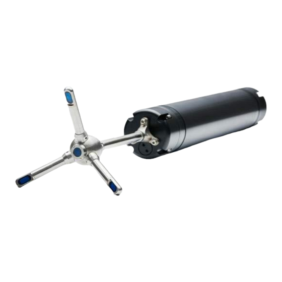
Figure: The blue arrow indicates a positive velocity. The Vector, which is shown in the figure above has three receiver arms, while the Vectrino and the Vectrino Profiler have four receiver arms. Because of the arrangement of the receiver arms, each pair (composed of two opposing receivers) can measure the horizontal velocity component and the vertical velocity component. -
Page 11: Measuring Currents
The user can specify which coordinate system to present the velocity data in. The raw velocity measurement is a vector in the direction along each of the three or four beams, which is referred to as beam coordinates. Beam coordinates can be converted to a Cartesian coordinate system (XYZ) by knowing the beam orientation. -
Page 12: Auxiliary Sensors
(phase wrapping) and higher order turbulence calculations, as these are the "rawest" format. Along with determining a phase shift (and then the velocity vector), the instrument will also typically compute the speed of sound, measure the return signal strength, and measure the attitude sensors such as pitch, roll, and compass heading (if equipped). -
Page 13: Measurement Volume
The simple configuration allows one to basically record motion data simultaneously with the Vector velocity data. Physically, the IMU is incorporated in the Vector by simply using the magnetometer contact interface. This means the standard tilt and magnetometer are removed and replaced with the IMU, so there is no standard Nortek compass system with the IMU integrated. -
Page 14: Vectrino
With a profiling range up to 30 mm, a usable profiling region approximately 40-70 mm in height from the central transducer is provided. The Vectrino Profiler pulse intervals are longer than the Vectrino because of the need to sample data from farther away. © 2018 Nortek AS... -
Page 15: Coordinate System
You may specify the preferred coordinate system in the Deployment Planning menu of the instrument specific software. The velocity measurement is a vector in the direction of the transducer beam, which we refer to as beam coordinates. Beam coordinates can be converted to a Cartesian coordinate system (XYZ) by knowing the beam orientation. -
Page 16: Signal Strength
Beam 1 of the Vectrino has a red m arking, a black m arking defines beam 1 for the Vector (not show n here). For the Vector, beam 1 is also the arm opposite of the engraved head ID. -
Page 17: Correlation
For users interested in sediment concentration estimates it is recommended to take a look at this subject in the Frequently Asked Questions (FAQ) on the Nortek web. Figure: Signal to Noise Ratio from one Vectrino Profiler beam . A fixed boundary can be seen at about 6cm... -
Page 18: Distance Measurement / Bottom Check
Profiler, but not in the Vectrino standard firmware. Vector: The Vector reports the distance to the boundary at the start and end of each burst, or at the start when running the instrument in Continuous mode. That means that it is possible to do very short bursts and get almost simultaneous measurements (requires Firmware V1.20 or higher). -
Page 19: Velocimeter Accuracy
We provide all of the data used to determine the peak location if users need to create their own bottom detection algorithm. This is available as the probe check data in the Vector and Vectrino, and in the Bottom Check fields in the Vectrino Profiler data structure. - Page 20 By decreasing the measurement load it is the other way around. The measurement load for the Vector is adjusted according to the velocity range selected. Variance and Noise Level © 2018 Nortek AS...
- Page 21 Here is how the noise level and measurement variance are related: variance = (noise level)*(sample rate)/2 By using the equation in the "Averaging" section, the equation above can be turned into an equation for standard deviation. © 2018 Nortek AS...
-
Page 22: Chapter 2 Using A Velocimeter
Comprehensive Manual Using a Velocimeter This section covers What you need to know when using a Vector What you need to know when using a Vectrino and/or a Vectrino Plus What you need to know when using a Vectrino Profiler... -
Page 23: Vector
The pressure sensor is not calibrated to, or corrected by the atmospheric pressure. This means that the pressure sensor reading will follow the atmospheric pressure. Therefore, a pressure offset should be run before using the instrument, and this can be done using the Vector software; click Menu: 'On- line' - 'Set Pressure Offset...'. - Page 24 Tilt data is sampled at 1 Hz. The measurement range is +/- 30 degrees. Is there uncertainty about whether the Vector has a vertical or horizontal tilt sensor? If the tilt (pitch and/or roll) as indicated in the Sensors’ pane is unrealistically far from 0° when placing the canister (upright or lying down) on a table, the Vector is of the other type.
-
Page 25: Instrument Software
Nortek. Nortek alkaline battery packs use 18 AA cell batteries at a nominal starting voltage of 13.5 VDC. The voltage of alkaline batteries falls quickly at the beginning, slowly during most of its life, then again quickly at the end. -
Page 26: Initial Preparation
If you remove power and reapply it, the Vector will re-awake with the new baud rate. Note! If data download is interrupted, the Vector may be left with a baud rate setting other than the one used for normal communication. When the software tries to establish communication in such cases, it may spend a few moments searching for the correct baud rate to use. -
Page 27: Configuring A Vector
9. For stand alone systems, it is vital to remember to connect the dummy plug to protect the connectors. 2.1.4 Configuring a Vector The Deployment Planning dialog contains all parameters required to specify the operation of the instrument. The Deployment Planning frame on the right hand of the dialog displays performance parameters that are automatically updated as you change the parameter settings. -
Page 28: Data Collection
7 m/s 125 Hz Example: If the Vector is configured with a 1 m/s velocity range, it has an internal sampling rate of 125 Hz. Each Vector measurement interval uses all of the available samples. If the Sampling rate is set to 64 Hz, then most of the output records will be averages of 2 samples, but a few will have only one sample (125/64 = 1.95). -
Page 29: Mounting And Handling The Probe
You may then set up the Vector to record a copy of all data acquired to the internal recorder, in addition to have the data transferred to the remote computer. This is called Recorder Data Collection, as opposed to Deployment (see buttons in the Vector software). -
Page 30: Orientation Of Vector Probes
For the cable probe, it is critical that during data collection in ENU coordinates, the “X” receiver arm (marked with red) is aligned with the “X” mark on the Vector housing. This is because the compass and tilt sensor is located in the Vector housing. The internal tilt sensor determines up or down, and ultimately ensures that the correct coordinate system is used for the directional estimates. -
Page 31: Measuring Waves
For the cabled type, it is critical that during deployment the instrument’s array relative to its body (cylinder) is the same as it is with the Vector with the stem. This is because the internal tilt sensor determines up or down, and ultimately ensures that the correct coordinate system is used for the directional estimates. -
Page 32: Processing Method
The PUV analysis provides an accurate estimate of the wave elevation spectra in addition to the direction and the directional spreading. The dynamic pressure measurement provides a means of estimating all the non-directional wave parameters, while the combined P, U, and V measurements allow for estimating the directional wave parameters. © 2018 Nortek AS... -
Page 33: Wave Parameters
Amongst the problems are the errors in the calculation of moments and cutting off peaks at higher frequency. One scenario is that an instrument placed in 15 meters of water may never detect the energy up above 0.25 Hz. © 2018 Nortek AS... -
Page 34: Corrections, Measurement Errors And Uncertainties
For tips on how to configure the Vector for wave measurements, check out the "Setting up for operation"... -
Page 35: Optional Imu
The velocity measurements and the IMU data will be presented in the coordinate system selected. The IMU can be used as an AHRS; since the Vector with IMU can be used in any orientation (horizontally, vertically,..) while simultaneously converting the measured velocities to ENU, - thus a full 3D solution. -
Page 36: Data Handling
Data handling Data The Vector creates binary files (*.vec), which can be converted to ASCII format files by using the Data Conversion tool within the Vector software. The Vector records the following: The *.hdr file is a self-documented table. Please note that this file contains the detailed data format of all the other ASCII files. -
Page 37: Vectrino
The Vectrino is shipped with a 12-pin cable and waterproof connector. The Vectrino power lines are diode protected, hence, you do not have to worry about wiring the Vectrino power backwards. If you do, it will not damage your instrument. The pinout is shown in the Service Manual. © 2018 Nortek AS... -
Page 38: Instrument Software
1. Insert the Flash disk 2. Follow the on-screen instructions. Accept the default settings. The Setup program will by default install the application in the c:\Nortek\Vectrino folder and create an application shortcut in the Nortek programs folder and on the desktop. -
Page 39: Configuring A Vectrino
(i.e. the Nyquist sampling criteria). You will need to make a few estimates of what time scales and processes are of interest and select a sample rate appropriate for those. © 2018 Nortek AS... - Page 40 High. Take a look at the Probe Check section for a couple of examples on how to determine whether the power level should be increased or decreased from the default setting. © 2018 Nortek AS...
-
Page 41: Mounting And Handling The Probe
The *.dat file contains velocity data at the full sample rate. The *.pck contains the probe check data ASCII files are easily imported into most spreadsheets and data analysis programs. QA/QC © 2018 Nortek AS... - Page 42 Comprehensive Manual Check the Looking at Velocimeter Data section. Typical processing tasks: 1. Assess data quality (QA/QC) 2. Data screening 3. Statistics to describe the flow (mean, variance) 4. Spectral Analysis (turbulence, waves) © 2018 Nortek AS...
-
Page 43: Vectrino Profiler
Cable wiring: The Vectrino Profiler is shipped with a 12-pin connector and communication cable. The connector type is an MCBH-12-FS waterproof connector. The pin out and wiring of the cable can be found in the Wiring of Cable chapter. © 2018 Nortek AS... -
Page 44: Instrument Software
(run status, collection status, connection status, and instrument status). Hovering the mouse over each status light will display more detailed information. For more detailed information using the software, check the SW User Guide, available under "Help". © 2018 Nortek AS... -
Page 45: Initial Preparation
The corresponding horizontal and vertical ambiguity velocities are displayed (assuming the probe is facing down). The vertical ambiguity velocity corresponds quite closely to the beam velocity. For point measurement instruments, the measured region starts at Range to first cell mm and is of © 2018 Nortek AS... -
Page 46: Mounting And Handling The Probe
Matlab: The .mat file contains Data and Config structured arrays. Each array contains a "Comments" and "Units" field that describe the contents of each structure. ASCII: The .hdr file is a self-documented table The .dat file contains velocity data at the full sample rate © 2018 Nortek AS... -
Page 47: Things To Consider
Vector: The probe check data is available in two ways: Before and after each burst a probe check is made, or at the beginning of the measurement when selecting Continuous mode. Continuous probe check can be gathered if the recording to disk function is enabled before starting a probe check in the Vector software (Online >... - Page 48 Comprehensive Manual Vector and Vectrino: Note the am plitude at the beginning of the sam pling volum e (A), the nice gaussian peak that indicates the sam pling volum e (B) and the peak corresponding to the bottom (C). Also note that the signal strength decrease to the noise floor betw een the m easurem ent volum e and the bottom , and that all colored graphs show roughly the sam e am plitude and profile shape.
-
Page 49: Distance Check
These ranges are presented in the deployment planning dialog (right part). Measurement uncertainty is roughly proportional to the Nominal Velocity Range – smaller velocity © 2018 Nortek AS... -
Page 50: Extended Velocity Range
2.4.5 Weak Spots The Vector, Vectrino and Vectrino Profiler transmits two pings, and as such, they are susceptible to pulse interference when measuring near boundaries. This especially applies to Vectrino Profiler, as this is a profiling instrument and the pulse is in the measurement volume for a longer period of time. - Page 51 0.02, 0.04 Table: Weak spots listed as the distance from Sam ple Volum e to boundary for the Vector and Vectrino. Note that the w eak spot location is dependent on the speed of sound and the boundary surface, so the values given are only estim ates and w eak spots m ay be encountered a centim eter or m ore aw ay from these values.
-
Page 52: Interference From Highly Reflective Bottoms
10 kHz, and can be integrated with the Nortek Vector. By measuring the acceleration, the tilt and the heading, one can correlate vortex induced vibrations with the sampled current velocities, and during post-processing the measured sensor motions can be removed from the velocity data. -
Page 53: Incorrect Speed Of Sound
Vector: Typical moorings allow the instrument to tilt and rotate freely. The Vector measure tilt and heading and uses this compass information to convert the data to true earth coordinates. How often the instrument reads the tilt and heading depends on the deployment method used. -
Page 54: Low Flow Measurements
2.5.4 Laboratory environments Follow these guidelines when you mount your instrument in a lab: Make sure that there are no obstructions between the sensor and the focal point (sampling © 2018 Nortek AS... -
Page 55: Wave Measurements
For the cabled type, it is critical that during deployment the instrument’s array relative to its body (cylinder) is the same as it is with the Vector with the stem. This is because the internal tilt sensor determines up or down, and ultimately ensures that the correct coordinate system is used for the directional estimates. - Page 56 Choosing the best setting is often used in conjunction with the number of samples. The Vector can sample at 1, 2, 4, 8 Hz, etc. However, note that if one is only interested in measuring waves then it is probably not necessary to sample any higher than 2 Hz.
-
Page 57: Near Boundary Measurements
The middle of the sampling volume is positioned approximately 5 cm (or 10 cm on the field probe) below the transmit transducer located at the center of the probe for the Vectrino. For the Vector it is 15 cm, and the measurement volume for the Vectrino Profiler spans from 4-7 cm from the probe (user selectable). - Page 58 If there are any signs of damage to your instrument, such as a bent receiver arm, a bent probe stem for rigid probes, a damaged cable for cabled probes, or damage at the bulkhead connector on either end of the electronics case, please check the Troubleshooting Guide for further suggestions. © 2018 Nortek AS...
-
Page 59: Quality Assurance Of Velocimeter Data
These events usually occur during the deployment, retrieval, and the occasional curious mariner. Data collected during these events should be avoided in the post processing. If the Vector sample volume is out of the water there is no way to recover velocity data. Data during these periods should fail most data quality checks since the SNR will fall to (near) zero. -
Page 60: Common Data Analysis Scenarios
The data may still usable, but if using the Vector one has to process the data with the two other beams only; a solution that is known as a two-beam calculation. This will result in 2D currents only (since there is only data from two beams available. - Page 61 Typical vibrations from instrument mountings will have a very sharp peak and occur for a very narrow frequency band. Vector fixed stem probes will for example often see a peak around 20 Hz. The impact on measurements will depend on what flow parameters are of interest.
-
Page 62: Chapter 3 Service Manual
Please use this Service Manual as guidance and contact us for further assistance. For Vector users: In this manual, you may encounter a couple of unfamiliar terms: Midlife and Pre- Midlife. The difference between the two is simply when the instrument was produced; pre-midlife are instruments produced before 2009. -
Page 63: Function Testing
The internal battery pack is located inside the pressure case. Nortek alkaline battery packs use 18 AA cell batteries at a nominal starting voltage of 13.5 VDC. Note that the battery pack inside the pressure case is disconnected when sent from Nortek. Refer to Changing a battery pack section for instructions on how to connect or change a battery pack. -
Page 64: Connect Cables
We recommend the 3M Silicone Spray. Grease is not recommended. For Vector users: Remember to protect unused connectors with dummy plugs (relevant for Vectors). For more information about how to protect the connectors, check out the Connector Care section. -
Page 65: Temperature
The standard instrument is designed for vertical orientation. That means that you should make sure the Vector canister is in an upright position. The tilt sensor detects up/down orientation - that means that you can use the Vector pointing up or down and the instrument will know. -
Page 66: Compass (Vector)
UP orientation when the communication cable end of the canister is on the top of the canister, ie when the probe is pointing down (as in the figure above). Be aware that when the Vector is running in Continuous mode, the Vector needs to be oriented in the correct orientation when starting it – up/ down orientation will not be updated while measuring. -
Page 67: Pressure (Vector)
First, check the noise level of the instrument. See the readings in the software, under the Current tab. Pinging in air should produce signal strengths (amplitudes) of 45-55 counts for Vector 50 counts for the Vectrino and the Vectrino Profiler When the instrument pings in air, the velocity measurements will be the noise floor. -
Page 68: Beam Amplitude And Velocity Checks
Read more about coordinate systems in the Principles of Operation, where you will find Beam, XYZ, and ENU definitions. Note that the X-axis engraved or clarified in form of a colored indicator on the head/probe of the instrument always points in the direction of beam 1 and a positive X-axis. © 2018 Nortek AS... -
Page 69: Probe Check
Figure: The probe check function show s how the signal varies w ith range. The three colored graphs correspond to each of the three vector receive beam s. A is the transm it pulse. B is the area around the m easurem ent volum e. -
Page 70: Test Recorder Function (Vector)
When it leaves the factory, each system can measure its tilt and the direction of its magnetic field vector accurately, anywhere in the world. However, users disturb the magnetic field near the instrument when they deploy. Adding a battery pack and mounting the instrument with deployment hardware adds magnetic materials that change the magnetic field measured by the instrument. -
Page 71: Set Pressure Offset (Vector)
3.2.2 Set Pressure Offset (Vector) The pressure sensor offset is not calibrated to, nor corrected by the atmospheric pressure. This means that the pressure sensor reading will follow the atmospheric pressure, thus the sensor signal may have an offset. - Page 72 3) When the pressure has a stable reading, as in the screenshot below, click Done. Figure: Set Pressure Offset dialog Figure: Stable pressure reading and the title indicates success © 2018 Nortek AS...
-
Page 73: Working Inside An Instrument
3.3.1 Changing a Battery Pack (Vector) The following procedure outlines how to connect the battery or to install a new battery. A fresh desiccant bag should be included in the pressure case, as humid air can condense enough water do damage the electrical circuitry. -
Page 74: Installing A Memory Board (Vector)
Read also about Recommended Torque for securing screws. 3.3.3 Installing a Memory Board (Vector) When ordering a memory upgrade from Nortek you will receive the following: 1. Recorder / ProLog 2. Screws / Bolts 3. Standoffs 4. Nuts 5. Lock Washers... -
Page 75: Installing A Memory Board - Pre-Midlife (Vector)
3.3.3.1 Installing a Memory Board - Pre-midlife (Vector) When ordering a memory upgrade from Nortek you will receive the following: 1. Long nylon screws 2. Mounting blocks 3. Short nylon screws 4. -
Page 76: Installing A Memory Board With Cable - Really Old Paradopps
3.3.5 Installing IMU sensor (Vector) When ordering an IMU upgrade from Nortek you will receive the a small electronics board that needs to be mounted on the main PCB. It will physically replace the existing compass board Access the circuit board B. -
Page 77: Changing The Wiring Harness (Vector)
G. Carefully insert the system back into the housing. 3.3.7 Changing the Output Power for Auxiliary Sensors (Vector) You can change the output voltage level that is supplied to external sensors. This is typically needed if an external analog sensor (e.g. OBS) operates in a specific voltage range and the raw battery power does not fall within this range. -
Page 78: Midlife Electronics
This can be changed to +5V or to +12V by changing the position of a 0-W resistor. The three resistor positions share one pad so the modification should be straightforward. Voltage level Resistor position Max current R270 (default) 500 mA R268 200 mA +12V R269 50 mA © 2018 Nortek AS... -
Page 79: Changing A Probe
However, new functionality (and in rare cases bug fixes) is likely to be offered in the future, requiring that the firmware is upgraded. New firmware is posted at the Nortek web. You will need to register to get access, but access is quick and free of charge. -
Page 80: Erase Recorder (Vector)
The flash circuit on the main PCB is closely linked to the recorder. Read more about that here. Update Headfile (Vector) Most of the sensors in a Nortek instrument have to be calibrated to keep the specified accuracy. This and the fact that we offer flexibility in probe geometry, deployment orientation and external output/inputs make it necessary to store a number of parameters to make the instrument perform as intended. -
Page 81: Mechanical Aspects And Maintenance
3.8.2 Instrument Care The Nortek instruments are intended for use in water. Other fluids may have an adverse effect on the plastic materials used. If using the Vectrino/Vectrino Profiler lab probes in saline water, it is recommended to keep the deployment time short and to clean the probe with clean water after the deployment. -
Page 82: Recommended Torque For Securing Screws
Do not pull on the cable to disconnect connectors, pull the connector itself. Avoid sharp bends at cable entry to connector. Ensure that the cable is fixed to the mounting fixture to avoid mechanical stress to the connection. © 2018 Nortek AS... -
Page 83: O-Ring Care
We also recommend staying away from strong organic solvents such as acetone. A common, easy, and inexpensive way to keep the Delrin housing on the Vector clean is to wrap the housing in either clear packaging tape and/or clear plastic wrap (such as the brand name "Seran Wrap"). -
Page 84: Cables And Wires
In addition there is a table below describing the harness and the 24 pin connector at the electronics board. This might be handy if there is need to change the wiring harness without time to receive one from Nortek. 3.9.1... - Page 85 Black Wire Twisted White/ Pair Sync. In Green Wire Purple Black Power Gnd Black Wire Twisted Pair White Power + Red Wire Screen terminated at pin 1 in underwater connector, unterminated at PC side. Ref: N2100-108 © 2018 Nortek AS...
- Page 86 Yellow Wire Orange Black Power Gnd Twisted Pair Black Wire White Power + White Wire Bare Ground 3 bare wires for grounds, connected internally to power ground. Ref: N2100-004 *Optional version outputs pressure instead of Z-Velocity © 2018 Nortek AS...
-
Page 87: Vectrino
DSUB, pin 5 White/Orange DSUB, pin 2 White/Red DSUB, pin 3 White/Brown Power - Power supply connector Black/red Power + (12-48V) Power supply connector Ref: N2100-303 Figure: Vectrino connector and draw ing highlighting the pin num bering © 2018 Nortek AS... -
Page 88: Vectrino Profiler
If you want to run a longer cable, you can switch to RS422 by installing a different wiring harness you can get from Nortek. You can also try using RS232 with longer cables by reducing the baud rate. Keep in mind that RS422 is a more reliable means of communication than RS232 –... - Page 89 Analog In 1 Analog In 2 RS422 Tx+ RS422 Tx- RS422 Rx+ RS422 Rx- Sync Out Sync In +3.3V LP RS422 3.3V Supply (grounded for RS232, shorted to pin 23 for RS422) Relevant for Vectors only © 2018 Nortek AS...
-
Page 90: Chapter 4 Integrators Guide - Light
Analog Outputs - relevant for the Vector and the Vectrino Synchronization - relevant for all the velocimeters This chapter cover the subject on how to use Nortek instruments together with other instruments or sensors. For a more comprehensive Integrators Guide, check out the one we have available here: https://www. -
Page 91: Analog Inputs (Vector)
There is an option to connect external sensors to the two analog inputs. The external sensors may be powered by the Vector (enable this in the Deployment Planning dialog), and their data output may be stored in the instrument during a deployment or downloaded in real time. With two external sensors connected, the Vector is able to read both analog inputs at the same time. -
Page 92: Analog Outputs
3 velocities are default. In both the Vector and the Vectrino, the scaling output for the velocities is chosen in the deployment planning. It is important to select an analog range that matches the velocity range. You could in principle use an analog range of +/-7 m/s and a velocity range of +/- 1 m/s, but you would lose a lot of precision. -
Page 93: Vector
A special head configuration file where analog outputs is enabled is needed. Enable analog outputs in the Vector software's planning menu (Advanced Tab). The planning module controls data collection in the Vector the same, whether or not the analog outputs are enabled. -
Page 94: Synchronizing With Other Instruments
Example: If the signal on the SyncIn input to the Vector is generated to correspond to a sampling rate of 25 Hz, the Vector should be configured in software for a sampling rate of 32 Hz. In most cases, it will be sufficient to synchronize different Vectors using Start on Sync. - Page 95 1 Hz output of the system data. Each Vector will then output its system data based on its internal real time clock. This implies that the number of system data outputs may vary slightly from one instrument to another. Note that this is not a problem for the synchronization of the velocity measurements.
- Page 96 (Start on sync and Sample on sync). With the rest of the setup identical for the three instruments; start the two Vector slaves first. When the master Vector then is started, it will trigger the start of the other two Vectors.
-
Page 97: Vectrino
The controller can serve as a storage device. Note: A Vectrino can operate as a master for a Vector, but the opposite is not possible. The Vectrino can be synchronized with other instruments via a pair of sync lines. To avoid noise problems and to make cabling easier, the two sync lines are RS485 which is balanced and bi- directional. -
Page 98: Vectrino Profiler
Configure the Vectrino with the desired velocity range, 30 Hz sampling rate and select output sync for Vectrino and check the box for master Configure the Vector with the desired velocity range, continuous sampling, the next higher available sample rate (so 32 Hz in this example) and check the boxes for start on... - Page 99 Noise problems: If you encounter noise problems, try terminating the Sync- line at the TTL input by connecting a 120 ohm resistor in series with a 1nF capacitor between the Sync- line and the ground. The best solution for external sync is using RS485 as the input/output device. © 2018 Nortek AS...
-
Page 100: Chapter 5 Troubleshooting Guide
If you still have problems after consulting this guide, please contact our subsidiaries, sales representatives or Nortek Support. To help us in giving good support, please be specific about the error – a screen shot is often helpful... -
Page 101: Communication Problems
Do a visual inspection of the power supply. Is a green power light on? Measure the power supply and make sure it is stable Do not exceed the maximum VDC listed in the technical specifications Remember that Nortek instruments ship without the batteries connected 5.1.2 Cable Test Inspect the instrument communication cable for damage such as knicks, cuts, or crushed sections. -
Page 102: Serial-To-Usb Converter
For the standard Vectrino program, the default baud rate is 19200. For Vectrino Plus, the default baud rate is 57600. For the Vector, the default is 9600 For the Vectrino Profiler, 937500 is recommended. A higher baud rate may reduce the download time, but note that the baud rate is limited by the operating system used, the serial port on the computer, and the length of the USB cable. -
Page 103: Serial Com Port
(AquaPro example below): @@@@@@ VECTOR NORTEK 2012 Version 3.43 Command mode ¶¶ Other responses: 1.@@@@@@K1W%!Q@@@@@@K1W%!Q Suggestion: Check that you are using the correct cable (with correct communication - RS232 or RS422) 2..© 2018 Nortek AS... -
Page 104: Loop Back Test
The same principle applies to RS422, except RX+/TX+ and RX-/TX- must be short-circuited - re- spectively pin 8/3 and 7/4. This will be the same on the DSUB as for RS232, since that is after the signal is converted. Figure: 8-pin connector © 2018 Nortek AS... -
Page 105: Test With Both Rs422 And Rs232 Communication (Vector)
Test with both RS422 and RS232 communication (Vector) The Vector is able to communicate at both RS232 and RS422. When not able to communicate with the option installed it could be a good idea to try the different alternative. To do this you will need both cable and harness wired for this communication. -
Page 106: Check Led Indications
The message "Error: Flash Corrupt (I)" may appear in a couple of scenarios in the Terminal Emulator. Vector: The flash corrupt message indicates a problem with the part of the recorder flash where internal parameters are stored such as baud rate, instrument mode etc. The corrective action is to try to erase the recorder and see if the problem disappears. -
Page 107: Calibration Matrix Not Stored
5.2.1 Power Vector: The software allows you to calculate the anticipated power consumption as a function of the sampling scheme and planned deployment duration. The predicted power consumption is given in percentage, where 100% signifies complete depletion of a chosen battery pack for the particular instrument. -
Page 108: Suspicious Data
Vectrino, but the same effects are in most cases valid for the Vectrino Profiler and the Vector as well. If there are any exceptions, it will be mentioned. It is recommended to look at the probe checks presented both as amplitude and SNR. - Page 109 A bent receiver arm will change the calibration since the receiver arm geometry has changed. If it is only minor changes, then you may not not notice much difference, but it will introduce a bias to the measurements. Contact Nortek for further guidance. © 2018 Nortek AS...
- Page 110 Saturated signal: The curve flattens at the peak. (The peak around 340 m m from the probe is the bottom ). Problem with one of the receivers: The red beam is not functioning properly, the curve for this receiver is not aligned with the other three. Check if there is something blocking it, or contact Nortek for further guidance.
- Page 111 (i.e. placing it on a chair). Vector: One way to tell the noise level in the tank is to collect with the transmitter out of the water but the receiver arms in the water. The signal you now see is noise only. Grounding problems will disappear when you disconnect the Vector from the computer and from the external power supply.
-
Page 112: Boundaries
Sound speed errors are typically small, but if you must correct velocity data for errors, use the following equation: Here, V is the velocity and C is the speed of sound. © 2018 Nortek AS... -
Page 113: Noisy Velocimeter Data
Vector: One way to tell the noise level in the tank is to collect with the transmitter out of the water but the receiver arms in the water. The signal you now see is noise only. Grounding problems will disappear when you disconnect the Vector from the computer and from the external power supply. -
Page 114: Mooring/Mounting Vibrations
Excessive mooring vibration can adversely affect the data. Vibration introduces spurious velocities and interferes with the proper operation of the tilt sensor. You may be able to detect intervals of excessive vibration by looking closely at the data. If you discover that mooring vibration is a problem, © 2018 Nortek AS... -
Page 115: Error And Status Codes (Vector)
5.3.9 Error and Status Codes (Vector) The Vector output two multiple bit binary coded words describing the instrument state. The following explains the meaning of each bit in the Error and Status words. The bits within the words count from right to left starting with zero. - Page 116 This is all transparent if you use the Vector program to convert to ASCII because the data reported in the ASCII files is in engineering units. If you develop your own programs to read the binary data files, the variable scaling needs to be taken into account.
-
Page 117: Returning Instruments For Repair
Clearly state where you want us to send the repaired system and what shipping method you prefer. Nortek will pay for the return shipment if it is part of the a warranty repair. If it is not covered, we will prepay the shipment and the transport insurance and then invoice you. -
Page 118: Appendix A - Final Test Checklist
Comprehensive Manual Appendix A - Final Test Checklist © 2018 Nortek AS... -
Page 119: Appendix B - Example Of Proforma Invoice
Troubleshooting Guide Appendix B - Example of Proforma Invoice © 2018 Nortek AS...
Need help?
Do you have a question about the Vector and is the answer not in the manual?
Questions and answers