Power Electronics SD300 Accessories Manual
Ethernet module
Hide thumbs
Also See for SD300:
- Getting started manual (354 pages) ,
- Accesories manual (56 pages) ,
- Getting started manual (59 pages)
Table of Contents
Advertisement
Quick Links
Advertisement
Table of Contents

Related Manuals for Power Electronics SD300

Summary of Contents for Power Electronics SD300
- Page 1 SD300 ETHERNET MODULE ACCESSORIES MANUAL www.power-electronics.com...
- Page 3 A C C E S O R I E S Ethernet Module Accessories Manual Edition: August 2017 SD30MA01AI...
- Page 4 SD300 - ETHERNET MODULE POWER ELECTRONICS...
- Page 5 Only trained electricians approved by the installation company may install and commission the drives. The instructions assume that the installer is familiar with electrical installation rules and regulations. REFERENCE MANUALS The following reference guide is available for the SD300 variable speed drives: • Getting Started Manual POWER ELECTRONICS CONTACT INFORMATION Power Electronics, S.A.
- Page 6 SD300 - ETHERNET MODULE POWER ELECTRONICS Revisions Date Revision Description 29 / 08 / 2017 First edition. The equipment and technical documentation are periodically updated. Power Electronics reserves the right to modify all or part of the contents of this manual without previous notice.
-
Page 7: Table Of Contents
POWER ELECTRONICS SD300 - ETHERNET MODULE TABLE OF CONTENTS 1. INTRODUCTION ............14 What is Ethernet? ............14 Components ..............14 2. ETHERNET COMMUNICATION MODULE FEATURES ............... 15 Common Features ............15 Layout of the module ............ 16 3. INSTALLATION AND CONNECTION ......17 Installation .............. - Page 8 SD300 - ETHERNET MODULE POWER ELECTRONICS Motor data object (Class 0x28, Instance 1) ....42 Control supervisor object (Class 0x29, Instance 1) .. 43 AC Drive Object (Class 0x2A; Instance 1) ....46 Class 0x64 (Drive Object) – Manufacture Profile ..48 6.
- Page 9 POWER ELECTRONICS SD300 - ETHERNET MODULE SAFETY SYMBOLS Always follow safety instructions to prevent accidents and potential hazards from occurring. In this manual, safety messages are classified as follows: Identifies potentially hazardous situations where dangerous voltage may be present, which if not avoided, could result in minor personal injury, serious injury or death.
- Page 10 Power Electronics accepts no responsibility or liability for partial or total damages resulting from incorrect use of equipment. Please, pay careful attention to the following recommendations:...
- Page 11 POWER ELECTRONICS SD300 - ETHERNET MODULE The drive does not remove the voltage from the input terminals. Before working on the drive, isolate the whole drive from the supply. If you do not remove the power supply, you may get an electric shock.
- Page 12 • The SD300 are carefully tested and perfectly packed before delivering. • In the event of transport damage, please ensure to notify the transport agency and POWER ELECTRONICS: 902 40 20 70 (International +34 96 136 65 57), or your nearest agent, within 24hrs from receiving the goods.
- Page 13 SAFETY Before operating the drive, read this manual thoroughly to gain an understanding of the unit. If any doubt exists, please contact POWER ELECTRONICS, (902 40 20 70 / +34 96 136 65 57) or your nearest agent. • Wear safety glasses when operating the drive with power applied or for when the front cover is removed.
- Page 14 • Do not disconnect motor cables if the input power supply remains connected. • The internal circuits of the SD300 Series will be damaged if the incoming power is connected and applied to the output terminals (U, V, W).
- Page 15 POWER ELECTRONICS SD300 - ETHERNET MODULE CAPACITORS DEPLETION If the drive has not been operated for a long time, capacitors lose their charging characteristics and are depleted. To prevent depletion, once a year run the device under no-load conditions during 30-60 minutes. For further information, contact Power Electronics.
-
Page 16: Introduction
SD300 - ETHERNET MODULE POWER ELECTRONICS INTRODUCTION What is Ethernet? Ethernet communication module board connects the SD300 drives to the Ethernet network. It supports two kinds of protocols, Modbus/TCP and Ethernet/IP. The drive can be controlled and monitored by PLC sequence program or any Master Module. -
Page 17: Ethernet Communication Module Features
POWER ELECTRONICS SD300 - ETHERNET MODULE ETHERNET COMMUNICATION MODULE FEATURES Common Features 10Mbps, 100Mbps Transmission Speed Baseband Transmission Method 100m (Node-Hub) Max. Extensible Distance between Nodes Hub connection Max. Node Number Supported Auto-Negotiation 1,500 bytes Max. Frame Size CSMA/CD Communication Zone Access Method... -
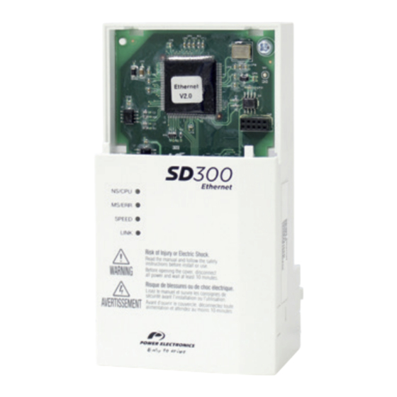
Page 18: Layout Of The Module
SD300 - ETHERNET MODULE POWER ELECTRONICS Layout of the module ETHERNET COMMUNICATION MODULE FEATURES... -
Page 19: Installation And Connection
If the Ethernet communication module is removed or installed, the power supply should be switched off. Otherwise, the SD300 drive may get damaged and warranty will be voided. Take off Ethernet communication module from the product after the power supply is totally discharged. - Page 20 SD300 - ETHERNET MODULE POWER ELECTRONICS Remove the keypad Unfasten the screw from I/O the board and fasten the prepared brass bars. INSTALLATION AND CONNECTION...
- Page 21 POWER ELECTRONICS SD300 - ETHERNET MODULE Mount Ethernet communication module and fasten the two brass bar screws (one was removed in step 4; the second is included in the kit). INSTALLATION AND CONNECTION...
- Page 22 SD300 - ETHERNET MODULE POWER ELECTRONICS Install the keypad and the communication module cover. INSTALLATION AND CONNECTION...
- Page 23 POWER ELECTRONICS SD300 - ETHERNET MODULE Install the front cover again. INSTALLATION AND CONNECTION...
-
Page 24: Terminal Block Of Ethernet Communication
SD300 - ETHERNET MODULE POWER ELECTRONICS Terminal Block of Ethernet Communication Specification Pin No. Signal Description Cable color Transmitting data Plus White / Yellow Transmitting data Minus Yellow Receiving data Plus White / Green None Not used Blue None Not used... -
Page 25: Network Cable Specification
POWER ELECTRONICS SD300 - ETHERNET MODULE Network cable specification Category 5 is used. Transmission speed of category 5 is 100MHz and available up to 100Mbps. Classification Detail Used UTP (U.UTP) Maximum 200MHz, Unshielded twisted Voice + Information (Data) + Low video... -
Page 26: Protocol Selection
SD300 - ETHERNET MODULE POWER ELECTRONICS Protocol Selection The Ethernet communication module supports two communication protocols: Modbus TCP and Ethernet IP. Use switch number 1 (located next to the Ethernet cable connector) at the bottom of the module to select the protocol. Switch number 2, 3 and 4 are not available. -
Page 27: Leds Description
POWER ELECTRONICS SD300 - ETHERNET MODULE LEDs description The Ethernet module has four LEDs that show its status at all times. The behaviour of the first two, from left to right, depends on the active communication protocol (Modbus TCP or Ethernet IP), while the other two (SPEED and LINK) have the same behaviour for both protocols. - Page 28 SD300 - ETHERNET MODULE POWER ELECTRONICS The status of Ethernet Line LED (Ethernet/IP and Modbus/TCP are the same) COLOR STATUS FUNCTION Communication speed is 100Mbps. SPEED Green Communication speed is 10Mbps. Ready to communicate. LINK Green There is a problem with the communication cable. Check if wiring is correct.
- Page 29 POWER ELECTRONICS SD300 - ETHERNET MODULE The status of Ethernet/IP LED & Troubleshooting COLOR STATUS DESCRIPTION The status is I/O communicating when Class 1 connection is well connected. Green Client and TCP are not connected. FLASH UCMM communication is available once client and TCP are connected.
-
Page 30: Modbus Tcp
SD300 - ETHERNET MODULE POWER ELECTRONICS MODBUS TCP Modbus TCP frame structure Modbus TCP frame can be divided in two parts: header + PDU. Modbus Application Protocol (MBAP) Protocol Data unit Header: 7 bytes (PDU): 5 bytes ~ Generally, Ethernet uses Ethernet II Frame. -
Page 31: Function Codes
Please, refer to the Getting Started manual of your SD300 for further information on Modbus functions and examples. Exception Frame If there is any error while the Client sends data to the Server, an exception frame will be sent to the Client. - Page 32 SD300 - ETHERNET MODULE POWER ELECTRONICS Type Code Description Illegal Function 0x01 The required function is not supported. Illegal Data Address 0x02 Unused address is required or to be modified. The modified data exceeds the permitted Illegal Data Value 0x03 range when it needs to modify the data.
-
Page 33: Ethernet Ip
Industrial Protocol), defined by the ODVA, by using TCP and UDP. • Originator: Device requesting connection, called Client. The device represents a PLC or a scanner. • Target: Device that responds to the connection, called Server. The device represents a SD300 drive. ETHERNET IP... -
Page 34: Implicit Messaging
SD300 - ETHERNET MODULE POWER ELECTRONICS Ethernet/IP Layers Implicit Messaging An Implicit Message is also called an I/O Message, which are the data communicated between the Client (Originator) and the Server (Target) at present period by the Input Instance and Output Instance. The connection is in Class 1. -
Page 35: Supported Range
POWER ELECTRONICS SD300 - ETHERNET MODULE Supported range • Transport Type Originator->Target: Point to Point Target->Originator: Multicast • Transport Trigger: Cyclic • Configuration Connection: 1 • Connection Tag: Not supported • Priority Originator->Target: Scheduled Target->Originator: Scheduled Configuration Data: Not supported... -
Page 36: Input Instance
SD300 - ETHERNET MODULE POWER ELECTRONICS Input instance Drive status data periodically sent from the drive to a PLC or Client device. Instance Byte Bit 7 Bit 6 Bit 5 Bit 4 Bit 3 Bit 2 Bit 1 Bit 0... - Page 37 POWER ELECTRONICS SD300 - ETHERNET MODULE Instance Byte Bit 7 Bit 6 Bit 5 Bit 4 Bit 3 Bit 2 Bit 1 Bit 0 Status Parameter - 1 data (Hi Byte) Status Parameter - 2 data (Low Byte) Status Parameter - 2 data (Hi Byte)
- Page 38 SD300 - ETHERNET MODULE POWER ELECTRONICS Instance Byte Bit 7 Bit 6 Bit 5 Bit 4 Bit 3 Bit 2 Bit 1 Bit 0 Status Parameter - 6 data (Hi Byte) Status Parameter - 7 data (Low Byte) Status Parameter - 7 data (Hi Byte)
-
Page 39: Output Instance
POWER ELECTRONICS SD300 - ETHERNET MODULE Output instance Command data sent periodically from the PLC or a Client to the drive. Instance Byte Bit 7 Bit 6 Bit 5 Bit 4 Bit 3 Bit 2 Bit 1 Bit 0 Fault... - Page 40 SD300 - ETHERNET MODULE POWER ELECTRONICS Instance Byte Bit 7 Bit 6 Bit 5 Bit 4 Bit 3 Bit 2 Bit 1 Bit 0 Control Parameter - 3 data (Low Byte) Control Parameter - 3 data (Hi Byte) Control Parameter - 4 data (Low Byte)
- Page 41 POWER ELECTRONICS SD300 - ETHERNET MODULE Instance Byte Bit 7 Bit 6 Bit 5 Bit 4 Bit 3 Bit 2 Bit 1 Bit 0 Control Parameter - 1 data (Low Byte) Control Parameter - 1 data (Hi Byte) Control Parameter - 2 data (Low Byte)
-
Page 42: Explicit Messaging
Product Name 12 Bytes SD300 Ethernet [1] Product code ‘6’ means SD300 AC drive. [2] The Upper and Lower byte represent the Major Revision and Minor Revision, respectively. For example, 0x0102 means 2.01. The version of the Ethernet communication is indicated in CM.6. - Page 43 POWER ELECTRONICS SD300 - ETHERNET MODULE Status bits (definition of each bit of status): Definition 0: Device is not connected to Master. 1: Device is connected to Master. Reserved Configured (always ‘0’ since Ethernet/IP is not supported.) Reserved 0: Unknown 2: in case of incorrect I/O connection.
-
Page 44: Motor Data Object (Class 0X28, Instance 1)
SD300 - ETHERNET MODULE POWER ELECTRONICS Motor data object (Class 0x28, Instance 1) Attributes: Attribute Attribute ID Access Range Definition Name 0: Non-standard motor 1: PM DC Motor 2: FC DC Motor 3: PM Synchronous Motor 4: FC Synchronous Motor... -
Page 45: Control Supervisor Object (Class 0X29, Instance 1)
POWER ELECTRONICS SD300 - ETHERNET MODULE Control supervisor object (Class 0x29, Instance Attributes: Attribute Attribute ID Access Range Definition Name Stop Forward Operation in normal direction. See Get / Set Run Cmd. “Drive Run Command” description below this table. Stop Reverse Operation in reverse direction. - Page 46 SD300 - ETHERNET MODULE POWER ELECTRONICS Attribute Attribute ID Access Range Definition Name Code Provide operation reference through a source other than Control FieldBus communication. From Net. Provide operation reference through FieldBus communication source. Drive Run Command: It is the drive operation using Forward Run Cmd.
- Page 47 POWER ELECTRONICS SD300 - ETHERNET MODULE Fault Code Number Description 0x0000 None Ethermal Out Phase Open InverterOLT InPhaseOpen Thermal Trip UnderLoad ParaWriteTrip IOBoardTrip PrePIDFail OptionTrip1 OptionTrip2 OptionTrip3 0x1000 LostCommand UNDEFINED LostKeypad 0x2200 OverLoad 0x2310 OverCurrent1 0x2330 0x2340 OverCurrent2 0x3210 OverVoltage...
-
Page 48: Ac Drive Object (Class 0X2A; Instance 1)
SD300 - ETHERNET MODULE POWER ELECTRONICS AC Drive Object (Class 0x2A; Instance 1) Attributes: Attribute Attribute ID Access Range Definition Name The output frequency has not reached the set up frequency, yet. Reference The output frequency has reached the set up frequency. - Page 49 POWER ELECTRONICS SD300 - ETHERNET MODULE Attribute Attribute ID Access Range Definition Name Deceleration 0-6000.0 Set-up/monitor Inverter Get/Set Time deceleration time. Service: Service Code Definition Support for Class Support for Instance Attribute 0x0E Single Attribute 0x10 Single [3] dr-04: Dec Time value.
-
Page 50: Class 0X64 (Drive Object) - Manufacture Profile
SD300 - ETHERNET MODULE POWER ELECTRONICS Class 0x64 (Drive Object) – Manufacture Profile This is the object to access Keypad Parameters of the Inverter. Attributes: Attribute Attribute ID Access Range Definition Name 1 (dr Group) 2 (bA Group) 3 (Ad Group) -
Page 51: Parameters Configuration
Drive parameters related to Modbus/TCP and Ethernet/IP communication are listed below. Protocol ‘M’ is used for Modbus/TCP and Protocol ‘E’ is used for Ethernet/IP. Note: For further information about SD300 programming parameters, please refer to the Getting Started Manual. Default... - Page 52 SD300 - ETHERNET MODULE POWER ELECTRONICS Default Screen Description Range Function Protocol value ETHERNET IP: It represents the ON/OFF status of the 2 LEDs on the right side among the 4 LEDs on the keypad parameter CM.9. 4 bits can be displayed in CM.9 by using keypad.
- Page 53 POWER ELECTRONICS SD300 - ETHERNET MODULE Default Screen Description Range Function Protocol value Note: Comes from the previous page. Example 2: CM.9 LED in Ethernet IP operation LED STATE MS (Red) NS (Red) (Green) (Green) The IP version supported by Ethernet 0 to CM.10...
- Page 54 SD300 - ETHERNET MODULE POWER ELECTRONICS Default Screen Description Range Function Protocol value Note: Comes from the previous page. 0 to CM.19 Parameter10 Code Name of Input 0 to number parameter value CM.20 Parameter11 CM.10 Parameter1 CM.11 Parameter 2 CM.12 Parameter 3 CM.13...
- Page 55 POWER ELECTRONICS SD300 - ETHERNET MODULE Default Screen Description Range Function Protocol value This parameter is displayed when the protocol is set to Ethernet/IP. It sets up the data format of the drive status sent from the drive to the Client (Originator) during the I/O communication module of the CIP (Common Industrial Protocol).
- Page 56 SD300 - ETHERNET MODULE POWER ELECTRONICS Default Screen Description Range Function Protocol value CM.35 The size of the group is set in CM.30. 0x0000 CM.36 0x0000 CM.37 0x0000 CM.38 0x0000 This parameter is displayed only when the protocol is set to Ethernet IP. It sets up the...
- Page 57 POWER ELECTRONICS SD300 - ETHERNET MODULE Default Screen Description Range Function Protocol value CM.51 0x0005 CM.52 0x0006 These parameters are not used in Modbus CM.53 0x0000 TCP. CM.54 0x000 Define the input parameter group for data 0x0000 Control 0 to...
-
Page 58: Lost Command
SD300 - ETHERNET MODULE POWER ELECTRONICS LOST COMMAND Drive Keypad Parameters Code Name / Default Set Value Function Number Description Set the action to be taken if the None drive loses a speed reference. See Free-Run RIRLs / “Lost Command Mode” below. -
Page 59: Modbus/Tcp Lost Command Status
POWER ELECTRONICS SD300 - ETHERNET MODULE Modbus/TCP Lost Command Status If the Modbus TCP receives no data from Client for 100msec, the Option becomes Lost Command status, and after the time set up in the Pr-13, the Drive operates according to the settings in the Pr-12. -
Page 60: Configuration Register
SD300 - ETHERNET MODULE POWER ELECTRONICS CONFIGURATION REGISTER VARIABLE SPEED DRIVE: SD300. SERIAL Nº: MODEL: APPLICATION: DATE: CUSTOMER: NOTES: PARAMETER / DEFAULT SETTING 1 SETTING 2 DESCRIPTION VALUE CM: Communication Bus CM.6 0.00 __________________ __________________ Communication S/W version CM.9 __________________... - Page 61 POWER ELECTRONICS SD300 - ETHERNET MODULE PARAMETER / DEFAULT SETTING 1 SETTING 2 DESCRIPTION VALUE CM.19 __________________ __________________ Opt Parameter10 CM.20 __________________ __________________ Opt Parameter11 CM.21 __________________ __________________ Opt Parameter12 CM.22 __________________ __________________ Opt Parameter13 CM.29 __________________ __________________ CIP Input Instance CM.30...
- Page 62 SD300 - ETHERNET MODULE POWER ELECTRONICS PARAMETER / DEFAULT SETTING 1 SETTING 2 DESCRIPTION VALUE CM.55 0x0000 __________________ __________________ Control parameter 5 CM.56 0x0000 __________________ __________________ Control parameter 6 CM.57 0x0000 __________________ __________________ Control parameter 7 CM.58 0x0000 __________________ __________________ Control parameter 8 CM.94...
- Page 63 24h Technical Assistance 365 days a year Find your nearest delegation: http://power-electronics.com/contact/ Follow us on:...
Need help?
Do you have a question about the SD300 and is the answer not in the manual?
Questions and answers