Advertisement
Quick Links
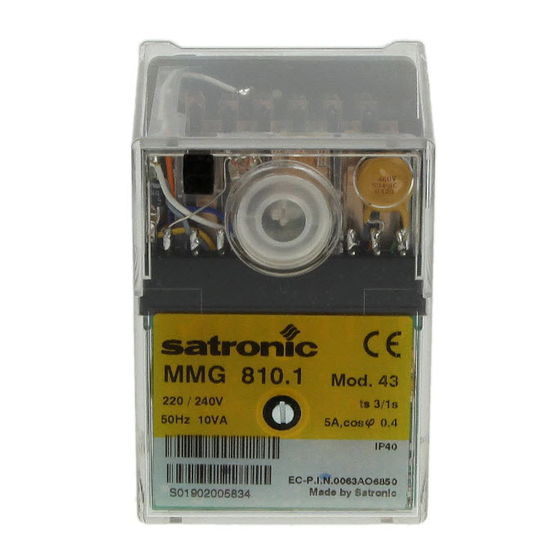
Burner Control Box
For 2-stage forced draught and combi oil/gas
burners
Suitable flame detectors:
- Ionisation probe
- UV sensor
- Infra-red flicker detector
INTRODUCTION
The MMG burner control box is capable of controlling
and monitoring forced draught and combi oil/gas burners
of any nominal rating (tested and approved as per EN 298).
The MMG 810.1 model 33 control boxes are also suitable for
use in stationary warm air generators (Direct air heaters
according to DIN 4794).
Different type and model designations identify the control
boxes according to varying national standards, and to some
extent, according to programme times.
TYPES AVAILABLE
MMG 810.1 Mod. 32
Mod. 33
Mod. 43
Mod. 45
MMG 811.1 Mod. 33
Mod. 63
ONSTRUCTIONAL FEATURES
The control box is enclosed in a protective, flame resistant,
transparent, plug-in type plastic housing, and includes:
– Synchronous motor with reduction gearing driving cam
switch
– Cam switch with informative, coloured programme in-
dicator
– 12-way cam switch assembly controlling the programme
sequence
– Electronic components on plug-in printed circuit
The following important indicators and operating controls
are situated on the front of the control box:
– Reset button incorporating signal lamp for malfunction
(lockout)
– Coloured programme indicator
– Central screw fastening
Art. Nr. 0640120
Art. Nr. 0640220
Art. Nr. 0642520
Art. Nr. 0642620
Art. Nr. 0640520
Art. Nr. 0640420
MMG 810.1 / 811.1
A Honeywell Company
TECHNICAL DATA
Supply voltage
AC frequency variations
Fuse rating
Power consumption
Max. current per output
term. 3
term. 4, B
term. 5, 6, C
Total load
Amplifier sensitivity
Min. current from UV tube
or ionisation probe
Flame detector cable
Air proving switch
Reset delay
Flame detector
- Ionisation probe
- Infra-red flicker detector
- UV tube type
Infra red flare detector
Weight incl. base
Mounting attitude
Insulation standard
Permissable ambient temp.
Classified acc. to EN 298
program timings (sec.)
Model
Waiting time
at start-up
tw
Max. reaction
time for air
proving switch
tlw
Pre-purge time
tv1
Pre-ignition time tvz
T. ignition time
tz
Safety time
ts
Time delay
term.6 / term.C
tv2
For external resetting, the remote reset device FR 870
(art. No. 70700) can be utilized. (Refer to doc. 750).
1
220 / 240 V (-15... +10%)
50 Hz (50 - 60 Hz)
result in proportional timing
deviations
max. 10 A rapid, 6 A slow
10 VA
2A, cos ϕ 0.2
2A, cos ϕ 0.4
1A, cos ϕ 0.4
5A, cos ϕ 0.4
1 µA
5 µA
max. 20 m cable length
1 terminal 4 A, 230 V
none
IRD 1020.1 end-on
UVZ 780 red markings
installed radially or axially
IRD 1020
350 g
any
IP 44
-20° C... +60° C
BTLLXN
MMG 810.1
811.1
32
33
43
45
33
9
9
9
9
9
6
6
6
6
6
24
24
40
40
24
3
3
3
3
3
6
6
6
8
6
2
3
3
5
3
10
10
10
10
10
63
6
5
55
3
5.5
3
6
Advertisement

Related Manuals for Satronic MMG 810.1

Summary of Contents for Satronic MMG 810.1
- Page 1 (tested and approved as per EN 298). The MMG 810.1 model 33 control boxes are also suitable for use in stationary warm air generators (Direct air heaters according to DIN 4794).
- Page 2 4 A / 220 V are sufficient. b) Close the manual valve in operating position with the gas – On the MMG 810.1, switch contacts (e.g. valve end monitor contact bridged. contact) can be wired between terminals 1 and 9. These –...
- Page 3 SCHEMATIC CONNECTION DIAGRAM AND PROCESS DIAGRAM MMG 810.1 max. 10 A rapid 6 A slow for ign. spark detection only Mains switch Gas pressure switch Limit thermostat Control thermostat Ionisation probe UV sensor tw tlw tv1 tvz tz ts tv2...
- Page 4 5 µA. 15.1 0-100 µA 0-10 µA ø20.5 ORDERING INFORMATION ITEM DESIGNATION ITEM NO. Control box Type MMG 810.1 mod. 33 0640220 Type MMG 811.1 mod. 33 0640520 Socket Wiring base S98 12-pin 75310 Slide-in plate Cable terminal plate 70502...
Need help?
Do you have a question about the MMG 810.1 and is the answer not in the manual?
Questions and answers