Table of Contents
Advertisement
Quick Links
certified Qualitysystem
ISO 9001 / EN 29001
Reg. Nr. 10529
Gas burner automatic
safety control
For 2-stage forced draught and combi oil/
gas burners
Possible flame detectors:
- Ionization probe
- Infrared flicker detector
INTRODUCTION
The gas burner automatic safety control MMI controls
and monitors blown gas- and combined burners of any
nominal thermal load (tested and certified according to
EN 298).
The automatic safety controls MMI 810.1 models 13, 33 and
35 can also be utilized for burners on fixed hot air heaters
(Direct air heaters according to DIN 4794).
Various types and model designations differentiate the
automatic safety controls with respect to the programme
times, as well as with regard to differing national standards.
TYPES AVAILABLE
MMI 810.1
Mod. 13 *
Mod. 33
Mod. 35
Mod. 43
Mod. 55
MMI 811.1
Mod. 35
Mod. 63
* Must only be used on boilers or other applications where
the 10 second pre-purge time is sufficient to provide at
least 3 volume changes of the combustion chamber.
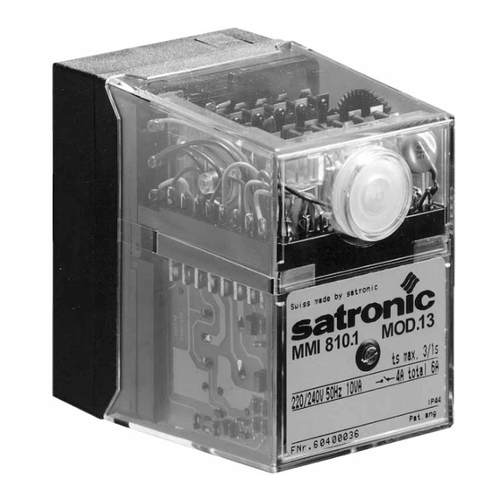
CONSTRUCTIONAL FEATURES
The automatic control is housed in a non-inflammable,
transparent, plug-in type plastic case and contains:
–
Synchronous motor with speed reducer gears as the
drive for the switching cam
–
Switching cam with informative programme display in
colour
–
12 times cam drive for controlling the programme
sequence
–
Plug-in type circuit boards with the electronic components
The following important indicating - and operating elements
are located on the front panel of the automatic control:
– Illuminated pushbutton for indication of malfunctions
and reset
– Programme display in colour
– Screw for central mounting
Art. Nr. 0620720
Art. Nr. 0620220
Art. Nr. 0620920
Art. Nr. 0622520
Art. Nr. 0621320
Art. Nr. 0621120
Art. Nr. 0620420
MMI 810.1 / 811.1
A Honeywell Company
TECHNICAL DATA
Operating voltage
Differing frequency
Rating fuse
Power consumption
Max. load per output:
- term. 3
- term. 4, B
- term. 5, 6
total load
Amplifier sensitivity
Minimum required
Ionization current
Flame detector cable
Air pressure monitor
Waiting time for
malfunction remedy
Flame detector
- Ionization probe
- Infrared flicker detector
Weight, incl. base
Mounting position
Insulation standard
Admissible ambient
temperature for controller
and flame detector
Classified acc. to EN 298
program
timings (sec.)
Modell
13
Waiting time
at start ca.
tw
6
Max. reaction
time for air
proving switch tlw 3.5
Pre-purge time tv1
3
Pre-ignition
time
tvz
2
T. ignition time
tz
5
Safety time
ts
3
Time delay
term.6/term.C tv2
6
For external resetting, the remote reset device FR 870
(art. No. 70700) can be utilized. (Refer to doc. 750).
1
220 / 240 V (-15... +10%)
50 Hz (50 - 60 Hz)
Results in a proportional
deviation of the time.
max. 10 A rapid, 6 A slow
10 VA
2A, cos ϕ 0.2
2A, cos ϕ 0.4
1A, cos ϕ 0.4
5A, cos ϕ 0.4
1 µA
5 µA
max. 20 m cable length
working contact 4 A, 230 V
None
IRD 1020
350 g
any
IP 44
-20° C... +60° C
BTLLXN
MMI 810.1
811.1
33
35
43
55
35
63
9
9
9
9
9
6
6
6
17
6
24
24
40
20
24
55
3
3
3
15
3
6
8
6
20
8
5.5
3
5
3
5
5
10
10
10
10
10
6
5
3
3
6
Advertisement
Table of Contents

Related Manuals for Satronic 0620720

Summary of Contents for Satronic 0620720
- Page 1 TYPES AVAILABLE - term. 3 2A, cos ϕ 0.4 - term. 4, B MMI 810.1 Mod. 13 * Art. Nr. 0620720 1A, cos ϕ 0.4 - term. 5, 6 Mod. 33 Art. Nr. 0620220 5A, cos ϕ 0.4 total load 1 µA...
- Page 2 APPLICATION TECHNOLOGY FEATURES COMMISSIONING AND SERVICE/MAINTENANCE 1. Flame Monitoring 1. Important Remarks The flame monitoring can be effected with the following – Before commissioning, the wiring has to be accurately flame detectors: checked. Faulty wiring can damage the unit and endanger - With ionization electrodes in power grids with earthed the safety of the installation.
- Page 3 SCHEMATIC CONNECTION DIAGRAM AND PROCESS DIAGRAM MMI 810.1 max. 10 A rapid 6 A slow Main switch Gas pressure switch Limit thermostat Control thermostat Ionization probe tw tlw tv1 tvz tz ts tv2 Ignition Burner motor Solenoid valve 1st stage SCHEMATIC CONNECTION DIAGRAM AND PROCESS DIAGRAM MMI 811.1 Solenoid valve 2nd stage Air pressure monitor...
- Page 4 PG 11 The signal should be greater than 5 µA 0 - 10 µA 0 - 100 µA Slide-in plate Reset button The Satronic Ionimeter is ideal for making this measurement. Earth ø 16 mm, 57-60 cable entry from below...
Need help?
Do you have a question about the 0620720 and is the answer not in the manual?
Questions and answers