Advertisement
Quick Links
heck
C
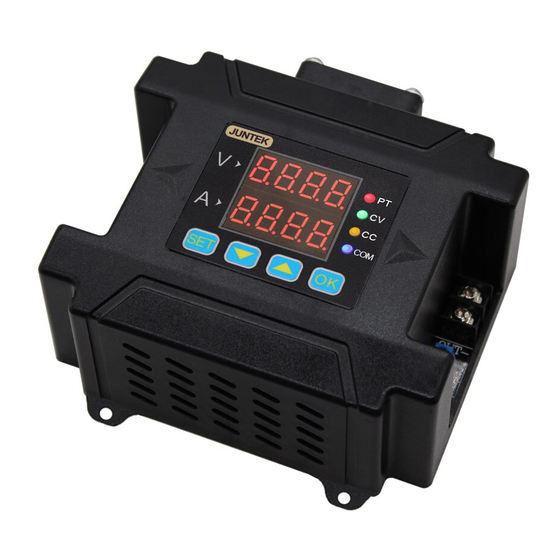
When you get a new DPM8600 series programmable high power power
supply, it is recommended that you check the instrument as follows.
1. Check for damage caused by shipping.
If the packaging carton or bubble bag protection pad is found to be
severely damaged, please keep it until the whole machine and accessories
pass the test.
2. Check that the contents of the box are complete.
The contents of the box are as follows. If the content does not match or
the instrument is damaged, please contact your dealer or the company.
Host: DPM8600 programmable high power power supply *1
Accessories:
Optional:Programmable power wireless remote control
5V USB transfer cable
User Manual
Check the whole machine.
3.
If the instrument is found to be damaged, the instrument is not working
properly, or fails the performance test, please contact your dealer or the
company.
1
User Manual
1
*1
*1
*1
*1
Advertisement

Subscribe to Our Youtube Channel
Related Manuals for Juntek DPM8600 Series

Summary of Contents for Juntek DPM8600 Series
- Page 1 When you get a new DPM8600 series programmable high power power supply, it is recommended that you check the instrument as follows. 1. Check for damage caused by shipping. If the packaging carton or bubble bag protection pad is found to be severely damaged, please keep it until the whole machine and accessories pass the test.
- Page 2 The DPM8600 series power supplies are single output programmable high power switching power supplies, large output power, small size, beautifully structured. At the same time, it is equipped with TTL serial communication interface and RS485 communication interface, which provides serial communication protocol, it can also be applied to modbus-...
- Page 3 【 】 Switching power supply instructions The following description uses the DPM8624 as an example. The DPM8608 operates in the same way as the DPM8624. The difference is in the current display. The DPM8608 and DPM8605 currents display three decimal places such as: 3.000, and the DPM8624 and DPM8616 currents display two decimal places such as 03.00.
- Page 4 Figure 2-1 DPM8600 series digital power supply module description (DPM8616/DPM8624) Label Description Label Description Working status Power Switch ① ⑥ indicator Negative Input Positive Output ② ⑦ Positive Input Negative Output ③ ⑧ Communication LED digital tube ④ ⑨ Interface Function button ⑤...
- Page 5 Table 2-2 Display description of DPM8600 series power supply...
- Page 6 PT: Overheat protection indicator, when the temperature is greater than 80 °C, the PT light is on to indicate overheat protection. CV: Constant voltage indicator, CV indicator light indicates constant voltage output. CC: Constant current indicator, CC indicator light indicates constant current output. COM: Communication indicator, when there is an instruction input, the COM light will be on, indicating communicating.
- Page 7 follows (blue indicates digital flashing): Short press The default setting Short press many times,the is 5V, 3A. certain value flashes. flashing bit will move different bits voltage and current. load Press to turn The value current reaches the set the output on and off, be change the value current, the output is as the load current is...
- Page 8 Press Press switch to the below switch to the below interface. interface. Press Press to load Press to load settings of M9.or to adjust to M3, settings of M0.or press OK to load press to enter press to enter settings of M3. next interface.
- Page 9 Corr calibration function introduction 1.When the set voltage is greater than 20V, for example, 25V is set as the output voltage, but the load is not connected, the display voltage of 25V and the current of zero point (that is, the current is calibrated to zero) are calibrated.
- Page 10 Default interface. Long press Short press enter the voltage and enter the factory reset current upper and lower interface, press limit save interface, change to change the sub-option by pressing the sub-option, N , 10 means the means "no", Y means current voltage and current "yes", then press OK, value is set to the upper...
- Page 11 Introduction of voltage and current upper and lower limits: The upper and lower limits of the voltage and current are set voltage upper limit adjustment limits and lower limit adjustment limits. For example: set 30V, 5A in the main interface, enter the voltage and current upper limit save position, press OK to save it as the upper limit of voltage and current, and the product's voltage adjustment range is up to 30V, the maximum current is 5A.
- Page 12 【 】 Wireless controller instructions The wireless controller uses a 2.4G frequency RF module to transmit signals wirelessly with the power supply, up to 10 meters remote control. The wireless controller has a built-in 3.7V, 2000mA lithium battery that can be recharged.
-
Page 14: Operating Instructions
1 Product model 2 Signal indication 3 Key lock 4 Address 01-99 5 Channel 01-30 6 Battery Capacity 7 Output voltage 8 Output current 9 Output power 10 Voltage setting 11 Current setting 12 Temperature display 13 Capacity 14 Running time 15 Operating status 16 Function bar 17 Constant current indicator... - Page 15 Boot default Voltage setting state Current setting connection status state The output status interface is as follows: When constant When the load current voltage output is 5V, reaches load current, the output is current is less than the the set current, the set current, the output constant current...
- Page 16 Press the SET button Press the OK button to enter the function and the cursor will adjustment and change appear in the function the parameters with the left and right buttons or box position. knob. 三、 Quickly load: Press M1, M2, M3, M4 to quickly load the data in M1, M2, M3, M4 storage locations.
- Page 17 Upper and lower limit display interface: When the adjustment voltage The upper limit value is the same as the lower limit value and current reach the upper and it is displayed as LOCK. limit, it is displayed as MAX. Number Items eatures Load...
- Page 18 Number Items eatures Upper limit Set a parameter in the set voltage and current box to setting enter the upper limit setting function. Press OK to indicate that the setting is successful. After the setting is successful, when the upper limit is adjusted, the setting area will display MAX, indicating that the upper limit has been reached.
Need help?
Do you have a question about the DPM8600 Series and is the answer not in the manual?
Questions and answers